EP0855245A1 - Machine outil avec appareil de rinçage - Google Patents
Machine outil avec appareil de rinçage Download PDFInfo
- Publication number
- EP0855245A1 EP0855245A1 EP97119028A EP97119028A EP0855245A1 EP 0855245 A1 EP0855245 A1 EP 0855245A1 EP 97119028 A EP97119028 A EP 97119028A EP 97119028 A EP97119028 A EP 97119028A EP 0855245 A1 EP0855245 A1 EP 0855245A1
- Authority
- EP
- European Patent Office
- Prior art keywords
- tool
- machine tool
- coolant
- spray nozzles
- tool holder
- Prior art date
- Legal status (The legal status is an assumption and is not a legal conclusion. Google has not performed a legal analysis and makes no representation as to the accuracy of the status listed.)
- Ceased
Links
Images

Classifications
-
- B—PERFORMING OPERATIONS; TRANSPORTING
- B23—MACHINE TOOLS; METAL-WORKING NOT OTHERWISE PROVIDED FOR
- B23Q—DETAILS, COMPONENTS, OR ACCESSORIES FOR MACHINE TOOLS, e.g. ARRANGEMENTS FOR COPYING OR CONTROLLING; MACHINE TOOLS IN GENERAL CHARACTERISED BY THE CONSTRUCTION OF PARTICULAR DETAILS OR COMPONENTS; COMBINATIONS OR ASSOCIATIONS OF METAL-WORKING MACHINES, NOT DIRECTED TO A PARTICULAR RESULT
- B23Q13/00—Equipment for use with tools or cutters when not in operation, e.g. protectors for storage
-
- B—PERFORMING OPERATIONS; TRANSPORTING
- B23—MACHINE TOOLS; METAL-WORKING NOT OTHERWISE PROVIDED FOR
- B23Q—DETAILS, COMPONENTS, OR ACCESSORIES FOR MACHINE TOOLS, e.g. ARRANGEMENTS FOR COPYING OR CONTROLLING; MACHINE TOOLS IN GENERAL CHARACTERISED BY THE CONSTRUCTION OF PARTICULAR DETAILS OR COMPONENTS; COMBINATIONS OR ASSOCIATIONS OF METAL-WORKING MACHINES, NOT DIRECTED TO A PARTICULAR RESULT
- B23Q11/00—Accessories fitted to machine tools for keeping tools or parts of the machine in good working condition or for cooling work; Safety devices specially combined with or arranged in, or specially adapted for use in connection with, machine tools
- B23Q11/0042—Devices for removing chips
- B23Q11/005—Devices for removing chips by blowing
-
- B—PERFORMING OPERATIONS; TRANSPORTING
- B23—MACHINE TOOLS; METAL-WORKING NOT OTHERWISE PROVIDED FOR
- B23Q—DETAILS, COMPONENTS, OR ACCESSORIES FOR MACHINE TOOLS, e.g. ARRANGEMENTS FOR COPYING OR CONTROLLING; MACHINE TOOLS IN GENERAL CHARACTERISED BY THE CONSTRUCTION OF PARTICULAR DETAILS OR COMPONENTS; COMBINATIONS OR ASSOCIATIONS OF METAL-WORKING MACHINES, NOT DIRECTED TO A PARTICULAR RESULT
- B23Q11/00—Accessories fitted to machine tools for keeping tools or parts of the machine in good working condition or for cooling work; Safety devices specially combined with or arranged in, or specially adapted for use in connection with, machine tools
- B23Q11/10—Arrangements for cooling or lubricating tools or work
-
- B—PERFORMING OPERATIONS; TRANSPORTING
- B23—MACHINE TOOLS; METAL-WORKING NOT OTHERWISE PROVIDED FOR
- B23Q—DETAILS, COMPONENTS, OR ACCESSORIES FOR MACHINE TOOLS, e.g. ARRANGEMENTS FOR COPYING OR CONTROLLING; MACHINE TOOLS IN GENERAL CHARACTERISED BY THE CONSTRUCTION OF PARTICULAR DETAILS OR COMPONENTS; COMBINATIONS OR ASSOCIATIONS OF METAL-WORKING MACHINES, NOT DIRECTED TO A PARTICULAR RESULT
- B23Q3/00—Devices holding, supporting, or positioning work or tools, of a kind normally removable from the machine
- B23Q3/155—Arrangements for automatic insertion or removal of tools, e.g. combined with manual handling
- B23Q3/1552—Arrangements for automatic insertion or removal of tools, e.g. combined with manual handling parts of devices for automatically inserting or removing tools
- B23Q3/15526—Storage devices; Drive mechanisms therefor
- B23Q3/15534—Magazines mounted on the spindle
-
- B—PERFORMING OPERATIONS; TRANSPORTING
- B23—MACHINE TOOLS; METAL-WORKING NOT OTHERWISE PROVIDED FOR
- B23Q—DETAILS, COMPONENTS, OR ACCESSORIES FOR MACHINE TOOLS, e.g. ARRANGEMENTS FOR COPYING OR CONTROLLING; MACHINE TOOLS IN GENERAL CHARACTERISED BY THE CONSTRUCTION OF PARTICULAR DETAILS OR COMPONENTS; COMBINATIONS OR ASSOCIATIONS OF METAL-WORKING MACHINES, NOT DIRECTED TO A PARTICULAR RESULT
- B23Q3/00—Devices holding, supporting, or positioning work or tools, of a kind normally removable from the machine
- B23Q3/155—Arrangements for automatic insertion or removal of tools, e.g. combined with manual handling
- B23Q3/157—Arrangements for automatic insertion or removal of tools, e.g. combined with manual handling of rotary tools
- B23Q3/15706—Arrangements for automatic insertion or removal of tools, e.g. combined with manual handling of rotary tools a single tool being inserted in a spindle directly from a storage device, i.e. without using transfer devices
Definitions
- the present invention relates to a machine tool a spindle and a tool changing device with several Tool changers for transferring tool holders between their respective magazine position and a working position the spindle.
- a machine tool of the type mentioned above is from the DE 40 31 997 A1 known.
- the known machine tool has one in a headstock rotatably mounted spindle, centric on the front side a holder for tool holders is provided.
- Such tool holders are usually standardized, they have a steep cone, which is complementary to the inclusion in the Spindle is.
- the steep cone closes down thickened collar on which a gripper groove is provided.
- a holding shaft extends below the covenant Tools can be attached.
- Steep cones of this type can also be designed as hollow cone shafts be provided with an upper opening through the pliers segments and the tension cone of a clamping system in the Intervene inside the tapered hollow shaft to insert it into the Move in recording.
- the face contact between the spindle and Tool holder is not primarily done here via the conical Outer surface of the hollow cone shaft but over an upward pointing ring surface of the thickened covenant, the front the spindle comes into face contact when the tool holder is in the recording is withdrawn.
- a sleeve surrounding the spindle provided that move relative to the longitudinal axis of the spindle can be.
- a tool changing device on the sleeve arranged, which comprises a number of tool changers, of each of which carries a tool holder as described above.
- Each tool changer is equipped with a gripper hand which grips the tool changer on the gripper groove.
- the gripper hand is in turn supported on two gripper arms, that form a parallelogram guide.
- One of the gripper arms is with a drive unit consisting of cylinder and piston rod connected, by extending and retracting the piston rod the gripper hand and thus the tool holder carried by it from the magazine position to the working position on the spindle or from the working position back to the magazine position is transferred.
- the tool holders with their are in the magazine position Steep cones or hollow taper shanks are inserted into quivers protect the tool holder from dirt.
- this object is achieved in the aforementioned Machine tool solved in that a flushing device for Rinsing the machine tool in the area of the tool changing device is provided with coolant.
- the inventors of the present application have recognized that that surprisingly the interfering chips not only during the processing of a workpiece but in particular also while replacing a tool holder on it Tool holder. It has been found that with Chips contaminated coolant during the tool change process, so while both the one to be changed as well the tool holder to be replaced is free and unprotected by the working area of the machine tool can be moved from the Tool changing device drips itself and thereby on the Tool holder arrives.
- the flushing device preferably only during a workpiece machining the tool changing device rinsed with coolant.
- the flushing device uses spray nozzles includes the above the magazine position of the tool holder are arranged.
- the spray nozzles are arranged so far up be that also in the area of the magazine position parts of the tool changing device are also cleaned will.
- the spray nozzles ensure good distribution of the coolant and on the other hand limit the coolant consumption, that when using gush feed Coolant would be significantly larger.
- Spray nozzles coolant during the machining of the workpiece fed to the tool changer in the magazine position remove any chips from the existing tool holder, by machining the workpiece in the work area of the Flying machine tool.
- the spray cone is sufficient the spray nozzles but also so far that the tool changer of the tool holder in use is also cleaned. It should also be noted that usually 8, 12, 16 or up to 20 tool changers evenly distributed around the spindle are arranged, the tool changer when using the Tool holder remain on this.
- the flushing device Includes spray nozzles that are connected to one another via a ring line are connected, the ring line preferably in itself is closed and a feed pipe as a coolant connection having.
- each spray nozzle is between two adjacent tool changers is arranged, preferably A common spray nozzle is provided for two tool changers is.
- each tool changer has one fluid-operated drive unit with piston rod and cylinder has, the piston rod at one end with a Gripper arm is connected, and the spray nozzles above the Gripper arms are arranged.
- the spray nozzles are namely arranged where also with existing machine tools enough space to attach the flushing device is available.
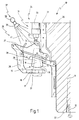
- Fig. 1 10 denotes a machine tool, the one Has spindle 11 with a receptacle 12 for tool holder. Such a tool holder 13 is in Fig. 1 in its Magazine position 15 shown.
- the tool holder 13 has a hollow taper shank 16 which is complementary to the receptacle 12. At the bottom of the Tapered hollow shaft 16 is followed by a thickened collar 17, on which a gripper groove 18 is provided. Furthermore, the federal government 17 an upwardly facing annular surface 19 and one of the Ring surface 19 remote holding shaft 21 for receiving a Tool on. The tool holder comes with its annular surface 19 13 in contact with an end face 22 of the spindle 11, whereby a centered seat with a face contact is provided.
- the machine tool 10 also has a tool changing device 22, which comprises a number of tool changers 25, which are arranged evenly distributed around the spindle 11.
- Each tool changer 25 comprises a gripper hand 26 which Tool holder 13 on the gripper groove 18 holds.
- the gripper hand 26 is attached to two gripper arms 27, 28 which are in themselves known form a parallelogram.
- a quiver 29 is also provided in the the tool holder 13 in its magazine position 15 at least protrudes with its hollow cone 16, whereby the hollow cone shaft is protected from flying chips.
- a drive unit 31 is located above the gripper arms 27, 28 provided a piston rod in a known manner 32 and a cylinder 33 includes.
- the piston rod 32 is with attached its lower end 34 to the gripper arm 27.
- the two gripper arms 27, 28 and each tool changer 25 are attached to a sleeve 35 surrounding the spindle 11, which is displaceable along an arrow indicated at 36.
- a flushing device 37 is provided, which is a ring line 38 comprises, to which at least one spray nozzle 39 is attached.
- This spray nozzle 39 emits a spray cone 41 of coolant, through which the entire tool changing device so during the machining of a workpiece is rinsed, the chips that get into the area of the tool changing device 24 immediately be rinsed off again.
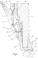
- the piston rod 32 is extended, whereby the Gripper hand 26 pivoted under the spindle 11, as shown in Fig. 2 is shown.
- the sleeve 35 moves in the direction of Arrow 36 down and moves after successful Transfer the tool holder 13 from its magazine position 2 to the working position 53 shown in FIG. whereby the tapered hollow shaft 16 enters the receptacle 12.
- Fig. 2 is a snapshot of this startup of the sleeve 35 shown along arrow 36, where the annular surface 19 still has not come into contact with the end face 22, this does not take place until the sleeve 35 moves further upwards has been.
- the gripper hand 26 remains during processing on the tool holder 13.
- Fig. 2 it can also be seen that the quiver 29 is now through a cover 42 which is arranged on the gripper arm 27, is protected.
- the spray cone 41 of the spray nozzle 39 now sweeps over the entire tool changer 25, so that flying chips themselves cannot start on the tool changer 25.
- FIG. 3 is a plan view of the new machine tool schematically 10, around whose spindle housing 43 the Ring line 38 runs.
- the machine tool 10 comprises a total eight tool changers 25, each between two neighboring ones Tool changer 25, a spray nozzle 39 is provided.
- a supply nozzle 44 for supplying coolant shown. Through this supply nozzle 44 coolant is in the Ring line 38 pressed, which then through the individual spray nozzles 39 is sprayed onto the tool changer 25.
- Fig. 3 it can also be seen that the spray nozzles 39 each are arranged between two flanges 46, 47, wherein between Flanges adjacent spray nozzles 39 a bent piece of pipe 48 runs.
- the entire flushing device 37 comprises eight bent pipe pieces 48 and eight spray nozzles 39, each over the flanges 46, 47 with the adjacent ones Pipe pieces 48 are connected.
- a spray cone is shown again at 41, which here both the tool changer 25a and the tool changer 25b can rinse, so that no second spray nozzle 39 is used could be.
Landscapes
- Engineering & Computer Science (AREA)
- Mechanical Engineering (AREA)
- Auxiliary Devices For Machine Tools (AREA)
Applications Claiming Priority (2)
| Application Number | Priority Date | Filing Date | Title |
|---|---|---|---|
| DE19702974A DE19702974A1 (de) | 1997-01-28 | 1997-01-28 | Werkzeugmaschine mit einer Spülvorrichtung |
| DE19702974 | 1997-01-28 |
Publications (1)
| Publication Number | Publication Date |
|---|---|
| EP0855245A1 true EP0855245A1 (fr) | 1998-07-29 |
Family
ID=7818538
Family Applications (1)
| Application Number | Title | Priority Date | Filing Date |
|---|---|---|---|
| EP97119028A Ceased EP0855245A1 (fr) | 1997-01-28 | 1997-10-31 | Machine outil avec appareil de rinçage |
Country Status (2)
| Country | Link |
|---|---|
| EP (1) | EP0855245A1 (fr) |
| DE (1) | DE19702974A1 (fr) |
Cited By (13)
| Publication number | Priority date | Publication date | Assignee | Title |
|---|---|---|---|---|
| US6409641B1 (en) * | 1998-08-10 | 2002-06-25 | Brother Kogyo Kabushiki Kaisha | Cleaning device for machine tool |
| EP1454709A1 (fr) * | 2003-03-06 | 2004-09-08 | Fanuc Ltd | Dispositif de changement d'outil qui empêche des morceaux adhérant à l'outil |
| EP1495835A1 (fr) * | 2003-07-07 | 2005-01-12 | Fanuc Ltd | Changeur d'outils automatique pour machine-outil, avec dispositif de lavage de la broche porte-outil |
| EP1504845A1 (fr) * | 2003-08-06 | 2005-02-09 | Fanuc Ltd | Dispositif de changement d'outil et méthode de lavage d'outil pour tourelles ou magasins à outils |
| CN101972946A (zh) * | 2010-10-27 | 2011-02-16 | 威海华东数控股份有限公司 | 机床用自动调整冷却装置 |
| JP2014024176A (ja) * | 2012-07-30 | 2014-02-06 | Brother Ind Ltd | 工作機械 |
| EP2716406A3 (fr) * | 2012-10-02 | 2014-06-18 | VOLLMER WERKE Maschinenfabrik GmbH | Machine-outil dotée d'un système de changement d'outil avec agencement révolver |
| TWI487592B (fr) * | 2012-10-31 | 2015-06-11 | ||
| WO2016031298A1 (fr) * | 2014-08-26 | 2016-03-03 | Dmg森精機株式会社 | Procédé de changement d'outil et dispositif de changement d'outil |
| WO2016088567A1 (fr) * | 2014-12-03 | 2016-06-09 | 三菱重工工作機械株式会社 | Appareil d'usinage à sec |
| CN105880753A (zh) * | 2016-05-10 | 2016-08-24 | 平湖市品耀机器自动化有限公司 | 攻丝机的夹具 |
| US20170129064A1 (en) * | 2015-11-09 | 2017-05-11 | Fanuc Corporation | Cutting tool cleaner |
| US11207754B2 (en) * | 2019-04-02 | 2021-12-28 | Fanuc Corporation | Machine tool |
Families Citing this family (2)
| Publication number | Priority date | Publication date | Assignee | Title |
|---|---|---|---|---|
| JP7411187B2 (ja) * | 2019-09-03 | 2024-01-11 | ジヤトコ株式会社 | マシニングセンタ |
| JP2025021141A (ja) * | 2023-07-31 | 2025-02-13 | ブラザー工業株式会社 | 数値制御装置、工作機械、制御方法、プログラム、及び記憶媒体 |
Citations (9)
| Publication number | Priority date | Publication date | Assignee | Title |
|---|---|---|---|---|
| DE2754636A1 (de) * | 1977-12-08 | 1979-06-13 | Droop & Rein | Reinigungsvorrichtung fuer werkzeugspannkegel |
| JPS5537287A (en) * | 1979-06-04 | 1980-03-15 | Toyoda Mach Works Ltd | Machine tool |
| GB2075381A (en) * | 1980-04-26 | 1981-11-18 | Mori Machinery | Machine tool magazine with tool pot cleaner |
| DE4132822A1 (de) * | 1990-10-02 | 1992-04-09 | Nippon Thompson Co Ltd | Ferngesteuerte, frei schwenkbare spruehduese fuer eine werkzeugmaschine und dergleichen |
| DE4031997A1 (de) * | 1990-10-09 | 1992-04-16 | Chiron Werke Gmbh | Werkzeugmaschine |
| DE4036914A1 (de) * | 1990-11-20 | 1992-05-21 | Chiron Werke Gmbh | Werkzeugwechsler fuer werkzeuge einer werkzeugmaschine |
| US5263800A (en) * | 1992-08-20 | 1993-11-23 | Chen Chih Hung | Work table of tooling machine |
| JPH06210536A (ja) * | 1993-01-13 | 1994-08-02 | Nippondenso Co Ltd | 工具交換装置における待機工具の保護装置 |
| JPH07314279A (ja) * | 1994-05-23 | 1995-12-05 | Hamai Sangyo Kk | 立型マシニングセンタ用の自動工具交換装置 |
Family Cites Families (3)
| Publication number | Priority date | Publication date | Assignee | Title |
|---|---|---|---|---|
| DD140998A1 (de) * | 1978-12-29 | 1980-04-09 | Gerhard Bessiger | Einrichtung zum reinigen von werkzeugschaeften |
| DE4012314A1 (de) * | 1990-04-18 | 1991-10-24 | Burkhardt & Weber Gmbh | Verfahren und vorrichtung zum reinigen eines werkzeughalters |
| DE9211481U1 (de) * | 1992-08-26 | 1992-11-19 | Gölz, Norbert, 6520 Worms | Reinigungsanlage |
-
1997
- 1997-01-28 DE DE19702974A patent/DE19702974A1/de not_active Withdrawn
- 1997-10-31 EP EP97119028A patent/EP0855245A1/fr not_active Ceased
Patent Citations (9)
| Publication number | Priority date | Publication date | Assignee | Title |
|---|---|---|---|---|
| DE2754636A1 (de) * | 1977-12-08 | 1979-06-13 | Droop & Rein | Reinigungsvorrichtung fuer werkzeugspannkegel |
| JPS5537287A (en) * | 1979-06-04 | 1980-03-15 | Toyoda Mach Works Ltd | Machine tool |
| GB2075381A (en) * | 1980-04-26 | 1981-11-18 | Mori Machinery | Machine tool magazine with tool pot cleaner |
| DE4132822A1 (de) * | 1990-10-02 | 1992-04-09 | Nippon Thompson Co Ltd | Ferngesteuerte, frei schwenkbare spruehduese fuer eine werkzeugmaschine und dergleichen |
| DE4031997A1 (de) * | 1990-10-09 | 1992-04-16 | Chiron Werke Gmbh | Werkzeugmaschine |
| DE4036914A1 (de) * | 1990-11-20 | 1992-05-21 | Chiron Werke Gmbh | Werkzeugwechsler fuer werkzeuge einer werkzeugmaschine |
| US5263800A (en) * | 1992-08-20 | 1993-11-23 | Chen Chih Hung | Work table of tooling machine |
| JPH06210536A (ja) * | 1993-01-13 | 1994-08-02 | Nippondenso Co Ltd | 工具交換装置における待機工具の保護装置 |
| JPH07314279A (ja) * | 1994-05-23 | 1995-12-05 | Hamai Sangyo Kk | 立型マシニングセンタ用の自動工具交換装置 |
Non-Patent Citations (3)
| Title |
|---|
| PATENT ABSTRACTS OF JAPAN vol. 004, no. 076 (M - 014) 3 June 1980 (1980-06-03) * |
| PATENT ABSTRACTS OF JAPAN vol. 018, no. 572 (M - 1696) 2 November 1994 (1994-11-02) * |
| PATENT ABSTRACTS OF JAPAN vol. 096, no. 004 30 April 1996 (1996-04-30) * |
Cited By (23)
| Publication number | Priority date | Publication date | Assignee | Title |
|---|---|---|---|---|
| US6409641B1 (en) * | 1998-08-10 | 2002-06-25 | Brother Kogyo Kabushiki Kaisha | Cleaning device for machine tool |
| EP1454709A1 (fr) * | 2003-03-06 | 2004-09-08 | Fanuc Ltd | Dispositif de changement d'outil qui empêche des morceaux adhérant à l'outil |
| US7150705B2 (en) | 2003-03-06 | 2006-12-19 | Fanuc Ltd | Tool changing device which prevents chips adhering to tool |
| EP1495835A1 (fr) * | 2003-07-07 | 2005-01-12 | Fanuc Ltd | Changeur d'outils automatique pour machine-outil, avec dispositif de lavage de la broche porte-outil |
| US7033308B2 (en) | 2003-07-07 | 2006-04-25 | Fanuc Ltd | Automatic tool changing device for machine tool |
| EP1504845A1 (fr) * | 2003-08-06 | 2005-02-09 | Fanuc Ltd | Dispositif de changement d'outil et méthode de lavage d'outil pour tourelles ou magasins à outils |
| US7172542B2 (en) | 2003-08-06 | 2007-02-06 | Fanuc Ltd | Tool changing device and tool cleaning method |
| CN1326660C (zh) * | 2003-08-06 | 2007-07-18 | 发那科株式会社 | 刀具更换装置及刀具清洁方法 |
| CN101972946A (zh) * | 2010-10-27 | 2011-02-16 | 威海华东数控股份有限公司 | 机床用自动调整冷却装置 |
| JP2014024176A (ja) * | 2012-07-30 | 2014-02-06 | Brother Ind Ltd | 工作機械 |
| EP2716406A3 (fr) * | 2012-10-02 | 2014-06-18 | VOLLMER WERKE Maschinenfabrik GmbH | Machine-outil dotée d'un système de changement d'outil avec agencement révolver |
| TWI487592B (fr) * | 2012-10-31 | 2015-06-11 | ||
| WO2016031298A1 (fr) * | 2014-08-26 | 2016-03-03 | Dmg森精機株式会社 | Procédé de changement d'outil et dispositif de changement d'outil |
| JP2016043466A (ja) * | 2014-08-26 | 2016-04-04 | Dmg森精機株式会社 | 工具交換方法及び工具交換装置 |
| US10252385B2 (en) | 2014-08-26 | 2019-04-09 | Dmg Mori Co., Ltd. | Tool changing method and tool changer |
| WO2016088567A1 (fr) * | 2014-12-03 | 2016-06-09 | 三菱重工工作機械株式会社 | Appareil d'usinage à sec |
| JP2016107358A (ja) * | 2014-12-03 | 2016-06-20 | 三菱重工工作機械株式会社 | ドライ加工装置 |
| CN107000148A (zh) * | 2014-12-03 | 2017-08-01 | 三菱重工工作机械株式会社 | 干式加工装置 |
| US10245694B2 (en) | 2014-12-03 | 2019-04-02 | Mitsubishi Heavy Industries Machine Tool Co., Ltd. | Dry machining apparatus |
| CN107000148B (zh) * | 2014-12-03 | 2019-11-01 | 三菱重工工作机械株式会社 | 干式加工装置 |
| US20170129064A1 (en) * | 2015-11-09 | 2017-05-11 | Fanuc Corporation | Cutting tool cleaner |
| CN105880753A (zh) * | 2016-05-10 | 2016-08-24 | 平湖市品耀机器自动化有限公司 | 攻丝机的夹具 |
| US11207754B2 (en) * | 2019-04-02 | 2021-12-28 | Fanuc Corporation | Machine tool |
Also Published As
| Publication number | Publication date |
|---|---|
| DE19702974A1 (de) | 1998-07-30 |
Similar Documents
| Publication | Publication Date | Title |
|---|---|---|
| EP0106081B1 (fr) | Machine-outil avec magasin d'outils | |
| DE10029749C2 (de) | Vorrichtung und Verfahren zum Beschicken und/oder Entnehmen von Werkstücken an einer Werkzeugmaschine | |
| EP0855245A1 (fr) | Machine outil avec appareil de rinçage | |
| DE3338158C2 (fr) | ||
| DE19607001A1 (de) | Werkstückgreifer | |
| DE2606215C3 (de) | Spann- und Lösevorrichtung für Werkzeuge mit konischem Schaft | |
| DE3134833C2 (de) | Palettenwechseleinrichtung bei einer numerisch gesteuerten Werkzeugmaschine | |
| EP1048396A2 (fr) | Machine-outil avec un magasin pivotant | |
| EP0458014A2 (fr) | Dispositif pour nettoyer des porte-outils | |
| EP0252291A2 (fr) | Machine d'usinage avec tête de broche | |
| EP1179388B1 (fr) | Procédé pour le nettoyage de queues d'outils et dispositif pour la mise en oeuvre de ce procédé | |
| DE3419417A1 (de) | Fuehrungsvorrichtung fuer eine werkstoffstange in einer drehmaschine | |
| DE69400245T2 (de) | Hochgeschwindigheitsherstellungseinheit für Bearbeitungsvorgänge mit sich anpassendem Werkzeugmagazin | |
| DE19722003C2 (de) | Werkzeugmaschine mit einer Spülvorrichtung | |
| EP0881032B1 (fr) | Machine-outil avec rinçage par l'agent de refroidissement | |
| DE3024585C2 (de) | Vorrichtung an einer Werkzeugmaschine zum Zuführen von Kühlschmiermittel | |
| DE8430433U1 (de) | Bearbeitungsmaschine | |
| DE19726942C2 (de) | Werkzeugmaschine mit Bypass-Spülung | |
| DE3330653A1 (de) | Revolverdrehautomat bzw. nc-drehmaschine mit einem radial geteilten werkzeugrevolverkopf | |
| DE10005338C2 (de) | Werkzeugmaschine und Verfahren zur Bearbeitung eines Werkstückes, das mittels eines Adapters eingespannt wird | |
| EP0945213B1 (fr) | Dispositif de nettoyage pour des queues coniques de portes-outils | |
| DE19701606C2 (de) | Halter für ein Werkzeug | |
| DE3518988A1 (de) | Dueseneinheit zum reinigen von werkstuecken | |
| DE102024105317B3 (de) | Spannvorrichtung | |
| DE102024105314B3 (de) | Spannvorrichtung |
Legal Events
| Date | Code | Title | Description |
|---|---|---|---|
| PUAI | Public reference made under article 153(3) epc to a published international application that has entered the european phase |
Free format text: ORIGINAL CODE: 0009012 |
|
| AK | Designated contracting states |
Kind code of ref document: A1 Designated state(s): DE ES FR GB IT |
|
| AX | Request for extension of the european patent |
Free format text: AL;LT;LV;RO;SI |
|
| 17P | Request for examination filed |
Effective date: 19980709 |
|
| AKX | Designation fees paid |
Free format text: DE ES FR GB IT |
|
| RBV | Designated contracting states (corrected) |
Designated state(s): DE ES FR GB IT |
|
| GRAG | Despatch of communication of intention to grant |
Free format text: ORIGINAL CODE: EPIDOS AGRA |
|
| 17Q | First examination report despatched |
Effective date: 20010125 |
|
| STAA | Information on the status of an ep patent application or granted ep patent |
Free format text: STATUS: THE APPLICATION HAS BEEN REFUSED |
|
| 18R | Application refused |
Effective date: 20010723 |