EP0855257A2 - Mèche avec tête cylindrique - Google Patents
Mèche avec tête cylindrique Download PDFInfo
- Publication number
- EP0855257A2 EP0855257A2 EP97122890A EP97122890A EP0855257A2 EP 0855257 A2 EP0855257 A2 EP 0855257A2 EP 97122890 A EP97122890 A EP 97122890A EP 97122890 A EP97122890 A EP 97122890A EP 0855257 A2 EP0855257 A2 EP 0855257A2
- Authority
- EP
- European Patent Office
- Prior art keywords
- drill
- edge
- cylinder head
- cut
- drill head
- Prior art date
- Legal status (The legal status is an assumption and is not a legal conclusion. Google has not performed a legal analysis and makes no representation as to the accuracy of the status listed.)
- Granted
Links
Images


Classifications
-
- B—PERFORMING OPERATIONS; TRANSPORTING
- B27—WORKING OR PRESERVING WOOD OR SIMILAR MATERIAL; NAILING OR STAPLING MACHINES IN GENERAL
- B27G—ACCESSORY MACHINES OR APPARATUS FOR WORKING WOOD OR SIMILAR MATERIALS; TOOLS FOR WORKING WOOD OR SIMILAR MATERIALS; SAFETY DEVICES FOR WOOD WORKING MACHINES OR TOOLS
- B27G15/00—Boring or turning tools; Augers
-
- Y—GENERAL TAGGING OF NEW TECHNOLOGICAL DEVELOPMENTS; GENERAL TAGGING OF CROSS-SECTIONAL TECHNOLOGIES SPANNING OVER SEVERAL SECTIONS OF THE IPC; TECHNICAL SUBJECTS COVERED BY FORMER USPC CROSS-REFERENCE ART COLLECTIONS [XRACs] AND DIGESTS
- Y10—TECHNICAL SUBJECTS COVERED BY FORMER USPC
- Y10T—TECHNICAL SUBJECTS COVERED BY FORMER US CLASSIFICATION
- Y10T408/00—Cutting by use of rotating axially moving tool
- Y10T408/89—Tool or Tool with support
- Y10T408/901—Having axially extending peripheral cutting spur
-
- Y—GENERAL TAGGING OF NEW TECHNOLOGICAL DEVELOPMENTS; GENERAL TAGGING OF CROSS-SECTIONAL TECHNOLOGIES SPANNING OVER SEVERAL SECTIONS OF THE IPC; TECHNICAL SUBJECTS COVERED BY FORMER USPC CROSS-REFERENCE ART COLLECTIONS [XRACs] AND DIGESTS
- Y10—TECHNICAL SUBJECTS COVERED BY FORMER USPC
- Y10T—TECHNICAL SUBJECTS COVERED BY FORMER US CLASSIFICATION
- Y10T408/00—Cutting by use of rotating axially moving tool
- Y10T408/89—Tool or Tool with support
- Y10T408/905—Having stepped cutting edges
- Y10T408/906—Axially spaced
- Y10T408/9065—Axially spaced with central lead
Definitions
- the invention relates to a cylinder head drill, for example Forstner drills, art drills or the like with an essentially diametrically over the entire circular cross section of the drill head, Main cutting edge with free cutting surfaces with centering tip and adjoining the main cutting edge, open towards the edge, penetrating the drill head at an angle Chip channels, with each end of the main cutting edge one coinciding with the circumferential line of the drill head Pre-cut edge connects, for only guidance the pre-cut edge to the edge of the other chip channel and which the Edge of an essentially cylindrically curved Shell wall of the drill head is.
- a cylinder head drill for example Forstner drills, art drills or the like with an essentially diametrically over the entire circular cross section of the drill head, Main cutting edge with free cutting surfaces with centering tip and adjoining the main cutting edge, open towards the edge, penetrating the drill head at an angle Chip channels, with each end of the main cutting edge one coinciding with the circumferential line of the drill head Pre-cut edge connect
- Such cylinder head drills are known.
- DE-PS 41 15 030 in one piece Solid material worked out cylinder head drill specified, with one carried by a clamping shaft Drilling head, which with a centering tip and two Circumferential cutting with two approximately radial ones Main cutting is seen.
- the two main edges chip channels are assigned to the peripheral surface and open to the rear face of the drill head are.
- Each chip channel base is rounded and curved goes smoothly both in the rake face of the assigned Main cutter as well as in this rake face opposite chip channel side wall over.
- ring hole cutter known for chip removal Have chip channels on the outer wall of the drill head.
- This Shell wall recesses can be in the form of impressions or cutouts.
- the jacket wall recesses to the axis Form grooves parallel or inclined to the axis.
- This Grooves can, for example, by means of a end mill or the like from the otherwise smooth-walled Cladding wall to be worked out. Because of this, that the jacket wall recesses only for cooling serve the drill head, these can also be parallel to Be aligned axis of rotation of the cylinder head drill. However, an embodiment is preferred in which the grooves formed are inclined to the drilling axis.
- the grooves have a rectangular or circular cross section. Will continue suggested that the grooves be open on both sides are.
- the cylinder head drill Made in one piece from solid material will.
- the for heat dissipation of the drill head serving grooves are preferably milled out.
- the pre-cut edge training, arch-shaped pre-cutter one has a wedge-shaped cross-sectional shape, that of a formed on the back of the shell wall hollow surface is.
- the jacket wall recesses according to the invention preferably extend to the pre-cut edge, which is due to the wedge-shaped cross-sectional shape of the arched running pre-cutter tooth-like pre-cutter segments be cut free.
- the tooth gap-like Structure of the pre-cut edge is also counteracting heating of the drill head during drilling. It is also advantageous that the free cut surfaces
- the main cutting edge levels are that, in essence cut the respective hollow surface at right angles.
- the aforementioned openings open into these cut-out areas Chip channels of the cylinder head drill.
- the pre-cut edge in the area between two neighboring ones Grooves have a free cut.
- the tooth gap-like Pre-cut edge sets due to this training during the drilling process only point by point on the one to be processed Workpiece on. Through the selected free cut in the area of a cut free between two adjacent grooves Pre-cut tooth is an improved one Cutting property in the area of the pre-cut edge and secondly given less warming.
- the bulges from radial protruding tooth sections of individual teeth are. These individual teeth are wall-outer arranged of the drill head and form the pre-cut edge. Due to the radially protruding arrangement of the individual Teeth are preferably axially aligned between them Freedom created. For this purpose, it is further provided that the individual teeth are made of hard material and in receiving pockets of the drill head with radial and axial protrusion are soldered. The cylinder head drill is consequently in successive operations produced. First, the drill head is with its main cutting edge and the one that penetrates the drill head at an angle Chip channels in one piece from solid material worked out.
- the individual teeth have a cross section of the receiving pocket corresponding cross-section, whereby after Insert a single tooth with a wall clearance in the receiving bag lies in. In the space thus formed can be after heating the pre-assembled The silver solder used for final fixation of the individual teeth.
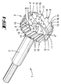
- Fig. 1 designed as a Forstner drill cylinder head drill 1, which essentially consists of a Clamping shank 2 and a drill head carried by this 3 composed.
- the latter is essentially circular cylindrical and has an essentially diametrically over the entire circular cross-section extending main cutting edge 4 with a centering tip 5.
- the main cutting edge 4 is through the centering tip 5 interrupted, with each major cutting section 4 'and 4' 'towards the outer wall 6 of the drill head 3 Open chip channel penetrating the drill head 3 at an angle 7 connects.
- Each outer wall end of the main cutting edge 4 one closes with the circumference of the drill head 3 coincident pre-cut edge 8, which for Guidance of the drill 1 is used.
- Each pre-cut edge 8 extends from the end of the main cutting edge 4 to to the edge of the other chip channel 7. Conditional due to the essentially circular cylindrical design the drill head 3 thus result in a cylindrical shape curved pre-cut edges 8.
- the rear of the jacket wall 6 is assigned in each case a pre-cut edge 8 a hollow surface 9 is formed. This results in one, the pre-cut edge 8 forming, arcuate roughing cutter 10 with a wedge-shaped cross-sectional shape (cf. Fig. 4).
- the main cutting edge 4 or the main cutting edge sections 4 'and 4' ' have free cut surfaces 11, which are flat and continuously up to the hollow surface 9 of each in the direction of rotation following pre-cutter 10, the open spaces 11 with respect to a transverse plane of the Drill head 3 inclined by an angle of approx. 30 ° each are.
- the chip channels 7 have an arcuate rounded Chip channel base. Each chip channel 7 projects into the drill head its associated main cutting edge section 4 ' and 4 ''. The arched chip channel base protrudes here to the free area 11 of the other main cutting edge section inside.
- the planes of the free cut surfaces 11 essentially cut the respective hollow surface 9 in a right Angle.
- the otherwise smooth-walled jacket wall 6 is in the 1 to 4 shown first embodiment interrupted by grooves 12 of circular arc shape in cross section. As a result, radial bulges 13 are formed, which in this first embodiment Form shell wall recesses.
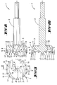
- the grooves 12 are, for example, by means of one Finger cutter or the like in the jacket wall 6 incorporated, the orientation of the grooves 12 so can be chosen to be parallel to the drill axis run x-x. However, as can be seen in particular in FIG. 2, an orientation is preferred in which the Grooves 12 are aligned inclined to the axis x-x. By doing The embodiment shown here is an angle alpha of approx. 20 °.
- the grooves 12 are open on both sides, that means they extend in the axial direction considered total drill head height, which is due to the wedge-shaped cross-section of the pre-cutter 10 isolated, tooth-like pre-cutter segments 14 train.
- In the area of the penetration of grooves 12 and pre-cutters 10 are elliptical Open cuts 15.
- each pre-cut edge 8 is in the area between two adjacent grooves 12, that is in the area of one Pre-cutting segment 14 provided with a free cut 16, with which the pre-cut edges 8 only selectively touch the workpiece to be machined.
- a Forstner drill 1 is shown, which is the same the first embodiment with bulges 13 in Form of grooves 12 provided in the region of the jacket wall 6 is. However, here is an essentially rectangular one Cross-sectional shape of the grooves 12 selected. Are further the grooves 12 aligned parallel to the drill axis x-x.
- These grooves 12 are also open on both sides, which in turn is in the area of the pre-cut edges 8 isolated, tooth-like pre-cutter segments 14 train.
- Free cuts 15 formed.
- the bulges 13 and grooves 12 are continuous, that means open on both sides. It However, versions are also conceivable in which the Bulges 13 closed on one or both sides are trained.
- the bulges 13 and grooves 12 only serve to reduce the heat development in the area of the drill head 3 and not for chip evacuation. The latter takes place over the essentially centrally arranged Chip channels 7. This can result in the formation and alignment of the bulges 13 freely chosen will.
- FIGS. 8 to 10 A third embodiment of the invention Solution is shown in FIGS. 8 to 10. opposite the previously described embodiments are here the jacket wall 6 of the drill head 3 is not groove-like Bulges interrupted. Rather is training chosen here so that the bulges 13 from radial protruding tooth sections of individual teeth 17 are formed are. Accordingly, the jacket wall 6 is not of Depressions but interrupted by protrusions.
- the individual teeth 17 consist of a hard material and are accommodated in pockets 18 of the drill head 3.
- the receiving pockets 18 are in the radial outside area the pre-cutter 10 for the outer casing wall and End face of the drill head 3 is open, and have a dovetail-shaped cross section.
- the individual teeth 17 have an insertion cross section the receiving pockets 18 adapted cross-section on.
- the axial length and the radial depth each receiving pocket 18 is selected so that a inserted single tooth 17 with radial projection a and axial projection b is supported.
Landscapes
- Life Sciences & Earth Sciences (AREA)
- Engineering & Computer Science (AREA)
- Mechanical Engineering (AREA)
- Wood Science & Technology (AREA)
- Forests & Forestry (AREA)
- Drilling Tools (AREA)
- Earth Drilling (AREA)
- Processing Of Stones Or Stones Resemblance Materials (AREA)
- Drilling And Boring (AREA)
- Cylinder Crankcases Of Internal Combustion Engines (AREA)
Applications Claiming Priority (2)
| Application Number | Priority Date | Filing Date | Title |
|---|---|---|---|
| DE19702423 | 1997-01-24 | ||
| DE19702423A DE19702423B4 (de) | 1997-01-24 | 1997-01-24 | Zylinderkopfbohrer |
Publications (3)
| Publication Number | Publication Date |
|---|---|
| EP0855257A2 true EP0855257A2 (fr) | 1998-07-29 |
| EP0855257A3 EP0855257A3 (fr) | 1999-07-14 |
| EP0855257B1 EP0855257B1 (fr) | 2000-08-16 |
Family
ID=7818209
Family Applications (1)
| Application Number | Title | Priority Date | Filing Date |
|---|---|---|---|
| EP97122890A Expired - Lifetime EP0855257B1 (fr) | 1997-01-24 | 1997-12-24 | Mèche avec tête cylindrique |
Country Status (7)
| Country | Link |
|---|---|
| US (1) | US5975814A (fr) |
| EP (1) | EP0855257B1 (fr) |
| AT (1) | ATE195457T1 (fr) |
| CA (1) | CA2227820C (fr) |
| DE (2) | DE19702423B4 (fr) |
| DK (1) | DK0855257T3 (fr) |
| ES (1) | ES2151221T3 (fr) |
Cited By (4)
| Publication number | Priority date | Publication date | Assignee | Title |
|---|---|---|---|---|
| WO2001064407A1 (fr) * | 2000-03-03 | 2001-09-07 | Johann Eberhard Gesellschaft M.B.H. | Meche, en particulier meche forstner ou a tete de centrage |
| US6644899B2 (en) | 2000-03-03 | 2003-11-11 | Johann Eberhard Gesellschaft M.B.H. | Drill bit and process of producing a drill bit with improved cutting edges |
| US7648316B2 (en) | 2006-01-26 | 2010-01-19 | Wolfcraft, Gmbh | Forstner drill bit |
| EP4215305A1 (fr) | 2022-01-25 | 2023-07-26 | KSB SE & Co. KGaA | Outil rotatif à porte-outil |
Families Citing this family (25)
| Publication number | Priority date | Publication date | Assignee | Title |
|---|---|---|---|---|
| AT409600B (de) * | 2000-03-03 | 2002-09-25 | Johann Eberhard Ges M B H | Bohrer |
| AT4227U1 (de) * | 2000-03-03 | 2001-04-25 | Johann Eberhard Ges M B H | Bohrer |
| US6354774B1 (en) | 2000-04-27 | 2002-03-12 | The Mibro Group | Forstner drill bit |
| US6612788B2 (en) | 2001-03-30 | 2003-09-02 | Black & Decker Inc. | Self-feed wood bit |
| US6874978B2 (en) * | 2002-03-25 | 2005-04-05 | Milwaukee Electric Tool Corporation | Boring bit and methods for manufacturing boring bits |
| US20060216123A1 (en) * | 2005-03-24 | 2006-09-28 | Burdick Brett W | Flat bit sphere named the V-back paddlesphere bit |
| US7909547B2 (en) * | 2005-10-08 | 2011-03-22 | Milwaukee Electric Tool Corporation | Replaceable tip for a bit or auger bit |
| DE102007002530B4 (de) * | 2006-01-26 | 2016-03-03 | Wolfcraft Gmbh | Forstnerbohrer |
| US8328477B2 (en) * | 2006-03-02 | 2012-12-11 | Milwaukee Electric Tool Corporation | Cutting tool |
| US7661911B2 (en) * | 2006-03-02 | 2010-02-16 | Milwaukee Electric Tool Corporation | Cutting tool |
| DE102006039426B4 (de) * | 2006-08-23 | 2008-08-28 | Horst Miebach Gmbh | Holzbohrer |
| USD605672S1 (en) | 2007-03-01 | 2009-12-08 | Milwaukee Electric Tool Corporation | Cutting blade |
| USD575808S1 (en) | 2007-03-02 | 2008-08-26 | Milwaukee Electric Tool Corporation | Cutting tool |
| US8070398B2 (en) * | 2008-02-19 | 2011-12-06 | Irwin Industrial Tool Company | Multi-blade self feed bit |
| USD607024S1 (en) | 2008-09-12 | 2009-12-29 | Robert Bosch Gmbh | Hinge boring bit |
| US8727679B2 (en) * | 2009-09-10 | 2014-05-20 | Techtronic Power Tools Technology Limited | Wood boring bit |
| USD649569S1 (en) | 2009-09-10 | 2011-11-29 | Techtronic Power Tools Technology Limited | Wood boring bit |
| CN205218137U (zh) | 2013-02-01 | 2016-05-11 | 米沃奇电动工具公司 | 具有可替换钻头的螺旋钻头 |
| US20160345619A1 (en) * | 2014-12-02 | 2016-12-01 | Monarch Media Llc. | Coconut removal device and method therefor |
| US11317647B2 (en) * | 2014-12-02 | 2022-05-03 | Monarch Media, Llc | Coconut water removal device and method therefor |
| DE202016001386U1 (de) | 2016-03-04 | 2016-03-17 | FAMAG-Werkzeugfabrik GmbH & Co. KG | Zylinderkopfbohrer |
| US11123808B2 (en) | 2016-10-07 | 2021-09-21 | Mapal Fabrik Fur Prazisionswerkzeuge Dr. Kress Kg | Metal drilling tool |
| CN108972901A (zh) * | 2018-07-17 | 2018-12-11 | 温州市人民医院 | 一种墙壁开孔器 |
| NL2024154B1 (en) | 2019-11-04 | 2021-07-19 | Colt Tech Gmbh | Cylindrical head boring tool, in particular a Forstner bit |
| USD1066442S1 (en) * | 2022-06-07 | 2025-03-11 | Apex Brands, Inc. | Self-feed bit |
Family Cites Families (12)
| Publication number | Priority date | Publication date | Assignee | Title |
|---|---|---|---|---|
| US2613710A (en) * | 1951-08-02 | 1952-10-14 | Cleveland Twist Drill Co | Machine bit for drilling wood |
| DE2005775A1 (de) * | 1970-02-09 | 1971-08-19 | Wolfcraft Robert Wolff Kg, 5441 Weibern | Zylinderkopfbohrer |
| US4090807A (en) * | 1976-09-20 | 1978-05-23 | Stewart Arthur A | Axially supported boring tool and method for making same |
| DE2842423A1 (de) * | 1978-09-29 | 1980-04-17 | Heinrich Reineke | Rundlochbohrer mit auswechselbaren schneiden |
| SE454757B (sv) * | 1984-08-08 | 1988-05-30 | Lars Ove Jansson | Installationsborr |
| DE3719758A1 (de) * | 1987-06-15 | 1989-01-05 | Weber Gustav Schlagring | Bohrer |
| DE3824502A1 (de) * | 1988-07-20 | 1990-01-25 | Hilti Ag | Hohlbohrwerkzeug |
| US5193951A (en) * | 1988-08-24 | 1993-03-16 | Vermont American Corporation | Wood-drilling bit |
| DE4115030C1 (fr) * | 1991-05-08 | 1992-06-25 | Famag-Werkzeugfabrik Friedr. Aug. Muehlhoff, 5630 Remscheid, De | |
| US5499667A (en) * | 1994-06-21 | 1996-03-19 | Nakanishi Construction Company | Drill/cutting bit, and method of making structural joint |
| DE19602903A1 (de) * | 1995-04-27 | 1996-10-31 | Hawera Probst Kg Hartmetall | Bohrkronenrohr |
| DE29701161U1 (de) * | 1997-01-24 | 1998-05-28 | FAMAG-Werkzeugfabrik Friedr. Aug. Mühlhoff, 42855 Remscheid | Zylinderkopfbohrer |
-
1997
- 1997-01-24 DE DE19702423A patent/DE19702423B4/de not_active Expired - Lifetime
- 1997-12-24 ES ES97122890T patent/ES2151221T3/es not_active Expired - Lifetime
- 1997-12-24 AT AT97122890T patent/ATE195457T1/de active
- 1997-12-24 DE DE59702198T patent/DE59702198D1/de not_active Expired - Lifetime
- 1997-12-24 DK DK97122890T patent/DK0855257T3/da active
- 1997-12-24 EP EP97122890A patent/EP0855257B1/fr not_active Expired - Lifetime
-
1998
- 1998-01-21 US US09/010,210 patent/US5975814A/en not_active Expired - Fee Related
- 1998-01-23 CA CA002227820A patent/CA2227820C/fr not_active Expired - Lifetime
Cited By (5)
| Publication number | Priority date | Publication date | Assignee | Title |
|---|---|---|---|---|
| WO2001064407A1 (fr) * | 2000-03-03 | 2001-09-07 | Johann Eberhard Gesellschaft M.B.H. | Meche, en particulier meche forstner ou a tete de centrage |
| US6644899B2 (en) | 2000-03-03 | 2003-11-11 | Johann Eberhard Gesellschaft M.B.H. | Drill bit and process of producing a drill bit with improved cutting edges |
| US7648316B2 (en) | 2006-01-26 | 2010-01-19 | Wolfcraft, Gmbh | Forstner drill bit |
| EP4215305A1 (fr) | 2022-01-25 | 2023-07-26 | KSB SE & Co. KGaA | Outil rotatif à porte-outil |
| DE102022101647A1 (de) | 2022-01-25 | 2023-07-27 | KSB SE & Co. KGaA | Rotierendes Trägerwerkzeug |
Also Published As
| Publication number | Publication date |
|---|---|
| DE59702198D1 (de) | 2000-09-21 |
| DE19702423A1 (de) | 1998-08-06 |
| ES2151221T3 (es) | 2000-12-16 |
| EP0855257A3 (fr) | 1999-07-14 |
| CA2227820A1 (fr) | 1998-07-24 |
| CA2227820C (fr) | 2001-10-23 |
| ATE195457T1 (de) | 2000-09-15 |
| EP0855257B1 (fr) | 2000-08-16 |
| DE19702423B4 (de) | 2009-11-12 |
| US5975814A (en) | 1999-11-02 |
| DK0855257T3 (da) | 2000-12-18 |
Similar Documents
| Publication | Publication Date | Title |
|---|---|---|
| EP0855257B1 (fr) | Mèche avec tête cylindrique | |
| DE102008004564B4 (de) | Bohrwerkzeug mit Ausspitzung | |
| DE2851183C2 (de) | Wendelbohrer | |
| EP2138255B1 (fr) | Dispositif de forage à trépan | |
| DE69000356T2 (de) | Fluegel-bohrschraube. | |
| DE102005014422B4 (de) | Bohrgewindefräser | |
| DE60016782T2 (de) | Selbstbohrender ankerbolzen | |
| EP0841875B1 (fr) | Tete de percage de canaux dans des os | |
| DE60106587T2 (de) | Schlagbohrmeissel | |
| DE102009012725A1 (de) | Bohrerspitze sowie Bohrwerkzeug mit einer Bohrerspitze | |
| DE3510048C1 (de) | Schlagbohrkrone fuer Gesteinsbohrmaschinen | |
| DE102007050050A1 (de) | Rundlaufwerkzeug, insbesondere Bohrer | |
| DE69510794T2 (de) | Bohrwerkzeug mit ausnehmungen für abgerundete schneideinsätze | |
| WO1991006387A1 (fr) | Foret helicoidal | |
| EP2138125B2 (fr) | foret utilisé dans l'implantologie dentaire | |
| DE3500261A1 (de) | Gewinnungswerkzeug | |
| EP1387923B1 (fr) | Couronne de sondage | |
| EP0147830A2 (fr) | Foret pour perceuses tenues à la main | |
| DE102010010589B4 (de) | Dental- oder chirurgisches Werkzeug | |
| DE19807609A1 (de) | Spiralbohrer | |
| DE2056091C3 (de) | Spitzbohrwerkzeug | |
| EP1083294B1 (fr) | Outil de forage | |
| EP1083295A1 (fr) | Outil de forage | |
| DE112019006105T5 (de) | Bohrer und Einsatz für Bohrer mit verbesserter Zentrierfähigkeit und Schneidleistung | |
| EP0240765A2 (fr) | Foret hélicoidal en carbure avec des canaux de refroidissement intérieur |
Legal Events
| Date | Code | Title | Description |
|---|---|---|---|
| PUAI | Public reference made under article 153(3) epc to a published international application that has entered the european phase |
Free format text: ORIGINAL CODE: 0009012 |
|
| AK | Designated contracting states |
Kind code of ref document: A2 Designated state(s): AT BE CH DE DK ES FI FR GB GR IT LI NL PT SE |
|
| AX | Request for extension of the european patent |
Free format text: AL;LT;LV;MK;RO;SI |
|
| PUAL | Search report despatched |
Free format text: ORIGINAL CODE: 0009013 |
|
| AK | Designated contracting states |
Kind code of ref document: A3 Designated state(s): AT BE CH DE DK ES FI FR GB GR IE IT LI LU MC NL PT SE |
|
| AX | Request for extension of the european patent |
Free format text: AL;LT;LV;MK;RO;SI |
|
| 17P | Request for examination filed |
Effective date: 19990728 |
|
| GRAG | Despatch of communication of intention to grant |
Free format text: ORIGINAL CODE: EPIDOS AGRA |
|
| 17Q | First examination report despatched |
Effective date: 19991115 |
|
| GRAG | Despatch of communication of intention to grant |
Free format text: ORIGINAL CODE: EPIDOS AGRA |
|
| GRAG | Despatch of communication of intention to grant |
Free format text: ORIGINAL CODE: EPIDOS AGRA |
|
| GRAH | Despatch of communication of intention to grant a patent |
Free format text: ORIGINAL CODE: EPIDOS IGRA |
|
| AKX | Designation fees paid |
Free format text: AT BE CH DE DK ES FI FR GB GR IT LI NL PT SE |
|
| AXX | Extension fees paid |
Free format text: SI PAYMENT 19991207 |
|
| GRAH | Despatch of communication of intention to grant a patent |
Free format text: ORIGINAL CODE: EPIDOS IGRA |
|
| GRAA | (expected) grant |
Free format text: ORIGINAL CODE: 0009210 |
|
| AK | Designated contracting states |
Kind code of ref document: B1 Designated state(s): AT BE CH DE DK ES FI FR GB GR IT LI NL PT SE |
|
| AX | Request for extension of the european patent |
Free format text: SI PAYMENT 19991207 |
|
| PG25 | Lapsed in a contracting state [announced via postgrant information from national office to epo] |
Ref country code: GR Free format text: LAPSE BECAUSE OF NON-PAYMENT OF DUE FEES Effective date: 20000816 Ref country code: FI Free format text: LAPSE BECAUSE OF FAILURE TO SUBMIT A TRANSLATION OF THE DESCRIPTION OR TO PAY THE FEE WITHIN THE PRESCRIBED TIME-LIMIT Effective date: 20000816 |
|
| REF | Corresponds to: |
Ref document number: 195457 Country of ref document: AT Date of ref document: 20000915 Kind code of ref document: T |
|
| REG | Reference to a national code |
Ref country code: CH Ref legal event code: EP |
|
| REF | Corresponds to: |
Ref document number: 59702198 Country of ref document: DE Date of ref document: 20000921 |
|
| ITF | It: translation for a ep patent filed | ||
| PG25 | Lapsed in a contracting state [announced via postgrant information from national office to epo] |
Ref country code: PT Free format text: LAPSE BECAUSE OF FAILURE TO SUBMIT A TRANSLATION OF THE DESCRIPTION OR TO PAY THE FEE WITHIN THE PRESCRIBED TIME-LIMIT Effective date: 20001116 |
|
| ET | Fr: translation filed | ||
| REG | Reference to a national code |
Ref country code: ES Ref legal event code: FG2A Ref document number: 2151221 Country of ref document: ES Kind code of ref document: T3 |
|
| REG | Reference to a national code |
Ref country code: DK Ref legal event code: T3 |
|
| GBT | Gb: translation of ep patent filed (gb section 77(6)(a)/1977) |
Effective date: 20001208 |
|
| PLBE | No opposition filed within time limit |
Free format text: ORIGINAL CODE: 0009261 |
|
| STAA | Information on the status of an ep patent application or granted ep patent |
Free format text: STATUS: NO OPPOSITION FILED WITHIN TIME LIMIT |
|
| 26N | No opposition filed | ||
| REG | Reference to a national code |
Ref country code: GB Ref legal event code: IF02 |
|
| PG25 | Lapsed in a contracting state [announced via postgrant information from national office to epo] |
Ref country code: NL Free format text: LAPSE BECAUSE OF NON-PAYMENT OF DUE FEES Effective date: 20020701 |
|
| NLV4 | Nl: lapsed or anulled due to non-payment of the annual fee |
Effective date: 20020701 |
|
| NLXE | Nl: other communications concerning ep-patents (part 3 heading xe) |
Free format text: A REQUEST FOR RESTORATION TO THE PRIOR STATE (ARTICLE 23 OF THE PATENTS ACT 1995) HAS BEEN FILED ON 20021224/12. |
|
| NLXE | Nl: other communications concerning ep-patents (part 3 heading xe) |
Free format text: THE REQUEST FOR RESTORATION TO THE PRIOR STATE AS PROVIDED FOR IN ARTICLE 23 OF THE PATENTS ACT 1995 (SEE PUBLICATION IN HEADING XE OF THE PATENT BULLETIN OF 20030303/03) HAS BEEN REJECTED. |
|
| BERE | Be: lapsed |
Owner name: *FAMAG-WERKZEUGFABRIK FRIEDRICH AUG. MUHLHOFF Effective date: 20101231 |
|
| REG | Reference to a national code |
Ref country code: FR Ref legal event code: PLFP Year of fee payment: 19 |
|
| PGFP | Annual fee paid to national office [announced via postgrant information from national office to epo] |
Ref country code: GB Payment date: 20151217 Year of fee payment: 19 Ref country code: DK Payment date: 20151215 Year of fee payment: 19 |
|
| PGFP | Annual fee paid to national office [announced via postgrant information from national office to epo] |
Ref country code: SE Payment date: 20151217 Year of fee payment: 19 Ref country code: FR Payment date: 20151211 Year of fee payment: 19 Ref country code: ES Payment date: 20151210 Year of fee payment: 19 Ref country code: BE Payment date: 20151215 Year of fee payment: 19 |
|
| PG25 | Lapsed in a contracting state [announced via postgrant information from national office to epo] |
Ref country code: BE Free format text: THE PATENT HAS BEEN ANNULLED BY A DECISION OF A NATIONAL AUTHORITY Effective date: 20101231 |
|
| PGFP | Annual fee paid to national office [announced via postgrant information from national office to epo] |
Ref country code: CH Payment date: 20161213 Year of fee payment: 20 |
|
| PGFP | Annual fee paid to national office [announced via postgrant information from national office to epo] |
Ref country code: AT Payment date: 20161220 Year of fee payment: 20 Ref country code: IT Payment date: 20161130 Year of fee payment: 20 |
|
| PGFP | Annual fee paid to national office [announced via postgrant information from national office to epo] |
Ref country code: DE Payment date: 20170224 Year of fee payment: 20 |
|
| PG25 | Lapsed in a contracting state [announced via postgrant information from national office to epo] |
Ref country code: BE Free format text: THE PATENT HAS BEEN ANNULLED BY A DECISION OF A NATIONAL AUTHORITY Effective date: 20161231 |
|
| REG | Reference to a national code |
Ref country code: DK Ref legal event code: EBP Effective date: 20161231 |
|
| REG | Reference to a national code |
Ref country code: SE Ref legal event code: EUG |
|
| GBPC | Gb: european patent ceased through non-payment of renewal fee |
Effective date: 20161224 |
|
| PG25 | Lapsed in a contracting state [announced via postgrant information from national office to epo] |
Ref country code: SE Free format text: LAPSE BECAUSE OF NON-PAYMENT OF DUE FEES Effective date: 20161225 |
|
| REG | Reference to a national code |
Ref country code: FR Ref legal event code: ST Effective date: 20170831 |
|
| PG25 | Lapsed in a contracting state [announced via postgrant information from national office to epo] |
Ref country code: FR Free format text: LAPSE BECAUSE OF NON-PAYMENT OF DUE FEES Effective date: 20170102 |
|
| PG25 | Lapsed in a contracting state [announced via postgrant information from national office to epo] |
Ref country code: GB Free format text: LAPSE BECAUSE OF NON-PAYMENT OF DUE FEES Effective date: 20161224 |
|
| REG | Reference to a national code |
Ref country code: DE Ref legal event code: R071 Ref document number: 59702198 Country of ref document: DE |
|
| REG | Reference to a national code |
Ref country code: CH Ref legal event code: PL |
|
| PG25 | Lapsed in a contracting state [announced via postgrant information from national office to epo] |
Ref country code: DK Free format text: LAPSE BECAUSE OF NON-PAYMENT OF DUE FEES Effective date: 20161231 |
|
| REG | Reference to a national code |
Ref country code: BE Ref legal event code: MM Effective date: 20161231 |
|
| REG | Reference to a national code |
Ref country code: AT Ref legal event code: MK07 Ref document number: 195457 Country of ref document: AT Kind code of ref document: T Effective date: 20171224 |
|
| REG | Reference to a national code |
Ref country code: ES Ref legal event code: FD2A Effective date: 20180507 |
|
| PG25 | Lapsed in a contracting state [announced via postgrant information from national office to epo] |
Ref country code: ES Free format text: LAPSE BECAUSE OF FAILURE TO SUBMIT A TRANSLATION OF THE DESCRIPTION OR TO PAY THE FEE WITHIN THE PRESCRIBED TIME-LIMIT Effective date: 20000816 |
|
| PG25 | Lapsed in a contracting state [announced via postgrant information from national office to epo] |
Ref country code: ES Free format text: LAPSE BECAUSE OF FAILURE TO SUBMIT A TRANSLATION OF THE DESCRIPTION OR TO PAY THE FEE WITHIN THE PRESCRIBED TIME-LIMIT Effective date: 20161225 |
|
| RIC2 | Information provided on ipc code assigned after grant |
Ipc: B27G 15/00 20060101AFI19980506BHEP |