EP0855262A2 - Procédé et appareil d'étanchéification pour l'interstice annuliare entre deux surfaces d'étanchéité annulaires, notamment pour de machines à extruder - Google Patents
Procédé et appareil d'étanchéification pour l'interstice annuliare entre deux surfaces d'étanchéité annulaires, notamment pour de machines à extruder Download PDFInfo
- Publication number
- EP0855262A2 EP0855262A2 EP98100656A EP98100656A EP0855262A2 EP 0855262 A2 EP0855262 A2 EP 0855262A2 EP 98100656 A EP98100656 A EP 98100656A EP 98100656 A EP98100656 A EP 98100656A EP 0855262 A2 EP0855262 A2 EP 0855262A2
- Authority
- EP
- European Patent Office
- Prior art keywords
- ring
- sealing
- sealing surface
- force
- edge
- Prior art date
- Legal status (The legal status is an assumption and is not a legal conclusion. Google has not performed a legal analysis and makes no representation as to the accuracy of the status listed.)
- Granted
Links
- 238000007789 sealing Methods 0.000 title claims abstract description 151
- 238000000034 method Methods 0.000 title claims description 4
- 239000000463 material Substances 0.000 claims abstract description 13
- 238000003825 pressing Methods 0.000 claims description 16
- 238000001125 extrusion Methods 0.000 claims description 15
- 239000002184 metal Substances 0.000 claims description 9
- 238000000465 moulding Methods 0.000 claims description 4
- 239000004033 plastic Substances 0.000 claims description 3
- 229920003023 plastic Polymers 0.000 claims description 3
- 239000002905 metal composite material Substances 0.000 claims description 2
- 238000006073 displacement reaction Methods 0.000 description 5
- 239000007921 spray Substances 0.000 description 5
- 230000005540 biological transmission Effects 0.000 description 4
- 230000000694 effects Effects 0.000 description 3
- 238000005516 engineering process Methods 0.000 description 2
- 238000004519 manufacturing process Methods 0.000 description 2
- 230000003716 rejuvenation Effects 0.000 description 2
- 230000007704 transition Effects 0.000 description 2
- 238000004140 cleaning Methods 0.000 description 1
- 230000009969 flowable effect Effects 0.000 description 1
- 238000002347 injection Methods 0.000 description 1
- 239000007924 injection Substances 0.000 description 1
- 230000002093 peripheral effect Effects 0.000 description 1
Images



Classifications
-
- B—PERFORMING OPERATIONS; TRANSPORTING
- B29—WORKING OF PLASTICS; WORKING OF SUBSTANCES IN A PLASTIC STATE IN GENERAL
- B29C—SHAPING OR JOINING OF PLASTICS; SHAPING OF MATERIAL IN A PLASTIC STATE, NOT OTHERWISE PROVIDED FOR; AFTER-TREATMENT OF THE SHAPED PRODUCTS, e.g. REPAIRING
- B29C48/00—Extrusion moulding, i.e. expressing the moulding material through a die or nozzle which imparts the desired form; Apparatus therefor
- B29C48/25—Component parts, details or accessories; Auxiliary operations
- B29C48/36—Means for plasticising or homogenising the moulding material or forcing it through the nozzle or die
- B29C48/50—Details of extruders
- B29C48/69—Filters or screens for the moulding material
- B29C48/691—Arrangements for replacing filters, e.g. with two parallel filters for alternate use
- B29C48/6912—Arrangements for replacing filters, e.g. with two parallel filters for alternate use the filters being fitted on a single rectilinearly reciprocating slide
-
- B—PERFORMING OPERATIONS; TRANSPORTING
- B29—WORKING OF PLASTICS; WORKING OF SUBSTANCES IN A PLASTIC STATE IN GENERAL
- B29C—SHAPING OR JOINING OF PLASTICS; SHAPING OF MATERIAL IN A PLASTIC STATE, NOT OTHERWISE PROVIDED FOR; AFTER-TREATMENT OF THE SHAPED PRODUCTS, e.g. REPAIRING
- B29C48/00—Extrusion moulding, i.e. expressing the moulding material through a die or nozzle which imparts the desired form; Apparatus therefor
- B29C48/03—Extrusion moulding, i.e. expressing the moulding material through a die or nozzle which imparts the desired form; Apparatus therefor characterised by the shape of the extruded material at extrusion
- B29C48/09—Articles with cross-sections having partially or fully enclosed cavities, e.g. pipes or channels
-
- B—PERFORMING OPERATIONS; TRANSPORTING
- B29—WORKING OF PLASTICS; WORKING OF SUBSTANCES IN A PLASTIC STATE IN GENERAL
- B29C—SHAPING OR JOINING OF PLASTICS; SHAPING OF MATERIAL IN A PLASTIC STATE, NOT OTHERWISE PROVIDED FOR; AFTER-TREATMENT OF THE SHAPED PRODUCTS, e.g. REPAIRING
- B29C48/00—Extrusion moulding, i.e. expressing the moulding material through a die or nozzle which imparts the desired form; Apparatus therefor
- B29C48/03—Extrusion moulding, i.e. expressing the moulding material through a die or nozzle which imparts the desired form; Apparatus therefor characterised by the shape of the extruded material at extrusion
- B29C48/13—Articles with a cross-section varying in the longitudinal direction, e.g. corrugated pipes
-
- B—PERFORMING OPERATIONS; TRANSPORTING
- B29—WORKING OF PLASTICS; WORKING OF SUBSTANCES IN A PLASTIC STATE IN GENERAL
- B29C—SHAPING OR JOINING OF PLASTICS; SHAPING OF MATERIAL IN A PLASTIC STATE, NOT OTHERWISE PROVIDED FOR; AFTER-TREATMENT OF THE SHAPED PRODUCTS, e.g. REPAIRING
- B29C48/00—Extrusion moulding, i.e. expressing the moulding material through a die or nozzle which imparts the desired form; Apparatus therefor
- B29C48/25—Component parts, details or accessories; Auxiliary operations
- B29C48/254—Sealing means
-
- B—PERFORMING OPERATIONS; TRANSPORTING
- B29—WORKING OF PLASTICS; WORKING OF SUBSTANCES IN A PLASTIC STATE IN GENERAL
- B29C—SHAPING OR JOINING OF PLASTICS; SHAPING OF MATERIAL IN A PLASTIC STATE, NOT OTHERWISE PROVIDED FOR; AFTER-TREATMENT OF THE SHAPED PRODUCTS, e.g. REPAIRING
- B29C48/00—Extrusion moulding, i.e. expressing the moulding material through a die or nozzle which imparts the desired form; Apparatus therefor
- B29C48/25—Component parts, details or accessories; Auxiliary operations
- B29C48/254—Sealing means
- B29C48/2545—Sealing means for filters
-
- Y—GENERAL TAGGING OF NEW TECHNOLOGICAL DEVELOPMENTS; GENERAL TAGGING OF CROSS-SECTIONAL TECHNOLOGIES SPANNING OVER SEVERAL SECTIONS OF THE IPC; TECHNICAL SUBJECTS COVERED BY FORMER USPC CROSS-REFERENCE ART COLLECTIONS [XRACs] AND DIGESTS
- Y10—TECHNICAL SUBJECTS COVERED BY FORMER USPC
- Y10S—TECHNICAL SUBJECTS COVERED BY FORMER USPC CROSS-REFERENCE ART COLLECTIONS [XRACs] AND DIGESTS
- Y10S277/00—Seal for a joint or juncture
- Y10S277/924—Deformation, material removal, or molding for manufacture of seal
Definitions
- the invention relates to methods and devices for Sealing an annular gap between two sealing surfaces machine parts using a ring attached to them bears against both sealing surfaces, particularly on extrusion machines, where this seal preferably at Screen and tool changing devices their importance Has.
- the sieves must be cleaned from time to time. Around do not interrupt production for cleaning sieve changing devices have been developed which e.g. between extruder and spray head are built into the extrusion system. These exist from individual sieve cassettes or a slide at least two screens and means for a quick one Displacement of this sieve cassette or this slide in their working positions. Because of the high, at the place of Siebe occurring pressures causes problems in operation with high contact pressures in the area of the seal to achieve a perfect seal, the high Contact pressures for the displacement of the slide briefly to the extent that the slide or the Sieve cassettes without being damaged and without Damage to the seal used can be moved can to them after moving the slider with the sieves or the sieve cassettes again immediately to take effect.
- the invention avoids the disadvantages of the prior art Technology. It is the object of the invention with simple Means a very simple compact To create a seal even at very high pressures seals perfectly and yet easy to relieve is when one machine part is moved against the other shall be.
- the invention is that either one preferably a substantially flat ring from a elastic but very strong material used, the preferably protrudes on one side beyond its sealing surface, that you can press this ring on one side beyond this sealing surface part of the Ring so deformed that it bulges and thereby with its one edge on one sealing surface creates a ring line and on the other sealing surface is supported in a ring line or that you have a curved or slightly frustoconical ring from one elastic but very strong material used, the protrudes at least on one side beyond the sealing surface, that you seal this ring under pressure between the leaves both sealing surfaces and one Border edge on one sealing surface in a ring shape can rest and on the other sealing surface can be supported in the form of a ring line, and that by Force transmission on the protruding beyond the sealing surface Part of the ring deformed this ring so that he loses his curvature and stretches the line system on one sealing surface loses.
- a seal is formed by two ring lines Sealing surfaces achieved where the surface pressure and so the sealing effect is very high.
- the ring is deformed to seal it to achieve, in the other, second case the ring deformed to the sealing effect and ring-shaped Remove pressure on one side around the sieve cassette or to be able to move the slider.
- This seal can be used wherever a gap is to be sealed, which is slightly larger than the thickness of the sealing part of the ring.
- the device according to the invention is designed such that the ring in the area between the two ring-shaped Is essentially flat and through Force transmission on the protruding beyond the sealing surface Part is warped so that the two ring-shaped contact surfaces of the ring with pressure rest on the sealing surfaces.
- the invention is Device designed so that the ring made of an elastic, but very strong material is that the Ring protrudes at least on one side beyond its sealing surface, that the ring is due to force the one protruding on one side beyond its sealing surface Part deformed so that it bulges, and that the ring with its one edge on one Sealing surface rests in a ring line and on the other sealing surface is supported in a ring shape.
- the other design option is characterized by this that the ring at least in the area between the arched two ring-shaped contact surfaces or is shaped like a truncated cone that the two ring-shaped Contact surfaces with force transmission to the Apply sealing surfaces and by pressing on the Sealing surface protruding part of the ring at least in the area between the two ring-shaped contact surfaces is deformable into a plane, whereby by Force transmission on the protruding beyond the sealing surface Part of the ring deformed this ring so that he loses his curvature and stretches the line system on one sealing surface loses.
- the ring made of metal, a high-strength plastic or a metal composite is made.
- the part of the ring intended to apply force can be turned outside or inside the sealing surface protrude: is a surface behind to seal the outside is the one to apply force intended part of the ring outside, is a Opening or to seal a hole is located the part of the ring intended to apply force inside the hole.
- the ring can have a uniform material thickness, however, it can be advantageous for the ring to have a Part of uniform ring thickness and one in his Thick tapered portion that extends up to the extends an edge of the ring, and that on the tapering part of the ring a pressing device works. This is done in order to be sufficient with a flat contact surface Free space for pressing the ring in his to gain part protruding beyond the sealing surface
- a particular advantage of this sealing device is that the ring and thus the sealing surface any Shapes that the ring e.g. circular, oval, essentially rectangular (with curves on the corners) or essentially square (with curves) at the corners).
- the bolts can be hydraulic Force applied and preferably the Pistons or piston rods of hydraulic cylinders.
- the bolt with mechanically generated force preferably the force a spindle of an eccentric, a wedge, one Round wedge or a screw nut.
- a uniform application can be achieved that the bolts are attached to a ring which can be moved with hydraulic or mechanical force is.
- the ring can be hydraulic through the ring piston Pressing device can be pressurized.
- this sealing device is particularly advantageous for sealing a sieve or one with a slide provided with a screen changing device an extrusion system or for sealing a molding tool or one with molding tools provided slide of a tool changing device an extrusion line.
- the application of force on one side via the sealing surface protruding part of the ring can also become undesirable Lead tension in the ring. Leave this through slots in the one-sided over the sealing surface protruding part of the ring, its direction preferably runs radially away from the sealing surface.
- the sealing device shown in Fig. 1 takes place Use on extrusion machines, primarily for Sealing the slide of a screen changing device, but can also be used in other places, e.g. for connections for a spray head changer and other attachments.
- the sealing device consists of a ring 7, between two flat surfaces facing each other 8.9 of the machine parts counterpart 2 and component 6 arranged and from an arrow Force application device 10 in the component 6 between extruder 1 and slide 4 or in the extruder 1 is housed itself.
- the ring 7 is made of metal. He has one Part 11 uniform ring thickness and one in his Thick tapered portion 12 that extends up to the an (outer) edge 13 of the ring extends. Which tapering part 12 of the ring 7 is wider than that Part 11 of uniform ring thickness.
- the rejuvenation is formed by a paragraph 14. The rejuvenated goes Part 12 of the ring 7 in paragraph 14 by a curved surface 15 over.
- the pressing device 10 housed in the component 6 consists of several presses Bolt 16, which is acted upon by hydraulic force can be and preferably the piston or piston rods of hydraulic cylinders are. These press the tapered part 12 of the ring 7 and deform the entire ring 7 such that the paragraph 14th linearly on the slide 4 and the inner edge 17 is the component 6 or on the extruder 1 and pressed is. This creates two linear sealing zones, that cannot be overcome by the extrudate.
- the tapering of the ring 7 enables pressing down of the tapered edge of the ring 7 to in the plane of the surface of the non-tapered part 11 uniform ring thickness if the ring 7 on a Surface of a machine part rests on itself extends far beyond the ring.
- FIG. 4 is a view of a flat sealing ring 7, 5 shows a section through this ring 7.
- This made of very strong but elastic metal Sealing ring 7 has the simplest form of a ring: It is flat, its inner and outer edges are circular and completely concentric, its thickness is at all Places the same.
- FIG. 6 shows this sealing ring 7 in use for sealing of a channel 21, which by two abutting on the end Tubes 22 is formed.
- the inside diameter of the sealing ring 7 is slightly larger than that Diameter of the channel 21.
- the sealing ring 7 stands with its outer edge 23 radially beyond the tubes 22. Exercised on this outer part of the sealing ring 7 Forces, indicated by arrows 24, warp the sealing ring 7 such that its inner edge 25 on the Face of one (upper) tube 22 abuts and seals here on a ring-shaped surface 26, while a middle part of the sealing ring 7 on the outer edge of the end face of the (lower) tube 22 abuts and here on a ring-shaped surface 27 seals.
- sealing ring 7 shows this same sealing ring 7 in use Sealing an opening 32 or a hole that the parallel at a short distance from each other standing surfaces 28.29 of machine parts 30.31 enforced.
- the outer diameter 23 of this sealing ring 7 is slightly larger than the inside diameter of the opening 32, the inner diameter of the sealing ring 7, however significantly smaller than the inside diameter of the Breakthrough 32.
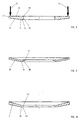
- Fig. 8 shows a section through another sealing ring 7.
- This has a flat surface 33 on it one side and one from a narrow flat surface 34 and one adjoining at an obtuse angle conical surface 35 existing surface on the other side. So on this page an apex 36 is formed, which in operation the one forms annular sealing surface while the other ring-shaped sealing surface through the inner edge 37 of the surface 33 on the opposite side of the sealing ring 7 is formed.
- the tapering of the ring 7 enables pressing down of the tapered edge of the ring 7 to in the plane of the surface of the non-tapered part uniform ring thickness if the ring 7 on a flat surface of a machine part, which extends far beyond the ring.
- Fig. 9 shows a section through a truncated cone Sealing ring as a stamped and pressed part is made of sheet metal.
- a narrow inner conical part 38 meets in the apex 36 with an outer wider conical part 39 together.
- the crown 36 forms a ring-shaped sealing surface, while the other ring-shaped sealing surface through the Inner edge 37 of the sealing ring 7 on the opposite Side of the sealing ring 7 is formed.
- FIG. 10 shows a section through a plane Middle section 40 and a conical, itself in its Outer ring region 41 which widens material thickness designed sealing ring 7.
- the apex also forms here 36 a ring-shaped sealing surface, while the other ring-shaped sealing surface through the inner edge 42 of the sealing ring 7 on the opposite Side of the sealing ring 7 is formed.
- FIG. 11 shows one clamped on the outside by means of a clamp 43 Ring 7 in the area between the sealing surface 44 and the clamp 43 is applied with force is.
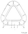
- the application of force on one side via the sealing surface protruding part of the ring can also become undesirable Lead tension in the ring. Leave this through slots in the one-sided over the sealing surface protruding part of the ring, its direction preferably runs radially away from the sealing surface.
- the Fig.12 shows a triangular ring with such Slits. With such a ring, the straight line and curved surfaces and that in the unstressed or unloaded condition, the unwanted occur Stresses and deformations preferably in the curved surfaces and in the transitions from curved surfaces in straight surfaces.
- the Force is applied to such slotted rings to be done on each surface between two slots.
Landscapes
- Engineering & Computer Science (AREA)
- Mechanical Engineering (AREA)
- Extrusion Moulding Of Plastics Or The Like (AREA)
- Sealing Devices (AREA)
Applications Claiming Priority (2)
| Application Number | Priority Date | Filing Date | Title |
|---|---|---|---|
| DE19702806 | 1997-01-27 | ||
| DE19702806A DE19702806C1 (de) | 1997-01-27 | 1997-01-27 | Verfahren und Vorrichtung zum Abdichten eines Ringspaltes zwischen zwei Dichtflächen von Maschinenteilen, insbesondere an Extrusionsmaschinen |
Publications (3)
| Publication Number | Publication Date |
|---|---|
| EP0855262A2 true EP0855262A2 (fr) | 1998-07-29 |
| EP0855262A3 EP0855262A3 (fr) | 2000-05-17 |
| EP0855262B1 EP0855262B1 (fr) | 2003-06-04 |
Family
ID=7818443
Family Applications (1)
| Application Number | Title | Priority Date | Filing Date |
|---|---|---|---|
| EP98100656A Expired - Lifetime EP0855262B1 (fr) | 1997-01-27 | 1998-01-16 | Procédé et appareil d'étanchéification pour l'interstice annuliare entre deux surfaces d'étanchéité annulaires, notamment pour de machines à extruder |
Country Status (6)
| Country | Link |
|---|---|
| US (1) | US6260852B1 (fr) |
| EP (1) | EP0855262B1 (fr) |
| JP (1) | JPH10211645A (fr) |
| CZ (1) | CZ24098A3 (fr) |
| DE (2) | DE19702806C1 (fr) |
| ES (1) | ES2201343T3 (fr) |
Cited By (1)
| Publication number | Priority date | Publication date | Assignee | Title |
|---|---|---|---|---|
| EP1174244A1 (fr) * | 2000-07-16 | 2002-01-23 | Paul Troester Maschinenfabrik | Dispositif d'étanchéité pour plaque à orifices dans une extrudeuse |
Families Citing this family (8)
| Publication number | Priority date | Publication date | Assignee | Title |
|---|---|---|---|---|
| US6517076B1 (en) * | 2000-04-06 | 2003-02-11 | Saint-Gobain Performance Plastics Corporation | Sealing method, new seal for components of fluid transfer systems, especially tubes, and their applications, especially in pumps and circuits for special fluids |
| DE10103005A1 (de) * | 2000-07-16 | 2002-01-24 | Troester Maschf Paul | Vorrichtung zur Abdichtung einer Lochscheibe in einer Extrusionsanlage |
| US7147774B2 (en) * | 2003-04-10 | 2006-12-12 | Polymer Systems, Inc. | Sliding plate filter with segmented sealing ring |
| EP1481786A1 (fr) * | 2003-05-28 | 2004-12-01 | Coperion Werner & Pfleiderer GmbH & Co. KG | Dispositif de traitement des matières liquides |
| DE102010043786B4 (de) * | 2010-11-11 | 2013-07-18 | Ralph Peter Hegler | Vorrichtung zur Herstellung von Rohren aus thermoplastischem Kunststoff |
| EP3308940B1 (fr) * | 2016-10-17 | 2025-03-05 | Next Generation Analytics GmbH | Système de filtre pour les fluides visqueux ou fortement visqueux, surtout plastique fondu et procédé de filtration des liquides visqueux ou fortement visqueux |
| JP7051363B2 (ja) * | 2017-10-17 | 2022-04-11 | 株式会社タハラ | スクリーンチェンジャとそれを用いた押出機および中空成形機 |
| US11260570B2 (en) * | 2018-05-07 | 2022-03-01 | PSI-Polymer Systems, Inc. | Filtration apparatuses and screen changer devices for polymer processing and related methods |
Family Cites Families (23)
| Publication number | Priority date | Publication date | Assignee | Title |
|---|---|---|---|---|
| US2998288A (en) * | 1959-12-30 | 1961-08-29 | Clark Equipment Co | Piston |
| US3583453A (en) * | 1968-03-13 | 1971-06-08 | Messrs Windmoller & Holscher | Screen-changing apparatus for extruders |
| US3587155A (en) * | 1968-09-06 | 1971-06-28 | Int Harvester Co | Ring manufacture,productive of line contact seal |
| DE1919269B1 (de) * | 1969-04-16 | 1970-07-23 | Hermann Berstorff Maschb Gmbh | Siebwechseleinrichtung fuer einen Extruder |
| US3675934A (en) * | 1970-06-01 | 1972-07-11 | Eugene E Heston | Screen changer mounting |
| US3724064A (en) * | 1970-07-02 | 1973-04-03 | Mott Metallurg Corp | Sealing method |
| US3684419A (en) * | 1971-01-25 | 1972-08-15 | Bradford R Voight | Screen changer for extruders |
| IT1017448B (it) * | 1973-08-02 | 1977-07-20 | Scheer & Cie C F | Dsipositivo per la filtrazione di materia plstica fusa nonche per l estrusione di cordoni di materia plastica |
| US3856277A (en) * | 1973-09-28 | 1974-12-24 | Gloucester Eng Co Inc | Screen assembly for processing plastic |
| US3962092A (en) * | 1975-01-10 | 1976-06-08 | The Dow Chemical Company | Screen changer |
| US3983038A (en) * | 1975-11-03 | 1976-09-28 | Heston Eugene E | Self-purging screen changer and strainer plate |
| US4053166A (en) * | 1975-12-08 | 1977-10-11 | Halogen Insulator & Seal Corporation | Two-piece seal |
| US4289319A (en) * | 1978-08-22 | 1981-09-15 | Usm Corporation | Rotary seal construction and processor |
| DE2836847A1 (de) * | 1978-08-23 | 1980-03-06 | Bayer Ag | Volumenarme mehrwellenschneckenmaschinenaustrittsvorrichtung mit siebwechselvorrichtung |
| US4268237A (en) * | 1980-03-26 | 1981-05-19 | Hawo B.V. | Apparatus for manufacturing a tubular body provided with a sealing ring |
| DE3017337A1 (de) * | 1980-05-06 | 1981-11-12 | Windmöller & Hölscher, 4540 Lengerich | Vorrichtung zum wechseln von siebsaetzen im auslaufbereich von extruder-strangpressen |
| DE3043217C2 (de) * | 1980-11-15 | 1982-07-15 | Hermann Berstorff Maschinenbau Gmbh, 3000 Hannover | Sieb- oder Werkzeugwechselvorrichtung für Schneckenextruder |
| US4410189A (en) * | 1982-05-13 | 1983-10-18 | The United States Of America As Represented By The Administrator Of The National Aeronautics And Space Administration | Resilient seal ring assembly with spring means applying force to wedge member |
| SU1388308A1 (ru) * | 1986-09-15 | 1988-04-15 | Украинский Научно-Исследовательский И Конструкторский Институт По Разработке Машин И Оборудования Для Переработки Пластических Масс,Резины И Искусственной Кожи | Экструдер дл переработки и фильтрации пластмассы |
| DE4227137C2 (de) * | 1991-02-25 | 1995-04-27 | Rielmann Hans Georg | Filtereinrichtung für flüssigen Kunststoff führende Druckleitungen |
| US5246236A (en) * | 1992-01-21 | 1993-09-21 | Halliburton Company | Seal for long-time exposures in oil and gas well tools |
| US5439589A (en) * | 1994-05-09 | 1995-08-08 | Trafalgar House Inc. | Sealing means for slide plate screen changer |
| JP2855088B2 (ja) * | 1995-04-19 | 1999-02-10 | 株式会社日本製鋼所 | スクリーンチェンジャの瀘過方法及びスクリーンチェンジャ |
-
1997
- 1997-01-27 DE DE19702806A patent/DE19702806C1/de not_active Expired - Fee Related
-
1998
- 1998-01-16 EP EP98100656A patent/EP0855262B1/fr not_active Expired - Lifetime
- 1998-01-16 ES ES98100656T patent/ES2201343T3/es not_active Expired - Lifetime
- 1998-01-16 DE DE59808552T patent/DE59808552D1/de not_active Expired - Fee Related
- 1998-01-26 US US09/013,525 patent/US6260852B1/en not_active Expired - Fee Related
- 1998-01-26 JP JP10013030A patent/JPH10211645A/ja active Pending
- 1998-01-27 CZ CZ98240A patent/CZ24098A3/cs unknown
Cited By (1)
| Publication number | Priority date | Publication date | Assignee | Title |
|---|---|---|---|---|
| EP1174244A1 (fr) * | 2000-07-16 | 2002-01-23 | Paul Troester Maschinenfabrik | Dispositif d'étanchéité pour plaque à orifices dans une extrudeuse |
Also Published As
| Publication number | Publication date |
|---|---|
| EP0855262B1 (fr) | 2003-06-04 |
| US6260852B1 (en) | 2001-07-17 |
| EP0855262A3 (fr) | 2000-05-17 |
| ES2201343T3 (es) | 2004-03-16 |
| CZ24098A3 (cs) | 1998-08-12 |
| JPH10211645A (ja) | 1998-08-11 |
| DE19702806C1 (de) | 1998-08-06 |
| DE59808552D1 (de) | 2003-07-10 |
Similar Documents
| Publication | Publication Date | Title |
|---|---|---|
| DE2000921C2 (de) | Dichtungsanordnung für Rohrverbindungen | |
| EP0221355B1 (fr) | Dispositif et procédé de nettoyage de matériaux visqueux | |
| EP3390881B1 (fr) | Conduite tubulaire et raccord tubulaire | |
| CH668629A5 (de) | Rohrverschraubung mit beruehrungsdichtung. | |
| DE4446506A1 (de) | Vorrichtung zum Aufweiten von Hohlkörpern | |
| EP0855262B1 (fr) | Procédé et appareil d'étanchéification pour l'interstice annuliare entre deux surfaces d'étanchéité annulaires, notamment pour de machines à extruder | |
| DE102009058361B3 (de) | Düse | |
| EP1097332A1 (fr) | Paroi de canal d'ecoulement | |
| AT514439B1 (de) | Filtervorrichtung | |
| EP0412997B1 (fr) | Garniture d'etancheite | |
| DE69017216T2 (de) | Drehbares wechselventil mit flachen absperrschiebern. | |
| DE3242286C2 (de) | Siebwechselvorrichtung für Extruder mit hohen Betriebsdrücken | |
| DE2856097A1 (de) | Schneckenstrangpresse fuer die verarbeitung von kunststoff, kautschuk o.dgl. | |
| DE4133763C2 (de) | Dichteinrichtung | |
| WO2002098628A2 (fr) | Bague de serrage pour le raccordement axial de pieces cylindriques | |
| DE2848274C2 (de) | Kammerwerkzeug für Strangpressen, insbesondere für Aluminium-Profile | |
| DE1602521C3 (de) | Vorrichtung zum Tiefziehen von insbesondere zylindrischen Hohlkörpern | |
| DE2420483C2 (de) | Dichtung für bewegliche Teile, insbesondere Teile von Verteilungsschiebern | |
| EP0153560A2 (fr) | Dispositif de serrage | |
| DE10356269B3 (de) | Vorrichtung zur Abdichtung des Spaltes zwischen sich relativ zueinander bewegenden Werkzeugteilen gegen das Eindringen von flüssigen oder teilflüssigen metallischen Werkstoffen in diesen Spalt | |
| AT208577B (de) | Matrize zum Strangpressen von thermoplastischen Harzen od. dgl. | |
| DE909334C (de) | Pressenkopf fuer Strangpressen, insbesondere fuer Kabelmantelpressen | |
| EP0999361B1 (fr) | Dispositif avec jonction de perçages | |
| EP2085675A1 (fr) | Dispositif de raccord | |
| DE1602282C3 (de) | Quergeteilte Matrize für das Kaltfließpressen von Rohlingen |
Legal Events
| Date | Code | Title | Description |
|---|---|---|---|
| PUAI | Public reference made under article 153(3) epc to a published international application that has entered the european phase |
Free format text: ORIGINAL CODE: 0009012 |
|
| AK | Designated contracting states |
Kind code of ref document: A2 Designated state(s): CH DE ES FR GB IT LI |
|
| AX | Request for extension of the european patent |
Free format text: AL;LT;LV;MK;RO;SI |
|
| PUAL | Search report despatched |
Free format text: ORIGINAL CODE: 0009013 |
|
| RIC1 | Information provided on ipc code assigned before grant |
Free format text: 7B 29C 47/08 A, 7B 29C 47/68 B |
|
| AK | Designated contracting states |
Kind code of ref document: A3 Designated state(s): AT BE CH DE DK ES FI FR GB GR IE IT LI LU MC NL PT SE |
|
| AX | Request for extension of the european patent |
Free format text: AL;LT;LV;MK;RO;SI |
|
| 17P | Request for examination filed |
Effective date: 20000524 |
|
| AKX | Designation fees paid |
Free format text: CH DE ES FR GB IT LI |
|
| 17Q | First examination report despatched |
Effective date: 20010403 |
|
| GRAH | Despatch of communication of intention to grant a patent |
Free format text: ORIGINAL CODE: EPIDOS IGRA |
|
| GRAH | Despatch of communication of intention to grant a patent |
Free format text: ORIGINAL CODE: EPIDOS IGRA |
|
| GRAA | (expected) grant |
Free format text: ORIGINAL CODE: 0009210 |
|
| AK | Designated contracting states |
Designated state(s): CH DE ES FR GB IT LI |
|
| PG25 | Lapsed in a contracting state [announced via postgrant information from national office to epo] |
Ref country code: GB Free format text: LAPSE BECAUSE OF FAILURE TO SUBMIT A TRANSLATION OF THE DESCRIPTION OR TO PAY THE FEE WITHIN THE PRESCRIBED TIME-LIMIT Effective date: 20030604 Ref country code: FR Free format text: LAPSE BECAUSE OF FAILURE TO SUBMIT A TRANSLATION OF THE DESCRIPTION OR TO PAY THE FEE WITHIN THE PRESCRIBED TIME-LIMIT Effective date: 20030604 |
|
| REG | Reference to a national code |
Ref country code: GB Ref legal event code: FG4D Free format text: NOT ENGLISH |
|
| REG | Reference to a national code |
Ref country code: CH Ref legal event code: EP |
|
| REF | Corresponds to: |
Ref document number: 59808552 Country of ref document: DE Date of ref document: 20030710 Kind code of ref document: P |
|
| GBV | Gb: ep patent (uk) treated as always having been void in accordance with gb section 77(7)/1977 [no translation filed] |
Effective date: 20030604 |
|
| PGFP | Annual fee paid to national office [announced via postgrant information from national office to epo] |
Ref country code: ES Payment date: 20031230 Year of fee payment: 7 |
|
| PGFP | Annual fee paid to national office [announced via postgrant information from national office to epo] |
Ref country code: DE Payment date: 20040114 Year of fee payment: 7 |
|
| PG25 | Lapsed in a contracting state [announced via postgrant information from national office to epo] |
Ref country code: LI Free format text: LAPSE BECAUSE OF NON-PAYMENT OF DUE FEES Effective date: 20040131 Ref country code: CH Free format text: LAPSE BECAUSE OF NON-PAYMENT OF DUE FEES Effective date: 20040131 |
|
| REG | Reference to a national code |
Ref country code: ES Ref legal event code: FG2A Ref document number: 2201343 Country of ref document: ES Kind code of ref document: T3 |
|
| PLBE | No opposition filed within time limit |
Free format text: ORIGINAL CODE: 0009261 |
|
| STAA | Information on the status of an ep patent application or granted ep patent |
Free format text: STATUS: NO OPPOSITION FILED WITHIN TIME LIMIT |
|
| 26N | No opposition filed |
Effective date: 20040305 |
|
| EN | Fr: translation not filed | ||
| REG | Reference to a national code |
Ref country code: CH Ref legal event code: PL |
|
| PG25 | Lapsed in a contracting state [announced via postgrant information from national office to epo] |
Ref country code: IT Free format text: LAPSE BECAUSE OF NON-PAYMENT OF DUE FEES Effective date: 20050116 |
|
| PG25 | Lapsed in a contracting state [announced via postgrant information from national office to epo] |
Ref country code: ES Free format text: LAPSE BECAUSE OF NON-PAYMENT OF DUE FEES Effective date: 20050117 |
|
| PG25 | Lapsed in a contracting state [announced via postgrant information from national office to epo] |
Ref country code: DE Free format text: LAPSE BECAUSE OF NON-PAYMENT OF DUE FEES Effective date: 20050802 |
|
| REG | Reference to a national code |
Ref country code: ES Ref legal event code: FD2A Effective date: 20050117 |