EP0855294A2 - Appareil pour régler la pression dans les pneumatiques de véhicules automobiles - Google Patents
Appareil pour régler la pression dans les pneumatiques de véhicules automobiles Download PDFInfo
- Publication number
- EP0855294A2 EP0855294A2 EP98810026A EP98810026A EP0855294A2 EP 0855294 A2 EP0855294 A2 EP 0855294A2 EP 98810026 A EP98810026 A EP 98810026A EP 98810026 A EP98810026 A EP 98810026A EP 0855294 A2 EP0855294 A2 EP 0855294A2
- Authority
- EP
- European Patent Office
- Prior art keywords
- vehicle wheel
- tire
- mass
- piston pump
- interior
- Prior art date
- Legal status (The legal status is an assumption and is not a legal conclusion. Google has not performed a legal analysis and makes no representation as to the accuracy of the status listed.)
- Withdrawn
Links
- 239000003570 air Substances 0.000 claims description 15
- 239000012080 ambient air Substances 0.000 claims description 11
- 230000001105 regulatory effect Effects 0.000 claims description 7
- 230000005484 gravity Effects 0.000 claims 2
- 230000001133 acceleration Effects 0.000 claims 1
- 238000005096 rolling process Methods 0.000 claims 1
- 238000005086 pumping Methods 0.000 description 5
- 230000002411 adverse Effects 0.000 description 1
- 230000000694 effects Effects 0.000 description 1
- 230000003068 static effect Effects 0.000 description 1
Images


Classifications
-
- B—PERFORMING OPERATIONS; TRANSPORTING
- B60—VEHICLES IN GENERAL
- B60C—VEHICLE TYRES; TYRE INFLATION; TYRE CHANGING; CONNECTING VALVES TO INFLATABLE ELASTIC BODIES IN GENERAL; DEVICES OR ARRANGEMENTS RELATED TO TYRES
- B60C23/00—Devices for measuring, signalling, controlling, or distributing tyre pressure or temperature, specially adapted for mounting on vehicles; Arrangement of tyre inflating devices on vehicles, e.g. of pumps or of tanks; Tyre cooling arrangements
- B60C23/10—Arrangement of tyre-inflating pumps mounted on vehicles
- B60C23/12—Arrangement of tyre-inflating pumps mounted on vehicles operated by a running wheel
- B60C23/133—Arrangement of tyre-inflating pumps mounted on vehicles operated by a running wheel activated by centrifugal force
Definitions
- the invention enters a device for regulating or keeping the Air pressure in the interior of a tire on a vehicle wheel, acting as a stand-alone Device is limited to the respective vehicle wheel, according to the Preamble of claim 1.
- WO 95/19271 is an automatic independent and not with Body-connected piston pump known for inflating a vehicle tire, which is mounted on the rim of the vehicle wheel and a piston in one Has cylinder which is held in a defined rest position by a spring is, the mass of the piston reacts to forces, either during rotation the rim as centrifugal force at higher speeds or when driving over Road bumps are generated as mass forces.
- the mass of the piston reacts to forces, either during rotation the rim as centrifugal force at higher speeds or when driving over Road bumps are generated as mass forces.
- For vehicles that are high Rims must reach speeds together with the tires be balanced together; the deviations from the ideal zero balancing have to be within narrow limits.
- the radial deflection alone of the piston against the spring changes the balance of the wheel in such a way that there is intolerable vibration of the vehicle at high speeds is coming.
- Static balancing aids are provided that support the rim with the tire at rest, possibly for low speeds help satisfactorily balance.
- the EM 600 037 B1 is also on the rim of a vehicle wheel mounted piston pump become known, which is off-center and tangential to Path of the wheel rotation placed in the line of the reciprocation of the piston is.
- the piston is freely movable and reacts to the gravitational forces at rotation and vibrations caused by driving over uneven ground occur on the rim.
- the rim is through the arrangement of the piston pump as in the arrangement of the piston pump mentioned under WO 95/19 271 unilaterally loaded with weights that have to be balanced, under dynamic conditions due to the freedom of movement of the piston exact balancing is still not possible.
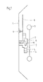
- the facility itself comprises a piston pump 2 with a pump housing, in which at least a cylinder 4 is arranged, in which a piston 5 can be moved back and forth.
- the pistons are connected to a mass 7 via a crankshaft 6, the Mass 7 is a flywheel, which rotates with respect to the pump housing 2 causes the piston 5 to reciprocate.
- the piston pump 2 sucks in ambient air through the reciprocating movements of the pistons 5, compressed this, and passes them via a pressure line 8 into the interior of the tire further, provided the piston pump has the appropriate Valves, which usually flow through from a first cylinder Check valve 29 a for sucking in ambient air and from a second one Check valve 29b is there, which compressed air from the inside of the cylinder 4 can pass through the pressure line 8 to the tire, as it is in the detail drawing 3 is shown.
- the pressure relief valve 9 With the help of the pressure relief valve 9 the air pressure in the tire limits, but the activity of the piston pump 2 none Stopped. For certain applications it is recommended to use the pressure relief valve 9 adjustable, because different vehicle loads and / or different road conditions different air pressure conditions are required in the tire.
- the operation of the piston pump 2 depends on the movement of the vehicle and thus the speed or the speed change of the vehicle wheel. If the vehicle accelerates, the mass 7 remains in the form of the flywheel back, so it rotates more slowly than the piston pump 2 with its pump housing 3, which rotates at the speed of the vehicle wheel, causing the crankshaft the pistons 5 with the differential speed occurring between the vehicle wheel and drives the flywheel. Ambient air is sucked in, compressed and transported into the inside of the tire via the pressure line 8. Is the the pressure occurring here is greater than that limited by the pressure relief valve 9 Internal pressure of the tire, so the ambient air compressed by the piston pump 2 Pumped outdoors without detours.
- the arrangement of the facility is in the rim housing 1 is arranged rotationally symmetrical, and thus has the Balance condition of the vehicle wheel has no influence.
- the device 2 is a device for regulating or keeping the air pressure constant described in the interior of a tire on a vehicle wheel, the also limited to the respective vehicle wheel as an independent device and is arranged on a rim housing 11 which is on the vehicle wheel, Similar to a hubcap, concentrically around the central axis M of the vehicle wheel this is attached.
- the device is therefore not visible from outside and should be connectable to commercially available vehicle wheels in this way.
- the device itself comprises a piston pump 12 with a pump housing 13, in which at least one cylinder 14 is arranged, in which at least one Piston 15 is movable back and forth.
- the operation of the piston pump depends on the movement of the vehicle wheel, which arises in that the vehicle wheel over bumps of the Roadway rolls.
- the resulting vertical movements of the vehicle wheel the inertial mass 17 cannot follow and generates relative movements via the pistons 15 to the cylinders vibrating together with the vehicle wheel 14, which are used for pumping movements. If the mass 17 away from the central axis M, it is subject to the centrifugal force due to the rotation of the vehicle wheel, which is compensated by the diaphragm spring 16 ', however the oscillating movements of the mass essentially around the central one Move center axis M. Ambient air is sucked in through the pumping movements, compressed and transported into the interior of the tire above you pressure line 18.
- the device comprises a piston pump 22 with a pump housing 23, in which at least one cylinder 24 is arranged, in which a Piston 25 is movable back and forth.
- Each of the pistons 25 has a mass 27 on, which is supported via a return spring 26 'against the pump housing 23.
- each cylinder 24 with its piston 25 represents a piston pump 22, which is brought together in a pressure line 28 that communicates with the interior of the tire.
- the pressure line 28 has a pressure relief valve 29, which can be adjustable and for this ensures that the tire's internal pressure maintains a constant air pressure at all times having.
- the operation of the piston pump 2 depends on the movement of the vehicle, and thus of the speed or speed change of the Vehicle wheel in such a way that the masses 27 both the centrifugal forces and are exposed to the mass forces caused by uneven ground.
Landscapes
- Engineering & Computer Science (AREA)
- Mechanical Engineering (AREA)
- Tires In General (AREA)
- Compressors, Vaccum Pumps And Other Relevant Systems (AREA)
- Testing Of Balance (AREA)
Applications Claiming Priority (2)
| Application Number | Priority Date | Filing Date | Title |
|---|---|---|---|
| DE19702055A DE19702055A1 (de) | 1997-01-22 | 1997-01-22 | Einrichtung zur Regelung des Innendruckes bei Kraftfahrzeugreifen |
| DE19702055 | 1997-01-22 |
Publications (2)
| Publication Number | Publication Date |
|---|---|
| EP0855294A2 true EP0855294A2 (fr) | 1998-07-29 |
| EP0855294A3 EP0855294A3 (fr) | 1999-12-08 |
Family
ID=7817972
Family Applications (1)
| Application Number | Title | Priority Date | Filing Date |
|---|---|---|---|
| EP98810026A Withdrawn EP0855294A3 (fr) | 1997-01-22 | 1998-01-21 | Appareil pour régler la pression dans les pneumatiques de véhicules automobiles |
Country Status (2)
| Country | Link |
|---|---|
| EP (1) | EP0855294A3 (fr) |
| DE (1) | DE19702055A1 (fr) |
Cited By (6)
| Publication number | Priority date | Publication date | Assignee | Title |
|---|---|---|---|---|
| WO2013037052A1 (fr) * | 2011-09-15 | 2013-03-21 | Magna International Inc. | Système de gonflage de pneu automatique |
| US20170015156A1 (en) * | 2015-07-14 | 2017-01-19 | Intelliaire, Llc | System and method for gravity-driven automatic tire pumps |
| US9809066B2 (en) | 2014-05-05 | 2017-11-07 | The Goodyear Tire & Rubber Company | System for an air maintenance tire assembly |
| US10105999B2 (en) | 2015-07-14 | 2018-10-23 | Intelliaire, Llc | System and method for tire rims configured to receive gravity-based devices |
| US10759236B2 (en) | 2017-05-04 | 2020-09-01 | The Goodyear Tire & Rubber Company | Wheel for an air maintenance tire system |
| EP4281281B1 (fr) | 2021-01-25 | 2025-01-15 | KT Projektentwicklungs-GmbH | Kit de réparation de pneumatique et méthode de gonflage et/ou de scellage d'un pneumatique |
Families Citing this family (1)
| Publication number | Priority date | Publication date | Assignee | Title |
|---|---|---|---|---|
| DE102022002574A1 (de) | 2022-07-14 | 2024-01-25 | Abdullatif Alhaj Rabie | Radkappe-Luftpumpe |
Citations (2)
| Publication number | Priority date | Publication date | Assignee | Title |
|---|---|---|---|---|
| WO1995019271A1 (fr) | 1994-01-14 | 1995-07-20 | Vertigo, Inc. | Dispositif de gonflage de pneu, monte sur roue |
| EP0600037B1 (fr) | 1991-08-27 | 1996-05-22 | Cycloid Company | Appareil de gonflage sous pression d'un pneu et de regulation de la pression |
Family Cites Families (5)
| Publication number | Priority date | Publication date | Assignee | Title |
|---|---|---|---|---|
| US1887715A (en) * | 1931-04-03 | 1932-11-15 | Edgar A Hester | Automobile tire pump |
| US2055983A (en) * | 1935-01-23 | 1936-09-29 | Houde Eng Corp | Automatic tire inflation attachment |
| DE724479C (de) * | 1940-10-10 | 1942-08-27 | Bayerische Motoren Werke Ag | Einrichtung zum selbsttaetigen AEndern des Reifendruckes |
| DE29506368U1 (de) * | 1995-04-13 | 1995-09-21 | Anson, Enrico, 58285 Gevelsberg | Gerät zur Erhaltung des erforderlichen Luftdruckes an Fahrzeugreifen |
| US5591281A (en) * | 1995-08-09 | 1997-01-07 | Loewe; Richard T. | Flywheel tire inflation device |
-
1997
- 1997-01-22 DE DE19702055A patent/DE19702055A1/de not_active Withdrawn
-
1998
- 1998-01-21 EP EP98810026A patent/EP0855294A3/fr not_active Withdrawn
Patent Citations (2)
| Publication number | Priority date | Publication date | Assignee | Title |
|---|---|---|---|---|
| EP0600037B1 (fr) | 1991-08-27 | 1996-05-22 | Cycloid Company | Appareil de gonflage sous pression d'un pneu et de regulation de la pression |
| WO1995019271A1 (fr) | 1994-01-14 | 1995-07-20 | Vertigo, Inc. | Dispositif de gonflage de pneu, monte sur roue |
Cited By (11)
| Publication number | Priority date | Publication date | Assignee | Title |
|---|---|---|---|---|
| WO2013037052A1 (fr) * | 2011-09-15 | 2013-03-21 | Magna International Inc. | Système de gonflage de pneu automatique |
| CN104024007A (zh) * | 2011-09-15 | 2014-09-03 | 麦格纳国际公司 | 自动轮胎充气系统 |
| US9809066B2 (en) | 2014-05-05 | 2017-11-07 | The Goodyear Tire & Rubber Company | System for an air maintenance tire assembly |
| US10773560B2 (en) | 2014-05-05 | 2020-09-15 | The Goodyear Tire & Rubber Company | System for an air maintenance tire assembly |
| US20170015156A1 (en) * | 2015-07-14 | 2017-01-19 | Intelliaire, Llc | System and method for gravity-driven automatic tire pumps |
| WO2017011692A1 (fr) * | 2015-07-14 | 2017-01-19 | Intelliaire, Llc | Système et procédé pour pompes de pneu automatique entraînées par la gravité |
| US10105999B2 (en) | 2015-07-14 | 2018-10-23 | Intelliaire, Llc | System and method for tire rims configured to receive gravity-based devices |
| US10137745B2 (en) | 2015-07-14 | 2018-11-27 | Intelliaire, Llc | System and method for maintaining target pressure in conjunction with gravity-driven automatic tire pumping mechanisms |
| US10358005B2 (en) * | 2015-07-14 | 2019-07-23 | Intelliaire, Llc | System and method for gravity-driven automatic tire pumps |
| US10759236B2 (en) | 2017-05-04 | 2020-09-01 | The Goodyear Tire & Rubber Company | Wheel for an air maintenance tire system |
| EP4281281B1 (fr) | 2021-01-25 | 2025-01-15 | KT Projektentwicklungs-GmbH | Kit de réparation de pneumatique et méthode de gonflage et/ou de scellage d'un pneumatique |
Also Published As
| Publication number | Publication date |
|---|---|
| EP0855294A3 (fr) | 1999-12-08 |
| DE19702055A1 (de) | 1998-07-23 |
Similar Documents
| Publication | Publication Date | Title |
|---|---|---|
| DE2831179C2 (fr) | ||
| DE60211892T2 (de) | Vorrichtung zum aufpumpen von fahrzeugreifen | |
| EP0208122A1 (fr) | Palier aérostatique en forme de double cône | |
| EP0855294A2 (fr) | Appareil pour régler la pression dans les pneumatiques de véhicules automobiles | |
| CH624451A5 (en) | Piston engine with means for the balancing of inertia forces | |
| DE805230C (de) | Motorfahrzeug, insbesondere Automobil mit mindestens drei Raedern | |
| DE19547043C2 (de) | Schwingungserreger zum Erzeugen einer gerichteten Schwingung | |
| DE19963831B4 (de) | Exzentertellerschleifer mit einem Gehäuse | |
| DD297512A5 (de) | Vorrichtung zur einstellung der geometrie eines fahrzeugrades | |
| DE3635769C2 (fr) | ||
| US3690398A (en) | Hydrostatic drive | |
| DE60107916T2 (de) | Vorrichtung zur dämpfung von drehbewegungen einer pendelradaufhängung eines kraftfahrzeuges | |
| DE926308C (de) | Walze zur Verdichtung von Bodenmassen, Schuettguetern od. dgl., insbesondere fuer den Strassenbau | |
| DE1125293B (de) | Ausgleichsfederung mit Stabilisierung fuer Fahrzeuge, insbesondere Kraftfahrzeuge | |
| DE2616192A1 (de) | Exzenter-hydraulikpumpe | |
| DE2147213A1 (de) | Anordnung zum vermindern der bei kolbenmaschinen verursachten vibrationen | |
| DE3244965A1 (de) | Vorrichtung zum schleifen der oberflaechen von insbesondere zylindrischen gegenstaenden | |
| DE9317640U1 (de) | Einrichtung zur Walzenschüttelung | |
| DE899913C (de) | Schleifeinrichtung, insbesondere fuer Feinziehschleifmaschinen | |
| EP1700034A1 (fr) | Machine a pistons axiaux pour realiser un acheminement independant dans plusieurs circuits hydrauliques | |
| CH659720A5 (de) | Vorrichtung zur veraenderung der vibrationskraft. | |
| DE19825923C1 (de) | Rollenprüfstand für Kraftfahrzeuge | |
| DD254079A1 (de) | Einrichtung zur einstellbaren, im wesentlichen horizontalen aufstellung eines geraetes | |
| DE364131C (de) | Federnde Nabe | |
| DD262601A1 (de) | Verstellbare unwucht |
Legal Events
| Date | Code | Title | Description |
|---|---|---|---|
| PUAI | Public reference made under article 153(3) epc to a published international application that has entered the european phase |
Free format text: ORIGINAL CODE: 0009012 |
|
| AK | Designated contracting states |
Kind code of ref document: A2 Designated state(s): DE FR GB IT |
|
| AX | Request for extension of the european patent |
Free format text: AL;LT;LV;MK;RO;SI |
|
| 17P | Request for examination filed |
Effective date: 19990120 |
|
| PUAL | Search report despatched |
Free format text: ORIGINAL CODE: 0009013 |
|
| AK | Designated contracting states |
Kind code of ref document: A3 Designated state(s): AT BE CH DE DK ES FI FR GB GR IE IT LI LU MC NL PT SE |
|
| AX | Request for extension of the european patent |
Free format text: AL;LT;LV;MK;RO;SI |
|
| AKX | Designation fees paid |
Free format text: DE FR GB IT |
|
| 17Q | First examination report despatched |
Effective date: 20020314 |
|
| RAP1 | Party data changed (applicant data changed or rights of an application transferred) |
Owner name: CONTINENTAL AKTIENGESELLSCHAFT |
|
| RIN1 | Information on inventor provided before grant (corrected) |
Inventor name: WYCHNANEK, RAINER Inventor name: WULFF, GUNTER, DR. |
|
| GRAP | Despatch of communication of intention to grant a patent |
Free format text: ORIGINAL CODE: EPIDOSNIGR1 |
|
| STAA | Information on the status of an ep patent application or granted ep patent |
Free format text: STATUS: THE APPLICATION IS DEEMED TO BE WITHDRAWN |
|
| 18D | Application deemed to be withdrawn |
Effective date: 20050412 |