EP0855306A2 - Übertragungskupplungseinheit - Google Patents
Übertragungskupplungseinheit Download PDFInfo
- Publication number
- EP0855306A2 EP0855306A2 EP98300465A EP98300465A EP0855306A2 EP 0855306 A2 EP0855306 A2 EP 0855306A2 EP 98300465 A EP98300465 A EP 98300465A EP 98300465 A EP98300465 A EP 98300465A EP 0855306 A2 EP0855306 A2 EP 0855306A2
- Authority
- EP
- European Patent Office
- Prior art keywords
- coupling
- shaft
- assembly
- splines
- coupling shaft
- Prior art date
- Legal status (The legal status is an assumption and is not a legal conclusion. Google has not performed a legal analysis and makes no representation as to the accuracy of the status listed.)
- Granted
Links
- 230000008878 coupling Effects 0.000 title claims abstract description 79
- 238000010168 coupling process Methods 0.000 title claims abstract description 79
- 238000005859 coupling reaction Methods 0.000 title claims abstract description 79
- 230000005540 biological transmission Effects 0.000 title claims abstract description 11
- 238000002485 combustion reaction Methods 0.000 claims abstract description 9
- 239000012530 fluid Substances 0.000 claims abstract description 4
- 239000000314 lubricant Substances 0.000 claims abstract description 4
- 238000006073 displacement reaction Methods 0.000 abstract description 5
- 238000005461 lubrication Methods 0.000 abstract description 2
- 230000007246 mechanism Effects 0.000 description 6
- 239000010720 hydraulic oil Substances 0.000 description 5
- JEIPFZHSYJVQDO-UHFFFAOYSA-N iron(III) oxide Inorganic materials O=[Fe]O[Fe]=O JEIPFZHSYJVQDO-UHFFFAOYSA-N 0.000 description 2
- 230000013011 mating Effects 0.000 description 2
- 238000000034 method Methods 0.000 description 2
- 230000002093 peripheral effect Effects 0.000 description 2
- 238000005452 bending Methods 0.000 description 1
- 238000010276 construction Methods 0.000 description 1
- 239000013536 elastomeric material Substances 0.000 description 1
- 238000004519 manufacturing process Methods 0.000 description 1
- 229920002994 synthetic fiber Polymers 0.000 description 1
Images

Classifications
-
- B—PERFORMING OPERATIONS; TRANSPORTING
- B60—VEHICLES IN GENERAL
- B60K—ARRANGEMENT OR MOUNTING OF PROPULSION UNITS OR OF TRANSMISSIONS IN VEHICLES; ARRANGEMENT OR MOUNTING OF PLURAL DIVERSE PRIME-MOVERS IN VEHICLES; AUXILIARY DRIVES FOR VEHICLES; INSTRUMENTATION OR DASHBOARDS FOR VEHICLES; ARRANGEMENTS IN CONNECTION WITH COOLING, AIR INTAKE, GAS EXHAUST OR FUEL SUPPLY OF PROPULSION UNITS IN VEHICLES
- B60K17/00—Arrangement or mounting of transmissions in vehicles
- B60K17/22—Arrangement or mounting of transmissions in vehicles characterised by arrangement, location, or type of main drive shafting, e.g. cardan shaft
Definitions
- the invention relates to a transmission coupling assembly for absorbing axial and/or angular displacement between an internal combustion engine and a downstream gear train.
- the invention is particularly suited for use in utility vehicles or agricultural tractors having resiliently mounted engines.
- the drive motor which is more often than not a diesel engine, may be resiliently mounted on a frame which is mounted by means of flanges on the gearbox housing.
- the drive motor and the gearbox housing are often spaced apart from one another to provide room for auxiliary drives (eg hydraulic pumps) which are mounted by means of flanges on the end face of the gearbox housing.
- Hydraulic pumps are required in say, a tractor, to supply hydraulic oil to the linkage lift mechanism and steering mechanism and for gear lubrication.
- the power is transmitted from the drive motor to the gearbox via an articulated shaft with longitudinal compensation, coupled with the engine output shaft and the gearbox input shaft by means of suitably sized flanges (see DE 38 34 919 A1). Because of the amount of space required for these flange mountings, the above-mentioned hydraulic pumps cannot be arranged as close to one another as their actual external dimensions would allow Larger pump drive gears are needed in the gearbox in order to bridge the distance, which in turn means having to increase the width of the gearbox housing in an undesirable manner.
- the semi-chassis frame also needs to be made wider and this is undesirable since it places a restriction on the size of the steering lock angle of the steered front wheels.
- the objective of the invention is to provide a transmission coupling assembly which will allow the hydraulic pumps to be arranged closer to the gear input shaft than has hitherto been possible in order to reduce the width dimensions of both the gearbox housing and the semi-chassis frame.
- the simplest and fastest embodiment in terms of assembling and dismantling the transmission coupling is distinctive in that the fixed rotary coupling between a coupling member on the output side of the vibration damper and the coupling shaft is provided by means of splines, the coupling member being provided with straight splines and a boss of the shaft with curved splines.
- the boss region of the coupling shaft may be mounted on the free, tapered end region of a spigot secured to the flywheel of the internal combustion engine which is received in a bearing region of the boss.
- the spigot is tapered or has a reduced diameter relative to the diameter of the bearing region over at least the length L.
- a boss joined to the shaft and rotationally fast therewith is bolted to the coupling member on the side facing the internal combustion engine.
- an end or bearing region of the coupling shaft on the internal combustion engine side is of a rounded design and, in the operating position, is received in a bearing bush joined to the flywheel and the part of the shaft between the boss and the rounded bearing region is of a minimum length L and is tapered or of reduced diameter relative to the diameter of the bearing region.
- lubricant fluid eg hydraulic oil is supplied to the coupling between the coupling shaft and gearbox input shaft.
- this region is closed off by means of a seal having a Z-shaped cross-section.
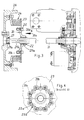
- Figure 1 illustrates only the flywheel 1 of the drive motor of a utility vehicle.
- a torsional vibration damper 3 mounted on the flywheel 1 by means of bolts 2 is a torsional vibration damper 3, the coupling member 4 on the output side of which has internal splines 4a. Meshing with the internal splines are external, spherically curved splines 5a of a boss 5, which is rotationally fast to a coupling shaft 7 by means of splines 5b.
- a bolt 6 is also used to prevent bending.
- the coupling shaft 7 has external crowned or curved splines 7a, also spherical, which mesh with internal splines 8a of the input shaft 3 of a gearbox 9 such that the depth to which it penetrates the input shaft 8 is determined by the distance L.
- the coupling shaft 7 is axially fixed in this position relative to the input shaft 8 by means of a supporting ring 10 and retaining ring 11.
- Mounted on the gearbox housing at a slight distance away from the point at which the shaft 7 penetrates the gearbox 9 are two pumps 12, 13 which deliver the requisite hydraulic oil for the on-board hydraulic consumers, such as the steering mechanism or - in the case of agricultural tractors - the linkage lift mechanism.
- the pumps 12, 13 are driven by the input shaft 8 via gears 14 and 15.
- the boss 5 is supported by means of a bearing ring 16 on a spigot 17 mounted on the flywheel 1.
- the spigot is of rounded section at the end lying in the bearing region, whilst the region 17a lying behind is of a tapered design, with cylindrical region 17b lying behind the tapered region and being smaller in diameter than the bearing region.
- the cylindrical region 17b, or the combination of the cylindrical region and the tapered region 17a, is of 7 length L1 > L. The space surrounding the cylindrical region 17b is kept free of any other components.
- the boss bore 5c receiving the bearing ring 16 also has an effective depth L1 > dimension L so that once the axial fixing is released, the coupling shaft 7 together with the boss 5 can be pushed towards the left in Figure 1 by at least the distance L out of the operating position illustrated in Figure 1. Since, in this case, the gearbox-side end of the coupling shaft 7 is removed completely from the input shaft 8 of the gearbox 9, the gearbox-side end region of the coupling shaft 7 can be swung away from the axis of the input shaft 8. The boss 5 is then removed by sliding the splines 5a through the splines 4a of the coupling member 4. This is possible because of the spherically curved or crowned profile of the splines 5a of the boss 5. The transmission coupling can thus be quickly and rapidly dismantled in this manner or - in the reverse process - assembled.
- the transmission coupling assembly provides two articulated points whereby any axial or angular displacements are tolerated and any vibrations of the drive motor eg due to its resilient mountings are absorbed without these being passed on to the gear mechanism.
- the transmission coupling assembly of Figure 3 differs from the one described above essentially only by dint of the design of the boss 20 and the bearing of the shaft 21 on the internal combustion engine side.
- the boss 20 is arranged on a larger diameter portion of the coupling shaft at a distance greater than the length L from the drive-side.
- the boss 20 is made rotationally and axially fast to the shaft by means of splines 20a and retaining rings 22.
- the boss 20 has a plurality of radial lugs 20b, which are separated from one another by intermediate spaces which are wider than the lugs.
- Arranged around a notional circle centred on the axis of the boss 20 are a number of threaded bores 20c, one in each lug 20b.
- the coupling member 23 of the torsional vibration damper 24 has in its inner peripheral region the same number of inwardly pointing lugs 23a each having a bore 23b, the bores 23b lying on the same notional circle as the threaded bores 20c.
- the width of the lugs 23a corresponds to that of the lugs 20b so that the relative position of the boss 20 to the coupling member 23 as illustrated in Figure 4 is such that the boss 20 can be passed through the coupling member 23 for assembling or dismantling the transmission coupling unhindered.
- boss 20 In the operating position illustrated in Figure 3, the boss 20 is centred against the coupling member 23 the boss having a shoulder 20d which engages the coupling member.
- the boss and coupling member are oriented in the direction of rotation such that the bores in the lugs 20b and in the lugs 23a align with one another. In this position, boss 20 and coupling 23 are joined to one another by means of bolts 25.
- the shaft 21 is centrally guided (a function which cannot be assumed by the torsional vibration damper 23 in this case either) by means of a bearing bush 27, in which the rounded section end region 21a of the shaft 21 is received, the diameter thereof being only slighted smaller than the boss seat.
- the shaft portion 21b between the boss and the end region 21a has a smaller diameter, which makes for simple assembly and dismantling of the shaft 21 since the end region can be slid further into the bearing bush 27 on assembly and disassembly.
Landscapes
- Engineering & Computer Science (AREA)
- Chemical & Material Sciences (AREA)
- Combustion & Propulsion (AREA)
- Transportation (AREA)
- Mechanical Engineering (AREA)
- Mechanical Operated Clutches (AREA)
- General Details Of Gearings (AREA)
- Arrangement Of Transmissions (AREA)
- Motor Power Transmission Devices (AREA)
- Massaging Devices (AREA)
- Gears, Cams (AREA)
- Sealing Devices (AREA)
Applications Claiming Priority (2)
| Application Number | Priority Date | Filing Date | Title |
|---|---|---|---|
| DE19702682 | 1997-01-25 | ||
| DE19702682A DE19702682A1 (de) | 1997-01-25 | 1997-01-25 | Achs- und/oder Winkelversatz ausgleichender Antriebsverbindung |
Publications (3)
| Publication Number | Publication Date |
|---|---|
| EP0855306A2 true EP0855306A2 (de) | 1998-07-29 |
| EP0855306A3 EP0855306A3 (de) | 2000-01-12 |
| EP0855306B1 EP0855306B1 (de) | 2004-03-03 |
Family
ID=7818357
Family Applications (1)
| Application Number | Title | Priority Date | Filing Date |
|---|---|---|---|
| EP98300465A Expired - Lifetime EP0855306B1 (de) | 1997-01-25 | 1998-01-23 | Übertragungskupplungseinheit |
Country Status (4)
| Country | Link |
|---|---|
| US (1) | US6117016A (de) |
| EP (1) | EP0855306B1 (de) |
| AT (1) | ATE260782T1 (de) |
| DE (2) | DE19702682A1 (de) |
Cited By (3)
| Publication number | Priority date | Publication date | Assignee | Title |
|---|---|---|---|---|
| EP1302355A3 (de) * | 2001-10-12 | 2004-10-13 | Kanzaki Kokyukoki MFG. Co., Ltd. | Getriebe für ein Arbeitsfahrzeug und Fahrzeug |
| US8746986B2 (en) * | 2003-06-23 | 2014-06-10 | Regal Beloit America, Inc. | Spline lubrication apparatus for lubricating a spline |
| US10400817B2 (en) | 2016-11-22 | 2019-09-03 | Woodward, Inc. | Radial bearing device |
Families Citing this family (8)
| Publication number | Priority date | Publication date | Assignee | Title |
|---|---|---|---|---|
| US6190264B1 (en) * | 1999-04-21 | 2001-02-20 | Bi Technologies Corporation | Low-hysteresis coupling for angular-position and torque sensor |
| US6758301B2 (en) * | 2000-09-14 | 2004-07-06 | Kenji Shiba | Tractor |
| US6508713B1 (en) | 2001-03-13 | 2003-01-21 | Kenneth B. Kaye | Torsional vibration damper |
| US6971966B2 (en) * | 2001-08-27 | 2005-12-06 | Caterpillar Inc. | Belt damper |
| KR100412392B1 (ko) * | 2001-10-08 | 2003-12-31 | 현대자동차주식회사 | 수동변속기의 입력축 결합구조 |
| DE102006022154A1 (de) * | 2006-05-12 | 2007-11-15 | Kuka Roboter Gmbh | Welle-Nabe-Verbindung und Verfahren zur Herstellung derselben |
| FR3027852B1 (fr) * | 2014-11-04 | 2016-12-09 | Technoboost | Transmission mecanique de vehicule automobile avec machine hydraulique |
| US10576821B2 (en) * | 2018-04-03 | 2020-03-03 | Deere & Company | Drive mechanism with replaceable seal and associated method |
Citations (1)
| Publication number | Priority date | Publication date | Assignee | Title |
|---|---|---|---|---|
| DE3834919A1 (de) | 1988-10-13 | 1990-04-19 | Man Nutzfahrzeuge Ag | Antriebsstrang mit drehelastischer kupplung und gelenkwelle |
Family Cites Families (15)
| Publication number | Priority date | Publication date | Assignee | Title |
|---|---|---|---|---|
| DE651882C (de) * | 1935-07-14 | 1937-10-26 | Humboldt Deutzmotoren Akt Ges | Sicherheitseinrichtung fuer Gummikupplungen |
| DE1198615B (de) * | 1957-01-03 | 1965-08-12 | Maschf Augsburg Nuernberg Ag | Elastische Kupplung |
| US3141354A (en) * | 1962-03-08 | 1964-07-21 | Gen Motors Corp | Transmission |
| DE1630879B2 (de) * | 1967-04-26 | 1977-06-08 | Adam Opel AG, 6090 Rüsselsheim | Antriebsanordnung fuer kraftfahrzeuge |
| US3559312A (en) * | 1969-07-25 | 1971-02-02 | Westinghouse Air Brake Co | Drive train for absorbing highly variable shock loads |
| US3727431A (en) * | 1971-10-12 | 1973-04-17 | Twin Disc Inc | Flexible torsional coupling |
| US4017089A (en) * | 1975-07-29 | 1977-04-12 | Akebono Brake Industry Co., Ltd. | Sealing device for hydraulically or pneumatically operated equipment |
| US4516956A (en) * | 1983-09-19 | 1985-05-14 | Caterpillar Tractor Co. | Weld joint structure for an elastomeric flexible coupling |
| DE3545027A1 (de) * | 1985-12-19 | 1987-06-25 | Hackforth Gmbh & Co Kg | Elastische wellenkupplung |
| JP2598799B2 (ja) * | 1987-11-30 | 1997-04-09 | 三信工業株式会社 | 船内外機用カップリング |
| DE4017913A1 (de) * | 1990-06-02 | 1991-12-05 | Freudenberg Carl Fa | Rotationskoerper |
| US5219273A (en) * | 1992-05-29 | 1993-06-15 | General Motors Corporation | Torsional damper for air conditioning compressor |
| DE4221417C2 (de) * | 1992-06-30 | 1995-03-02 | Man Nutzfahrzeuge Ag | Gelenkwellenkupplung |
| EP0580443B1 (de) * | 1992-07-22 | 1996-12-18 | Renold Holset Couplings Limited | Elastische Kupplung |
| US5405296A (en) * | 1993-12-28 | 1995-04-11 | Tesma International Inc. | Torsional vibration damper |
-
1997
- 1997-01-25 DE DE19702682A patent/DE19702682A1/de not_active Withdrawn
-
1998
- 1998-01-22 US US09/010,909 patent/US6117016A/en not_active Expired - Fee Related
- 1998-01-23 DE DE69822008T patent/DE69822008T2/de not_active Expired - Lifetime
- 1998-01-23 EP EP98300465A patent/EP0855306B1/de not_active Expired - Lifetime
- 1998-01-23 AT AT98300465T patent/ATE260782T1/de not_active IP Right Cessation
Patent Citations (1)
| Publication number | Priority date | Publication date | Assignee | Title |
|---|---|---|---|---|
| DE3834919A1 (de) | 1988-10-13 | 1990-04-19 | Man Nutzfahrzeuge Ag | Antriebsstrang mit drehelastischer kupplung und gelenkwelle |
Cited By (4)
| Publication number | Priority date | Publication date | Assignee | Title |
|---|---|---|---|---|
| EP1302355A3 (de) * | 2001-10-12 | 2004-10-13 | Kanzaki Kokyukoki MFG. Co., Ltd. | Getriebe für ein Arbeitsfahrzeug und Fahrzeug |
| US7374010B2 (en) | 2001-10-12 | 2008-05-20 | Kanzaki Kokyukoki Mfg. Co., Ltd | Transmission for a working vehicle and vehicle |
| US8746986B2 (en) * | 2003-06-23 | 2014-06-10 | Regal Beloit America, Inc. | Spline lubrication apparatus for lubricating a spline |
| US10400817B2 (en) | 2016-11-22 | 2019-09-03 | Woodward, Inc. | Radial bearing device |
Also Published As
| Publication number | Publication date |
|---|---|
| ATE260782T1 (de) | 2004-03-15 |
| EP0855306B1 (de) | 2004-03-03 |
| DE19702682A1 (de) | 1998-07-30 |
| EP0855306A3 (de) | 2000-01-12 |
| DE69822008T2 (de) | 2005-03-03 |
| US6117016A (en) | 2000-09-12 |
| DE69822008D1 (de) | 2004-04-08 |
Similar Documents
| Publication | Publication Date | Title |
|---|---|---|
| US7526974B2 (en) | Automotive drivetrain having deflection compensation | |
| EP1644216B1 (de) | Sich gegenüberliegende pumpen/motoren | |
| CA1062485A (en) | Dual flex plate drive | |
| US6117016A (en) | Transmission coupling assembly | |
| JP2021030850A (ja) | 車両用動力伝達装置 | |
| WO2019076530A1 (de) | Hybridantriebsmodul für ein kraftfahrzeug | |
| US4244241A (en) | Final drive units for motor vehicles | |
| DE102018200567A1 (de) | Hybridantriebsmodul für ein Kraftfahrzeug | |
| JP2532211B2 (ja) | 車両用自動変速機 | |
| CN1550687A (zh) | 密封的轴向可移动的伸缩接头 | |
| EP1717484B1 (de) | Spielfreies, kugelförmiges Differential mit Federscheiben | |
| US5284067A (en) | Manual transmission shaft center control support device | |
| KR100281771B1 (ko) | 토오크전달장치 | |
| US6623317B2 (en) | Power train | |
| US5833445A (en) | Rotary pump having a compensating coupling | |
| US20210023943A1 (en) | Auxilliary power take-off assembly | |
| US6773315B2 (en) | Power train | |
| JPH09123774A (ja) | 自動車のプロペラシャフト構造 | |
| DE102006014562A1 (de) | Kupplungsvorrichtung mit einer Kupplung und einem damit verbundenen Drehschwingungsdämpfer sowie Getriebe mit einer solchen Kupplungsvorrichtung | |
| JP4994298B2 (ja) | 動力伝達装置 | |
| GB2054096A (en) | Drive assemblies | |
| RU2335415C1 (ru) | Карданная передача наземных транспортных средств | |
| CN220956629U (zh) | 一种起重机用输出轴双轴承支撑取力器 | |
| JP7732926B2 (ja) | 駆動システム | |
| JPH06294421A (ja) | クラッチ中立時の連れ回り防止機構 |
Legal Events
| Date | Code | Title | Description |
|---|---|---|---|
| PUAI | Public reference made under article 153(3) epc to a published international application that has entered the european phase |
Free format text: ORIGINAL CODE: 0009012 |
|
| AK | Designated contracting states |
Kind code of ref document: A2 Designated state(s): AT DE FR GB IT |
|
| AX | Request for extension of the european patent |
Free format text: AL;LT;LV;MK;RO;SI |
|
| PUAL | Search report despatched |
Free format text: ORIGINAL CODE: 0009013 |
|
| AK | Designated contracting states |
Kind code of ref document: A3 Designated state(s): AT BE CH DE DK ES FI FR GB GR IE IT LI LU MC NL PT SE |
|
| AX | Request for extension of the european patent |
Free format text: AL;LT;LV;MK;RO;SI |
|
| 17P | Request for examination filed |
Effective date: 20000615 |
|
| AKX | Designation fees paid |
Free format text: AT DE FR GB IT |
|
| 17Q | First examination report despatched |
Effective date: 20011220 |
|
| GRAH | Despatch of communication of intention to grant a patent |
Free format text: ORIGINAL CODE: EPIDOS IGRA |
|
| GRAH | Despatch of communication of intention to grant a patent |
Free format text: ORIGINAL CODE: EPIDOS IGRA |
|
| GRAA | (expected) grant |
Free format text: ORIGINAL CODE: 0009210 |
|
| AK | Designated contracting states |
Kind code of ref document: B1 Designated state(s): AT DE FR GB IT |
|
| REG | Reference to a national code |
Ref country code: GB Ref legal event code: FG4D |
|
| REF | Corresponds to: |
Ref document number: 69822008 Country of ref document: DE Date of ref document: 20040408 Kind code of ref document: P |
|
| ET | Fr: translation filed | ||
| PLBE | No opposition filed within time limit |
Free format text: ORIGINAL CODE: 0009261 |
|
| STAA | Information on the status of an ep patent application or granted ep patent |
Free format text: STATUS: NO OPPOSITION FILED WITHIN TIME LIMIT |
|
| 26N | No opposition filed |
Effective date: 20041206 |
|
| PGFP | Annual fee paid to national office [announced via postgrant information from national office to epo] |
Ref country code: AT Payment date: 20051209 Year of fee payment: 9 |
|
| PG25 | Lapsed in a contracting state [announced via postgrant information from national office to epo] |
Ref country code: AT Free format text: LAPSE BECAUSE OF NON-PAYMENT OF DUE FEES Effective date: 20070123 |
|
| PGFP | Annual fee paid to national office [announced via postgrant information from national office to epo] |
Ref country code: FR Payment date: 20120206 Year of fee payment: 15 |
|
| PGFP | Annual fee paid to national office [announced via postgrant information from national office to epo] |
Ref country code: DE Payment date: 20120123 Year of fee payment: 15 |
|
| PGFP | Annual fee paid to national office [announced via postgrant information from national office to epo] |
Ref country code: GB Payment date: 20120120 Year of fee payment: 15 Ref country code: IT Payment date: 20120130 Year of fee payment: 15 |
|
| GBPC | Gb: european patent ceased through non-payment of renewal fee |
Effective date: 20130123 |
|
| REG | Reference to a national code |
Ref country code: FR Ref legal event code: ST Effective date: 20130930 |
|
| PG25 | Lapsed in a contracting state [announced via postgrant information from national office to epo] |
Ref country code: DE Free format text: LAPSE BECAUSE OF NON-PAYMENT OF DUE FEES Effective date: 20130801 |
|
| REG | Reference to a national code |
Ref country code: DE Ref legal event code: R119 Ref document number: 69822008 Country of ref document: DE Effective date: 20130801 |
|
| PG25 | Lapsed in a contracting state [announced via postgrant information from national office to epo] |
Ref country code: GB Free format text: LAPSE BECAUSE OF NON-PAYMENT OF DUE FEES Effective date: 20130123 Ref country code: FR Free format text: LAPSE BECAUSE OF NON-PAYMENT OF DUE FEES Effective date: 20130131 |
|
| PG25 | Lapsed in a contracting state [announced via postgrant information from national office to epo] |
Ref country code: IT Free format text: LAPSE BECAUSE OF NON-PAYMENT OF DUE FEES Effective date: 20130123 |