EP0855314A2 - Air bag module - Google Patents
Air bag module Download PDFInfo
- Publication number
- EP0855314A2 EP0855314A2 EP97122052A EP97122052A EP0855314A2 EP 0855314 A2 EP0855314 A2 EP 0855314A2 EP 97122052 A EP97122052 A EP 97122052A EP 97122052 A EP97122052 A EP 97122052A EP 0855314 A2 EP0855314 A2 EP 0855314A2
- Authority
- EP
- European Patent Office
- Prior art keywords
- gas generator
- airbag module
- gas
- module according
- flanges
- Prior art date
- Legal status (The legal status is an assumption and is not a legal conclusion. Google has not performed a legal analysis and makes no representation as to the accuracy of the status listed.)
- Granted
Links
Images
Classifications
-
- B—PERFORMING OPERATIONS; TRANSPORTING
- B60—VEHICLES IN GENERAL
- B60R—VEHICLES, VEHICLE FITTINGS, OR VEHICLE PARTS, NOT OTHERWISE PROVIDED FOR
- B60R21/00—Arrangements or fittings on vehicles for protecting or preventing injuries to occupants or pedestrians in case of accidents or other traffic risks
- B60R21/02—Occupant safety arrangements or fittings, e.g. crash pads
- B60R21/16—Inflatable occupant restraints or confinements designed to inflate upon impact or impending impact, e.g. air bags
- B60R21/20—Arrangements for storing inflatable members in their non-use or deflated condition; Arrangement or mounting of air bag modules or components
- B60R21/217—Inflation fluid source retainers, e.g. reaction canisters; Connection of bags, covers, diffusers or inflation fluid sources therewith or together
- B60R21/2171—Inflation fluid source retainers, e.g. reaction canisters; Connection of bags, covers, diffusers or inflation fluid sources therewith or together specially adapted for elongated cylindrical or bottle-like inflators with a symmetry axis perpendicular to the main direction of bag deployment, e.g. extruded reaction canisters
Definitions
- the invention relates to an airbag module of a fabric occupant restraint system, with an essentially tubular gas generator, a surrounding the gas generator, provided with a longitudinal slot, trough-shaped mounting housing for fastening the gas generator on Vehicle and an airbag.
- a generic airbag module is known from DE 44 15 374.0.
- the gas generator is in a clamp-like housing part a box-shaped compressed gas container clamped.
- the compressed gas tank is open at the top, and its peripheral edge is from the Gripped behind the edge of the air opening of the gas bag.
- gas bag modules are known in which the The edge of the airbag surrounding the blowing mouth between one inside the Gas bag arranged frame part and the peripheral edge of a pressurized gas container is clamped.
- the invention creates an airbag module that consists of fewer individual parts exists and can be assembled quickly.
- each U-shaped to a double layer are curved so that each with a border Location of each wall extends in the direction of the gas generator and that the edge of the abutment lies against the gas generator.
- Separate clamps to attach the gas generator in the gas bag module according to the invention not necessary anymore.
- the U shape gives the walls excellent elastic resilience, which makes its edge always with a certain minimum force against the gas generator presses.
- the double-layered Walls laterally outwards and form two flanges Fastening the assembly housing to the vehicle.
- the walls have with it a double function, by acting on the one hand for clamping the gas generator care and on the other hand serve as flanges for attachment.
- the flanges e.g. be screwed onto the vehicle, the two layers of the wall pressed against each other, so that the after inside edges even stronger against the gas generator be pressed.
- the mounting housing is characterized by a small Weight off, because there are separately welded or molded flanges unnecessary.
- the gas generator is attached to the mounting housing and not directly with the gas bag, so that gas bag and gas generator can have a certain distance from each other and the blowing mouth can be placed in an area where the outflowing gas is thermally less loaded.
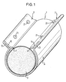
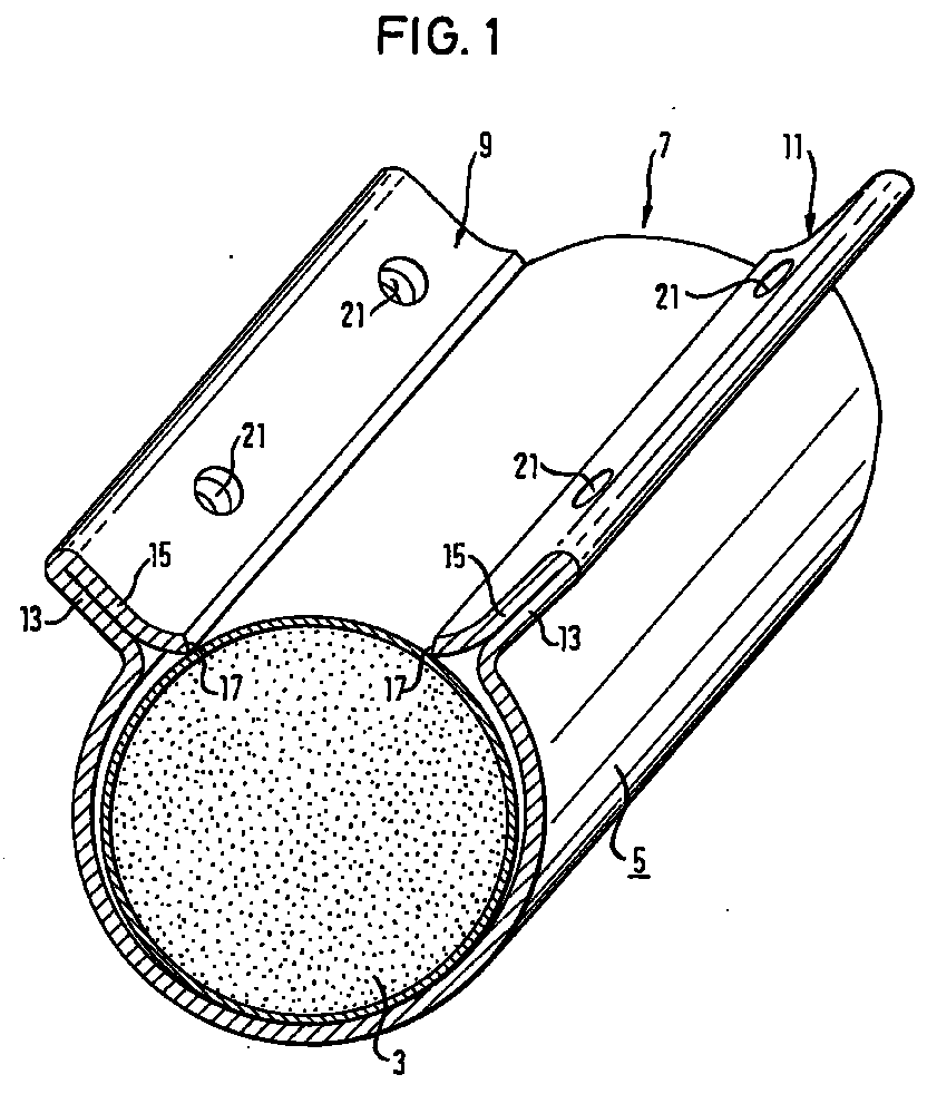
- an airbag module which is a conventional tubular Has gas generator 3.
- the gas generator 3 is one trough-shaped mounting housing 5 surrounded by sheet metal, which for fastening of the gas generator 3 on the vehicle. Due to the shape of the gutter there is a longitudinal slot 7, the opposite walls 9 and 11th of the mounting housing 5 is limited.
- the walls 9, 11, the side protrude outwards, are double-layered by U-shaped bending.
- the two layers 13, 15 of each wall 9, 11 can even abut each other.
- the end edge 17 presses the gas generator 3 in the mounting housing 5 and thereby clamps it. Between the two End edges 17 and the gas generator 5 results in a line contact over the entire length of the gas generator 3.
- the walls 9, 11 also serve as flanges for fastening the Mounting housing 5 on the vehicle. There are several mounting holes for this 21 provided in the walls 9, 11, which through both layers 13, 15th go through each wall 9, 11.
- the walls 9, 11 close in the embodiment shown an obtuse angle with each other.
- the construction shown makes it easy to secure the position
- the gas generator 3 is locked in the assembly housing 5. even after several years of driving. Due to the U-shaped bend of the Walls 9, 11 spring elements are formed so that the end edges 17 bear with a prestressing force on the gas generator 3. Certain Settlement processes can not solve the gas generator 3 in the Guide assembly housing 5. Due to the spring action of the walls 9, 11 can the outer circumference of the gas generator 3 also certain tolerances subject to without affecting the attachment of the gas generator 3 in Mounting housing 5 has a negative impact.
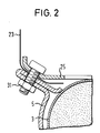
- the gas bag 23 indicated in FIG. 2 is placed over a its blowing part surrounding frame part 25 on the walls 9, 11 attached via screws / nut connections 31.
- the same screws / nut connections 31 serve also for attaching the gas bag module to the vehicle.
- Outflow openings in the gas generator 3, through which the gas generated the gas generator 3 flows out in the case of retention, can face and / or provided on the casing side in the gas generator 3.
Landscapes
- Engineering & Computer Science (AREA)
- Mechanical Engineering (AREA)
- Air Bags (AREA)
Abstract
Ein Gassack-Modul eines Fahrzeuginsassen-Rückhaltesystems, mit
einem im wesentlichen rohrförmigen Gasgenerator (3), einem den Gasgenerator
(3) umgebenden, mit einem Längsschlitz (7) versehenen,
rinnenförmigen Montagegehäuse (5) zur Befestigung des Gasgenerators
(3) am Fahrzeug und einem Gassack (23), ist dadurch gekennzeichnet,
daß die den Längsschlitz (7) begrenzenden, gegenüberliegenden
Wandungen (9, 11) des Montagegehäuses (5) jeweils U-förmig zu einer
Doppellage (13, 15) gebogen sind, daß sich jeweils die mit einem
Abschlußrand (17) versehene Lage (15) jeder Wandung (9, 11) in
Richtung des Gasgenerators (3) erstreckt und daß der Abschlußrand (17)
an dem Gasgenerator (3) anliegt.
Description
Die Erfindung betrifft ein Gassack-Modul eines Fabrzeuginsassen-Rückhaltesystems, mit einem im wesentlichen rohrförmigen Gasgenerator, einem den Gasgenerator umgebenden, mit einem Längsschlitz versehenen, rinnenförmigen Montagegehäuse zur Befestigung des Gasgenerators am Fahrzeug und einem Gassack.The invention relates to an airbag module of a fabric occupant restraint system, with an essentially tubular gas generator, a surrounding the gas generator, provided with a longitudinal slot, trough-shaped mounting housing for fastening the gas generator on Vehicle and an airbag.
Ein gattungsgemäßes Gassack-Modul ist aus der DE 44 15 374.0 bekannt. Dabei ist der Gasgenerator in ein schellenartiges Gehäuseteil eines kastenförmigen Druckgasbehälters geklemmt. Der Druckgasbehälter ist auf seiner Oberseite offen, und sein umlaufender Rand wird vom Saum der Berandung der Einblasöffnung des Gassacks hintergriffen.A generic airbag module is known from DE 44 15 374.0. The gas generator is in a clamp-like housing part a box-shaped compressed gas container clamped. The compressed gas tank is open at the top, and its peripheral edge is from the Gripped behind the edge of the air opening of the gas bag.
Darüber hinaus sind Gassack-Module bekannt, bei denen der den Einblasmund umgebende Gassackrand zwischen einem in dem Inneren des Gassacks angeordneten Rahmenteil und dem umlaufenden Rand eines Druckgasbehälters geklemmt wird.In addition, gas bag modules are known in which the The edge of the airbag surrounding the blowing mouth between one inside the Gas bag arranged frame part and the peripheral edge of a pressurized gas container is clamped.
Die Erfindung schafft ein Gassack-Modul, das aus weniger Einzelteilen besteht und schnell montiert werden kann. The invention creates an airbag module that consists of fewer individual parts exists and can be assembled quickly.
Dies wird bei einem Gassack-Modul der eingangs genannten Art dadurch erreicht, daß die den Längsschlitz begrenzenden, gegenüberliegenden Wandungen des Montagegehäuses jeweils U-förmig zu einer Doppellage gebogen sind, daß sich jeweils die mit einem Abschlußrand versehene Lage jeder Wandung in Richtung des Gasgenerators erstreckt und daß der Abschlußrand an dem Gasgenerator anliegt. Separate Schellen zur Befestigung des Gasgenerators sind beim erfindungsgemäßen Gassack-Modul nicht mehr erforderlich. Durch die U-Form erhalten die Wandungen eine ausgezeichnete elastische Nachgiebigkeit, wodurch ihr Abschlußrand stets mit einer gewissen Mindestkraft gegen den Gasgenerator drückt.This is the case with an airbag module of the type mentioned at the outset achieves that the opposite, delimiting the longitudinal slot Walls of the mounting housing each U-shaped to a double layer are curved so that each with a border Location of each wall extends in the direction of the gas generator and that the edge of the abutment lies against the gas generator. Separate clamps to attach the gas generator in the gas bag module according to the invention not necessary anymore. The U shape gives the walls excellent elastic resilience, which makes its edge always with a certain minimum force against the gas generator presses.
Gemäß einer bevorzugten Ausführungsform erstrecken sich die doppellagigen Wandungen seitlich nach außen und bilden zwei Flansche zur Befestigung des Montagegehäuses am Fahrzeug. Die Wandungen haben damit eine Doppelfunktion, indem sie einerseits für die Klemmung des Gasgenerators sorgen und andererseits als Flansche zur Befestigung dienen. Zudem werden, wenn die Flansche z.B. am Fahrzeug angeschraubt werden, die beiden Lagen der Wandung gegeneinandergepreßt, so daß die nach innen gerichteten Abschlußränder noch stärker gegen den Gasgenerator gedrückt werden. Das Montagegehäuse zeichnet sich durch ein geringes Gewicht aus, denn separat angeschweißte oder angeformte Flansche sind nicht notwendig. Der Gasgenerator ist am Montagegehäuse befestigt und nicht unmittelbar auch mit dem Gassack, so daß Gassack und Gasgenerator einen gewissen Abstand voneinander aufweisen können und der Einblasmund in einen Bereich gelegt werden kann, in dem er durch das ausströmende Gas thermisch geringer belastet wird.According to a preferred embodiment, the double-layered Walls laterally outwards and form two flanges Fastening the assembly housing to the vehicle. The walls have with it a double function, by acting on the one hand for clamping the gas generator care and on the other hand serve as flanges for attachment. In addition, if the flanges e.g. be screwed onto the vehicle, the two layers of the wall pressed against each other, so that the after inside edges even stronger against the gas generator be pressed. The mounting housing is characterized by a small Weight off, because there are separately welded or molded flanges unnecessary. The gas generator is attached to the mounting housing and not directly with the gas bag, so that gas bag and gas generator can have a certain distance from each other and the blowing mouth can be placed in an area where the outflowing gas is thermally less loaded.
Weitere Merkmale und Vorteile der Erfindung ergeben sich aus der
nachfolgenden Beschreibung und aus den nachfolgenden Zeichnungen, auf
die Bezug genommen wird. In den Zeichnungen zeigen:
In Fig. 1 ist ein Gassack-Modul gezeigt, das einen üblichen rohrförmigen
Gasgenerator 3 aufweist. Der Gasgenerator 3 ist von einem
rinnenförmigen Montagegehäuse 5 aus Blech umgeben, das zur Befestigung
des Gasgenerators 3 am Fahrzeug dient. Durch die Rinnenform ergibt
sich ein Längsschlitz 7, der von gegenüberliegenden Wandungen 9 und 11
des Montagegehäuses 5 begrenzt ist. Die Wandungen 9, 11, die seitlich
nach außen abstehen, sind durch U-förmiges Biegen doppellagig ausgebildet.
Die beiden Lagen 13, 15 jeder Wandung 9, 11 können dabei sogar
aneinander anliegen. Jede Lage 15, die auch den Abschlußrand 17, also
das umfangsseitige Ende des Montagegehäuses 5 aufweist, ragt in Richtung
zum Gasgenerator 3. Der Abschlußrand 17 drückt den Gasgenerator 3
in das Montagegehäuse 5 und klemmt ihn dadurch. Zwischen den beiden
Abschlußrändern 17 und dem Gasgenerator 5 ergibt sich eine Linienberührung
über die gesamte Länge des Gasgenerators 3.In Fig. 1, an airbag module is shown, which is a conventional tubular
Die Wandungen 9, 11 dienen auch als Flansche zur Befestigung des
Montagegehäuses 5 am Fahrzeug. Hierzu sind mehrere Befestigungsöffnungen
21 in den Wandungen 9, 11 vorgesehen, die durch beide Lagen 13, 15
jeder Wandung 9, 11 hindurchgehen. Die Wandungen 9, 11 schließen in
der gezeigten Ausführungsform einen stumpfen Winkel miteinander ein.
Beim Anschrauben des Montagegehäuses 5 an das Armaturenbrett wird die
Lage 13 gegen einen entsprechenden Flansch am Fahrzeug gepreßt, so daß
die Abschlußränder 17 noch weiter nach innen gedrückt werden und damit
eine höhere Klemmkraft auf den Gasgenerator 3 ausüben. Die Abschlußränder
17 können scharfkantig oder, wie in Fig. 2 gezeigt, mit einer
Abkantung ausgebildet sein.The
Durch die gezeigte Konstruktion wird auf einfache Weise eine lagesichere
Arretierung des Gasgenerators 3 im Montagegehäuse 5 erreicht,
auch nach mehreren Jahren Fahrbetrieb. Durch die U-förmige Biegung der
Wandungen 9, 11 werden Federelemente gebildet, so daß die Abschlußränder
17 mit einer Vorspannkraft am Gasgenerator 3 anliegen. Gewisse
Setzungsvorgänge können dadurch nicht zum Lösen des Gasgenerators 3 im
Montagegehäuse 5 führen. Durch die Federwirkung der Wandungen 9, 11
kann der Außenumfang des Gasgenerators 3 auch gewissen Toleranzen
unterliegen, ohne daß dies auf die Befestigung des Gasgenerators 3 im
Montagegehäuse 5 eine negative Auswirkung hat. The construction shown makes it easy to secure the position
The
Der in Fig. 2 angedeutete Gassack 23 wird über ein in ihn eingelegtes,
seinen Einblasmund umgebendes Rahmenteil 25 an den Wandungen
9, 11 über Schrauben/Mutternverbindungen 31 befestigt. Hierzu wird der
den Einblasmund berandende Wandungsabschnitt zwischen dem Rahmenteil
25 und den Wandungen 9, 11, genauer gesagt der Lage 15 jeder Wandung
9, 11, geklemmt. Dieselben Schrauben/Mutternverbindungen 31 dienen
auch zum Befestigen des Gassack-Moduls am Fahrzeug.The
Ausströmöffnungen im Gasgenerator 3, über die das erzeugte Gas aus
dem Gasgenerator 3 im Rückhaltefall ausströmt, können stirnseitig
und/oder mantelseitig im Gasgenerator 3 vorgesehen sein.Outflow openings in the
Claims (6)
Applications Claiming Priority (2)
| Application Number | Priority Date | Filing Date | Title |
|---|---|---|---|
| DE29701063U DE29701063U1 (en) | 1997-01-22 | 1997-01-22 | Airbag module |
| DE29701063U | 1997-01-22 |
Publications (3)
| Publication Number | Publication Date |
|---|---|
| EP0855314A2 true EP0855314A2 (en) | 1998-07-29 |
| EP0855314A3 EP0855314A3 (en) | 2000-01-05 |
| EP0855314B1 EP0855314B1 (en) | 2004-05-26 |
Family
ID=8034899
Family Applications (1)
| Application Number | Title | Priority Date | Filing Date |
|---|---|---|---|
| EP97122052A Expired - Lifetime EP0855314B1 (en) | 1997-01-22 | 1997-12-15 | Air bag module |
Country Status (4)
| Country | Link |
|---|---|
| US (1) | US5979930A (en) |
| EP (1) | EP0855314B1 (en) |
| JP (1) | JPH10203285A (en) |
| DE (2) | DE29701063U1 (en) |
Families Citing this family (3)
| Publication number | Priority date | Publication date | Assignee | Title |
|---|---|---|---|---|
| JPH1185304A (en) * | 1997-09-03 | 1999-03-30 | Nec Corp | Clock input control circuit |
| DE29801104U1 (en) * | 1998-01-23 | 1998-05-20 | Trw Occupant Restraint Systems Gmbh, 73551 Alfdorf | Gas generator |
| DE20018665U1 (en) | 2000-11-02 | 2001-03-08 | TRW Occupant Restraint Systems GmbH & Co. KG, 73553 Alfdorf | Generator support for cylindrical gas generator |
Family Cites Families (8)
| Publication number | Priority date | Publication date | Assignee | Title |
|---|---|---|---|---|
| US3708181A (en) * | 1970-08-19 | 1973-01-02 | Ara Inc | Construction for safety air cushion system |
| US5332256A (en) * | 1992-02-24 | 1994-07-26 | Morton International, Inc. | Continuous circumference diffuser reaction canister |
| US5509686A (en) * | 1992-05-04 | 1996-04-23 | General Motors Corporation | Inflatable restraint system with gas augmentation |
| DE4415374A1 (en) * | 1994-05-02 | 1995-11-09 | Trw Repa Gmbh | Airbag module |
| US5560643A (en) * | 1995-05-24 | 1996-10-01 | Morton International, Inc. | Airbag module with clamped attachment of airbag cushion |
| DE19532768A1 (en) * | 1995-09-05 | 1997-03-06 | Trw Repa Gmbh | Gas bag retainer module |
| EP0774387A3 (en) * | 1995-11-15 | 1999-01-07 | Morton International, Inc. | Airbag flow diversion walls for hot deployment performance levelling |
| DE29613269U1 (en) * | 1996-07-31 | 1996-11-28 | Trw Occupant Restraint Systems Gmbh, 73551 Alfdorf | Airbag module for a vehicle occupant restraint system |
-
1997
- 1997-01-22 DE DE29701063U patent/DE29701063U1/en not_active Expired - Lifetime
- 1997-12-15 DE DE59711668T patent/DE59711668D1/en not_active Expired - Fee Related
- 1997-12-15 EP EP97122052A patent/EP0855314B1/en not_active Expired - Lifetime
- 1997-12-30 US US09/001,060 patent/US5979930A/en not_active Expired - Fee Related
-
1998
- 1998-01-21 JP JP10023760A patent/JPH10203285A/en active Pending
Also Published As
| Publication number | Publication date |
|---|---|
| DE29701063U1 (en) | 1997-05-22 |
| DE59711668D1 (en) | 2004-07-01 |
| JPH10203285A (en) | 1998-08-04 |
| EP0855314B1 (en) | 2004-05-26 |
| EP0855314A3 (en) | 2000-01-05 |
| US5979930A (en) | 1999-11-09 |
Similar Documents
| Publication | Publication Date | Title |
|---|---|---|
| DE102004056956B4 (en) | Construction for a bumper reinforcement | |
| DE69612691T2 (en) | Energy absorbing cladding component | |
| DE4338666C2 (en) | Airbag housing and its attachment | |
| EP1110809A2 (en) | Vehicle seat, especially motor vehicle seat | |
| DE10297288B4 (en) | Tab for adjusting the Z-height of an airbag module | |
| EP2123918A2 (en) | Fastening device | |
| DE102008030341A1 (en) | Rear fender assembly | |
| DE29806080U1 (en) | Handle console | |
| DE102013225661A1 (en) | Lower structure of a center column of a vehicle | |
| DE10037690A1 (en) | Airbag device and housing thereof | |
| DE4134673C1 (en) | ||
| DE4424475C2 (en) | Cover for an airbag module | |
| EP1251042B1 (en) | Airbag module | |
| DE19621397B4 (en) | airbag module | |
| DE10041763B4 (en) | Airbag attaching | |
| DE10150275A1 (en) | Housing for inflatable airbag has gas generator fixed inside diffuser by form-locking and/or mechanically locking connection with inner wall of diffuser chamber | |
| EP0855314B1 (en) | Air bag module | |
| DE29901286U1 (en) | Bending hook | |
| DE10135848A1 (en) | Motor vehicle door incorporates a sealing element which by means of fixing elements is attached to the door inner sheet or the door lining for purposes of a preliminary assembly | |
| DE19535980A1 (en) | Airbag module fitted in vehicle | |
| DE19718211A1 (en) | Enclosure for front passenger airbag module | |
| AT402626B (en) | DEVICE FOR THE APPEARANCE FROM THE OUTSIDE DEVICE FOR THE APPLICATION OF SHEETS, SUCH AS e.g. PARKING LIGHTS APPLICATION OF LIGHTS LIKE PARKING LICENSE INSIDE AN AUTOMOTIVE INSIDE AN AUTOMOTIVE | |
| DE10113622B4 (en) | Device for transporting objects in a motor vehicle | |
| DE19839734C1 (en) | Holder for motor vehicle's accessory equipment, such as fire extinguisher, and suchlike, has base holder formed as four-sided profiled element with one side for installation on vehicle, and other sides equipped with fittings | |
| BE1031455B1 (en) | holding frame for a connector |
Legal Events
| Date | Code | Title | Description |
|---|---|---|---|
| PUAI | Public reference made under article 153(3) epc to a published international application that has entered the european phase |
Free format text: ORIGINAL CODE: 0009012 |
|
| AK | Designated contracting states |
Kind code of ref document: A2 Designated state(s): DE ES FR GB IT |
|
| AX | Request for extension of the european patent |
Free format text: AL;LT;LV;MK;RO;SI |
|
| PUAL | Search report despatched |
Free format text: ORIGINAL CODE: 0009013 |
|
| AK | Designated contracting states |
Kind code of ref document: A3 Designated state(s): AT BE CH DE DK ES FI FR GB GR IE IT LI LU MC NL PT SE |
|
| AX | Request for extension of the european patent |
Free format text: AL;LT;LV;MK;RO;SI |
|
| RIC1 | Information provided on ipc code assigned before grant |
Free format text: 7B 60R 21/16 A, 7B 60R 21/20 B |
|
| 17P | Request for examination filed |
Effective date: 20000418 |
|
| AKX | Designation fees paid |
Free format text: DE ES FR GB IT |
|
| GRAP | Despatch of communication of intention to grant a patent |
Free format text: ORIGINAL CODE: EPIDOSNIGR1 |
|
| GRAS | Grant fee paid |
Free format text: ORIGINAL CODE: EPIDOSNIGR3 |
|
| GRAA | (expected) grant |
Free format text: ORIGINAL CODE: 0009210 |
|
| RAP1 | Party data changed (applicant data changed or rights of an application transferred) |
Owner name: TRW AUTOMOTIVE GMBH |
|
| AK | Designated contracting states |
Kind code of ref document: B1 Designated state(s): DE ES FR GB IT |
|
| PG25 | Lapsed in a contracting state [announced via postgrant information from national office to epo] |
Ref country code: GB Free format text: LAPSE BECAUSE OF FAILURE TO SUBMIT A TRANSLATION OF THE DESCRIPTION OR TO PAY THE FEE WITHIN THE PRESCRIBED TIME-LIMIT Effective date: 20040526 Ref country code: FR Free format text: LAPSE BECAUSE OF NON-PAYMENT OF DUE FEES Effective date: 20040526 |
|
| REG | Reference to a national code |
Ref country code: GB Ref legal event code: FG4D Free format text: NOT ENGLISH |
|
| REF | Corresponds to: |
Ref document number: 59711668 Country of ref document: DE Date of ref document: 20040701 Kind code of ref document: P |
|
| PG25 | Lapsed in a contracting state [announced via postgrant information from national office to epo] |
Ref country code: ES Free format text: LAPSE BECAUSE OF FAILURE TO SUBMIT A TRANSLATION OF THE DESCRIPTION OR TO PAY THE FEE WITHIN THE PRESCRIBED TIME-LIMIT Effective date: 20040906 |
|
| GBV | Gb: ep patent (uk) treated as always having been void in accordance with gb section 77(7)/1977 [no translation filed] |
Effective date: 20040526 |
|
| PGFP | Annual fee paid to national office [announced via postgrant information from national office to epo] |
Ref country code: DE Payment date: 20041230 Year of fee payment: 8 |
|
| PLBE | No opposition filed within time limit |
Free format text: ORIGINAL CODE: 0009261 |
|
| STAA | Information on the status of an ep patent application or granted ep patent |
Free format text: STATUS: NO OPPOSITION FILED WITHIN TIME LIMIT |
|
| 26N | No opposition filed |
Effective date: 20050301 |
|
| EN | Fr: translation not filed | ||
| PG25 | Lapsed in a contracting state [announced via postgrant information from national office to epo] |
Ref country code: IT Free format text: LAPSE BECAUSE OF NON-PAYMENT OF DUE FEES;WARNING: LAPSES OF ITALIAN PATENTS WITH EFFECTIVE DATE BEFORE 2007 MAY HAVE OCCURRED AT ANY TIME BEFORE 2007. THE CORRECT EFFECTIVE DATE MAY BE DIFFERENT FROM THE ONE RECORDED. Effective date: 20051215 |
|
| PG25 | Lapsed in a contracting state [announced via postgrant information from national office to epo] |
Ref country code: DE Free format text: LAPSE BECAUSE OF NON-PAYMENT OF DUE FEES Effective date: 20060701 |