EP0855340A2 - Dégriveur hybride comportant des éléments contrÔlées séquenciellement - Google Patents
Dégriveur hybride comportant des éléments contrÔlées séquenciellement Download PDFInfo
- Publication number
- EP0855340A2 EP0855340A2 EP98300424A EP98300424A EP0855340A2 EP 0855340 A2 EP0855340 A2 EP 0855340A2 EP 98300424 A EP98300424 A EP 98300424A EP 98300424 A EP98300424 A EP 98300424A EP 0855340 A2 EP0855340 A2 EP 0855340A2
- Authority
- EP
- European Patent Office
- Prior art keywords
- deicer
- skin
- accordance
- area
- outer skin
- Prior art date
- Legal status (The legal status is an assumption and is not a legal conclusion. Google has not performed a legal analysis and makes no representation as to the accuracy of the status listed.)
- Withdrawn
Links
- 238000010438 heat treatment Methods 0.000 claims abstract description 43
- 238000000926 separation method Methods 0.000 claims description 24
- XLYOFNOQVPJJNP-UHFFFAOYSA-N water Substances O XLYOFNOQVPJJNP-UHFFFAOYSA-N 0.000 claims description 24
- 230000001351 cycling effect Effects 0.000 claims description 9
- 238000000034 method Methods 0.000 claims description 9
- 230000015572 biosynthetic process Effects 0.000 abstract description 5
- 239000000463 material Substances 0.000 description 27
- 239000004020 conductor Substances 0.000 description 22
- 238000012360 testing method Methods 0.000 description 12
- 230000003628 erosive effect Effects 0.000 description 11
- 230000003247 decreasing effect Effects 0.000 description 10
- 229920002430 Fibre-reinforced plastic Polymers 0.000 description 7
- 229910052782 aluminium Inorganic materials 0.000 description 7
- XAGFODPZIPBFFR-UHFFFAOYSA-N aluminium Chemical compound [Al] XAGFODPZIPBFFR-UHFFFAOYSA-N 0.000 description 7
- 238000010586 diagram Methods 0.000 description 7
- 239000011151 fibre-reinforced plastic Substances 0.000 description 7
- 230000000712 assembly Effects 0.000 description 6
- 238000000429 assembly Methods 0.000 description 6
- 230000007423 decrease Effects 0.000 description 6
- 230000000694 effects Effects 0.000 description 6
- 230000005672 electromagnetic field Effects 0.000 description 6
- 229910052751 metal Inorganic materials 0.000 description 6
- 239000002184 metal Substances 0.000 description 6
- 239000004744 fabric Substances 0.000 description 5
- 238000012546 transfer Methods 0.000 description 5
- 230000001133 acceleration Effects 0.000 description 4
- 230000003213 activating effect Effects 0.000 description 4
- 238000013461 design Methods 0.000 description 4
- 238000006073 displacement reaction Methods 0.000 description 4
- 238000005265 energy consumption Methods 0.000 description 4
- 230000004044 response Effects 0.000 description 4
- 229920003051 synthetic elastomer Polymers 0.000 description 4
- 239000005061 synthetic rubber Substances 0.000 description 4
- 230000001052 transient effect Effects 0.000 description 4
- RYGMFSIKBFXOCR-UHFFFAOYSA-N Copper Chemical compound [Cu] RYGMFSIKBFXOCR-UHFFFAOYSA-N 0.000 description 3
- 239000004593 Epoxy Substances 0.000 description 3
- 239000004696 Poly ether ether ketone Substances 0.000 description 3
- RTAQQCXQSZGOHL-UHFFFAOYSA-N Titanium Chemical compound [Ti] RTAQQCXQSZGOHL-UHFFFAOYSA-N 0.000 description 3
- 229920001971 elastomer Polymers 0.000 description 3
- 230000001965 increasing effect Effects 0.000 description 3
- 229920001778 nylon Polymers 0.000 description 3
- 229920003023 plastic Polymers 0.000 description 3
- 239000004033 plastic Substances 0.000 description 3
- 229920002530 polyetherether ketone Polymers 0.000 description 3
- 239000004814 polyurethane Substances 0.000 description 3
- 229920002635 polyurethane Polymers 0.000 description 3
- 230000008569 process Effects 0.000 description 3
- 230000003014 reinforcing effect Effects 0.000 description 3
- 239000005060 rubber Substances 0.000 description 3
- 229920000049 Carbon (fiber) Polymers 0.000 description 2
- 241001424392 Lucia limbaria Species 0.000 description 2
- 239000004677 Nylon Substances 0.000 description 2
- 101000798429 Pinus strobus Putative 2-Cys peroxiredoxin BAS1 Proteins 0.000 description 2
- 230000004913 activation Effects 0.000 description 2
- 230000008901 benefit Effects 0.000 description 2
- 239000007767 bonding agent Substances 0.000 description 2
- 239000004917 carbon fiber Substances 0.000 description 2
- 229910052802 copper Inorganic materials 0.000 description 2
- 239000010949 copper Substances 0.000 description 2
- 238000002474 experimental method Methods 0.000 description 2
- 239000011888 foil Substances 0.000 description 2
- 230000001939 inductive effect Effects 0.000 description 2
- 229920003052 natural elastomer Polymers 0.000 description 2
- 229920001194 natural rubber Polymers 0.000 description 2
- 239000002985 plastic film Substances 0.000 description 2
- 229920006255 plastic film Polymers 0.000 description 2
- 229920001084 poly(chloroprene) Polymers 0.000 description 2
- 230000001012 protector Effects 0.000 description 2
- 239000003381 stabilizer Substances 0.000 description 2
- 239000010936 titanium Substances 0.000 description 2
- 229910052719 titanium Inorganic materials 0.000 description 2
- RZVHIXYEVGDQDX-UHFFFAOYSA-N 9,10-anthraquinone Chemical compound C1=CC=C2C(=O)C3=CC=CC=C3C(=O)C2=C1 RZVHIXYEVGDQDX-UHFFFAOYSA-N 0.000 description 1
- OKTJSMMVPCPJKN-UHFFFAOYSA-N Carbon Chemical compound [C] OKTJSMMVPCPJKN-UHFFFAOYSA-N 0.000 description 1
- 229920000271 Kevlar® Polymers 0.000 description 1
- 229910001069 Ti alloy Inorganic materials 0.000 description 1
- 230000035508 accumulation Effects 0.000 description 1
- 238000009825 accumulation Methods 0.000 description 1
- 230000009471 action Effects 0.000 description 1
- 239000000853 adhesive Substances 0.000 description 1
- 230000001070 adhesive effect Effects 0.000 description 1
- 230000002411 adverse Effects 0.000 description 1
- 238000013459 approach Methods 0.000 description 1
- 238000009529 body temperature measurement Methods 0.000 description 1
- 239000004568 cement Substances 0.000 description 1
- 238000006243 chemical reaction Methods 0.000 description 1
- 239000012141 concentrate Substances 0.000 description 1
- 230000001143 conditioned effect Effects 0.000 description 1
- 238000010276 construction Methods 0.000 description 1
- 239000011889 copper foil Substances 0.000 description 1
- 238000004146 energy storage Methods 0.000 description 1
- 230000001747 exhibiting effect Effects 0.000 description 1
- 239000000835 fiber Substances 0.000 description 1
- 239000011152 fibreglass Substances 0.000 description 1
- 239000010408 film Substances 0.000 description 1
- 239000011521 glass Substances 0.000 description 1
- 239000003365 glass fiber Substances 0.000 description 1
- 229910002804 graphite Inorganic materials 0.000 description 1
- 239000010439 graphite Substances 0.000 description 1
- 230000001976 improved effect Effects 0.000 description 1
- 238000009434 installation Methods 0.000 description 1
- 239000004761 kevlar Substances 0.000 description 1
- 238000004519 manufacturing process Methods 0.000 description 1
- 238000005259 measurement Methods 0.000 description 1
- 230000007246 mechanism Effects 0.000 description 1
- VNWKTOKETHGBQD-UHFFFAOYSA-N methane Chemical compound C VNWKTOKETHGBQD-UHFFFAOYSA-N 0.000 description 1
- 239000003973 paint Substances 0.000 description 1
- 239000002245 particle Substances 0.000 description 1
- 229920003225 polyurethane elastomer Polymers 0.000 description 1
- 229920006264 polyurethane film Polymers 0.000 description 1
- 238000003825 pressing Methods 0.000 description 1
- 238000012545 processing Methods 0.000 description 1
- 239000002990 reinforced plastic Substances 0.000 description 1
- 230000001846 repelling effect Effects 0.000 description 1
- 230000000630 rising effect Effects 0.000 description 1
- 239000004576 sand Substances 0.000 description 1
- 239000010935 stainless steel Substances 0.000 description 1
- 229910001220 stainless steel Inorganic materials 0.000 description 1
- 239000010409 thin film Substances 0.000 description 1
Images




Classifications
-
- B—PERFORMING OPERATIONS; TRANSPORTING
- B64—AIRCRAFT; AVIATION; COSMONAUTICS
- B64D—EQUIPMENT FOR FITTING IN OR TO AIRCRAFT; FLIGHT SUITS; PARACHUTES; ARRANGEMENT OR MOUNTING OF POWER PLANTS OR PROPULSION TRANSMISSIONS IN AIRCRAFT
- B64D15/00—De-icing or preventing icing on exterior surfaces of aircraft
- B64D15/16—De-icing or preventing icing on exterior surfaces of aircraft by mechanical means, e.g. pulsating mats or shoes attached to, or built into, surface
- B64D15/163—De-icing or preventing icing on exterior surfaces of aircraft by mechanical means, e.g. pulsating mats or shoes attached to, or built into, surface using electro-impulsive devices
-
- B—PERFORMING OPERATIONS; TRANSPORTING
- B64—AIRCRAFT; AVIATION; COSMONAUTICS
- B64D—EQUIPMENT FOR FITTING IN OR TO AIRCRAFT; FLIGHT SUITS; PARACHUTES; ARRANGEMENT OR MOUNTING OF POWER PLANTS OR PROPULSION TRANSMISSIONS IN AIRCRAFT
- B64D15/00—De-icing or preventing icing on exterior surfaces of aircraft
-
- B—PERFORMING OPERATIONS; TRANSPORTING
- B64—AIRCRAFT; AVIATION; COSMONAUTICS
- B64D—EQUIPMENT FOR FITTING IN OR TO AIRCRAFT; FLIGHT SUITS; PARACHUTES; ARRANGEMENT OR MOUNTING OF POWER PLANTS OR PROPULSION TRANSMISSIONS IN AIRCRAFT
- B64D15/00—De-icing or preventing icing on exterior surfaces of aircraft
- B64D15/12—De-icing or preventing icing on exterior surfaces of aircraft by electric heating
-
- B—PERFORMING OPERATIONS; TRANSPORTING
- B64—AIRCRAFT; AVIATION; COSMONAUTICS
- B64D—EQUIPMENT FOR FITTING IN OR TO AIRCRAFT; FLIGHT SUITS; PARACHUTES; ARRANGEMENT OR MOUNTING OF POWER PLANTS OR PROPULSION TRANSMISSIONS IN AIRCRAFT
- B64D15/00—De-icing or preventing icing on exterior surfaces of aircraft
- B64D15/12—De-icing or preventing icing on exterior surfaces of aircraft by electric heating
- B64D15/14—De-icing or preventing icing on exterior surfaces of aircraft by electric heating controlled cyclically along length of surface
-
- B—PERFORMING OPERATIONS; TRANSPORTING
- B64—AIRCRAFT; AVIATION; COSMONAUTICS
- B64D—EQUIPMENT FOR FITTING IN OR TO AIRCRAFT; FLIGHT SUITS; PARACHUTES; ARRANGEMENT OR MOUNTING OF POWER PLANTS OR PROPULSION TRANSMISSIONS IN AIRCRAFT
- B64D15/00—De-icing or preventing icing on exterior surfaces of aircraft
- B64D15/16—De-icing or preventing icing on exterior surfaces of aircraft by mechanical means, e.g. pulsating mats or shoes attached to, or built into, surface
- B64D15/166—De-icing or preventing icing on exterior surfaces of aircraft by mechanical means, e.g. pulsating mats or shoes attached to, or built into, surface using pneumatic boots
Definitions
- This invention relates to deicers that remove ice accumulated on various aircraft surfaces during flight in atmospheric icing conditions, and more particularly to deicers which utilize both dynamic motion to expel the ice and thermal energy to melt the ice.
- a class of systems has been developed that utilize skin deflection means to dynamically activate a thin deflectable outer skin upon which ice accumulates.
- the dynamic activation induces rapid motion in the thin deflectable kin sufficient to dynamically debond, shatter and expel an accumulated ice cap into surrounding airflow.
- the skin deflection means can take a variety of forms.
- the skin deflection means are combined with the thin deflectable outer skin to form a unitary deicer.
- the unitary deicer is generally formed in a thin sheet that can be subsequently bonded to the leading edge surface of an existing aircraft structure.
- the deicer is usually designed to be removed from the aircraft structure and replaced in the field requiring the use of a replaceable adhesive such as 3M 1300L rubber cement. Examples are presented in United States Patent 4,706,911 METHOD AND APPARATUS FOR DEICING A LEADING EDGE, Briscoe et al.
- the skin deflection means are combined with the thin deflectable outer skin and a reinforcing structure thereby forming a unitary leading edge structure with integral de-icing capability.
- the deicer is permanently bonded to the reinforcing structure necessitating replacement of the entire assembly upon failure of the deicer.
- An example of this type of device is presented in United States Patent 5,098,037 STRUCTURAL AIRFOIL HAVING INTEGRAL EXPULSIVE SYSTEM, Leffel et al. (hereinafter referred to as the Integral Expulsive System Patent).
- the structure to which the deicer is attached will be referred to as the "substructure.”
- substructures include an existing aircraft structure having a leading edge surface and a reinforcing structure as discussed above.
- the skin deflection means can take a variety of forms.
- the skin deflection means comprises an upper array of conductors and a lower array of conductors.
- the upper conductors are substantially parallel to each other and to adjacent conductors in the lower layer.
- the upper conductors are connected in series with the lower conductors so that a single continuous conductor is formed that passes from the upper layer, around the lower layer, back around the upper layer, and so on.
- current is developed in the upper conductors that is in the same direction in all upper conductors.
- the upper and lower conductors are sandwiched between the structural member and a surface ply (the surface ply is analogous to a thin deflectable skin).
- the surface ply is analogous to a thin deflectable skin.
- opposing electromagnetic fields in the upper and lower layers forcefully repel each other. This motion induces a dynamic motion into the surface ply which dynamically removes accumulated ice.
- a current pulse that rises to between 2300 and 3100 amperes within 100 microseconds generates effective ice removal.
- a circuit for generating such a pulse is described in the Electro-Repulsive Patent.
- the circuit includes a pulse forming network, but this is not absolutely necessary.
- Electro-Impulse Patent Another form for the skin deflection means utilizing electromagnetic apparatus is illustrated by the Electro-Impulse Patent.
- a planar coil comprising at least one coiled conductor is sandwiched between a surface ply and a conductive substructure (such as the leading edge of an aluminum aircraft structure). Planar coils are described in great detail in United States Patent 5,152,480 PLANAR COIL CONSTRUCTION, Adams et al. (hereinafter referred to as the Planar Coil Patent).
- a high magnitude short duration current pulse is applied to the coil.
- the current in the coil induces a strong rapidly changing electromagnetic field.
- the electromagnetic field generates eddy currents in the conductive substructure which, in turn, generates an opposing electromagnetic field.
- the two electromagnetic fields repel each other causing a repelling force between the coil and the substructure.
- the coil induces dynamic motion into the surface ply thereby dynamically removing accumulated ice.
- Effective ice removal is generated by a peak current of about 3000 amperes rising in a period of 100 microseconds.
- An electrical circuit for generating such a pulse is disclosed. The circuit is very similar to the circuit disclosed in the Electro-Repulsive Patent.
- the skin deflection means is composed of a single unitary planar coil.
- a target may also be required if the substructure does not have sufficient electrical conductivity to effectively develop eddy currents.
- a target would be required with a fiber reinforced plastic substructure, or a conductive substructure that is too thin to effectively develop eddy currents.
- the target is a sheet of conductive material such as copper or aluminum that is located adjacent one surface of the coil. The coil and target are forcefully repelled from each other upon application of a high magnitude short duration current pulse to the coil due to opposing magnetic fields generated by current in the coil and by eddy currents in the target. This motion induces dynamic motion into the surface ply which dynamically removes accumulated ice.
- the target can be formed as a part of the substructure or can be formed as a part of the thin force and displacement generation means. Also, as described in the Electro-Impulse Patent, either the target or the coil can be located immediately subjacent the outer skin. The target applies the motive force to the skin if it is located subjacent the skin. Conversely, the coil applies the motive force to the skin if it is located subjacent the skin.
- the Planar Coil Patent also teaches an electro-repulsive variation similar to the Electro-Repulsive Patent.
- Two mirror image unitary planar coils are superposed relative to each other and electrically connected so that upon application of a high magnitude short duration current pulse to each coil, current direction is opposite in each coil.
- Opposing electromagnetic fields are generated in the coils which causes each coil to forcefully repel the other. This motion induces a mechanical impulse into the surface ply which removes accumulated ice.
- This approach differs from the Electro-Repulsive Patent which utilizes a single conductor to form the upper and lower conductors.
- a type of skin deflection means that utilizes pressurized gas is described in the Pneumatic Impulse Patent and the Integral Expulsive System Patent.
- a plurality of pneumatic impulse tubes extend in a spanwise direction subjacent a thin deflectable outer skin.
- the tubes and skin are supported by a fiber reinforced plastic substructure which together form a leading edge structure with integral de-icing capability.
- Special fittings are integrated into the tubes at various locations spaced along the span of each tube.
- a pneumatic impulse valve is attached to each fitting.
- a suitable valve is described in United States Patent 4,878,647 PNEUMATIC IMPULSE VALVE AND SEPARATION SYSTEM, Putt et al.
- the valve contains a small volume (about 1 cubic inch) of high pressure air (500 to 5,000 psig).
- the valve Upon activation by a solenoid, the valve quickly releases the pressurized air into each tube via the fitting.
- the expanding air pulse causes the tube to expand and induce mechanical motion into the skin thereby dynamically expelling accumulated ice.
- the expanding air pulse most preferably inflates the tube in less than 500 microseconds.
- Electro-Repulsive Patent Electro-Impulse Patent
- Planar Coil Patent Pneumatic Impulse Patent
- Integrated Pneumatic Impulse Patent provide examples of the types of structure that can serve as skin deflection means.
- the skin deflection means generates a force that causes the skin to be deflected away from the substructure.
- These patents are intended to be merely representative, and the types of structures that can serve as skin deflection means is not limited to the specific teachings of these patents.
- the devices described above represent advancements over previous de-icing systems. In spite of these advancements, means of improving ice removal performance, life, reliability, weight, and energy consumption are of continuing interest. In particular, a deicer is desired exhibiting the excellent ice removal performance typical of the devices described above while having increased life, reduced weight, and reduced energy consumption.
- the invention comprises a deicer adapted for attachment to a substructure, the deicer having an outer skin that meets and breaks an impinging airstream when attached to the substructure, the substructure having an apex corresponding to the portion of the deicer and substructure underlying the area of the outer skin where the radius of curvature is smallest, the deicer comprising:
- FIG. 1 is a fragmentary sectional view of a deicer in accordance with a first embodiment of the present invention.
- FIG. 2 is a fragmentary sectional view of a deicer in accordance with a second embodiment of the present invention.
- FIG. 3 is an isometric view of a deicer incorporating electromagnetic apparatus attached to a substructure.
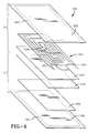
- FIG. 4 is an exploded isometric view of an electro-impulse embodiment for a skin deflection means.
- FIG. 5 is an exploded isometric view of an electro-repulsive embodiment for a skin deflection means.
- FIG. 6 is a plan view of an deicer having a parting strip and a plurality of deicing zones in accordance with the present invention.
- FIG. 7 is a simplified logic flow diagram illustrative if a routine for controlling a deicing system according to an aspect of the present invention.
- FIG. 8 is a simplified logic flow diagram illustrative if a routine for controlling a deicing system according to another aspect of the present invention.
- FIG. 9 is a simplified logic flow diagram illustrative if a routine for controlling a deicing system according to another aspect of the present invention.
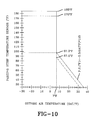
- FIG. 10 is a plot showing parting strip zone temperature setpoints versus outside air temperature.
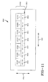
- FIG. 11 is a plan view of an deicer having a parting strip and a plurality of deicing zones in accordance with another aspect of the present invention.
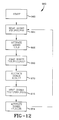
- FIG. 12 is a simplified logic flow diagram illustrative if a routine for controlling a deicing system according to another aspect of the present invention.
- a deicer 100 embodying the invention is shown attached to a substructure 102.
- Centerline 121 bisects deicer 100 and substructure 102 at the deicer apex 120.
- Deicer 100 and substructure 102 have a chordwise and spanwise direction. The chordwise direction is defined as being approximately parallel to the direction of an impinging airstream 119 as it passes around the deicer 100 and substructure 102.
- the deicer 100 and substructure 102 also extend in a spanwise direction which is generally perpendicular to the chordwise direction.
- the deicer and substructure can either be straight or have curvature in the spanwise direction.
- the spanwise direction corresponds to the circumference of the inlet.
- the spanwise curvature can generally be ignored. Therefore, for the purposes of this application, the term "curvature” refers only to curvature measured in the plane of the chordwise section.
- the section shown in Figure 1 is a chordwise cross-section.
- Deicer 100 has an outer surface 122 which meets and breaks the impinging airstream.
- the outer surface 122 has a radius of curvature R, measured perpendicular to the outer surface 122, that changes depending on the chordwise position along the outer surface 122.
- Deicer 100 comprises a thin deflectable skin 104, a skin heating means 101, and a skin deflection means 103.
- the skin deflection means 103 comprises four expandable tubes 107-111.
- the tubes are activated by sequentially releasing small quantities of compressed gas into each tube as described by the Integral Expulsive System Patent, U.S. 5,098,037, which is fully incorporated herein by reference.
- the skin deflection means 103 can also take forms utilizing electromagnetic apparatus. Examples are presented in U.S. Patent Nos 4,678,144, 5,129,598, 5,152,480, 5,047,497, 4,501,398, 5,553,815, and 5.429,327, the disclosures of which are fully incorporated herein by reference.
- Skin heating means 101 may be any of a number of heating apparatus known to those in the skilled in the art. Examples of such heating means are presented in U.S. Patent Nos 2,599,059, 2,992,317, 5,351.918, 5,475,204 and U.S. Patent Reexamination Certificate No. 4,386,749, the disclosures of which are fully incorporated herein by reference.
- skin heating means 101 divides the skin deflection means 102.
- the skin deflection means 102 are disposed adjacent the skin heating means 101.
- the substructure 102 provides the structural integrity necessary to absorb and resist flight loads and unexpected impacts with foreign objects.
- the substructure can be formed from a metal, such as aluminum, or fiber reinforced plastic materials that are commonly used on aircraft such as epoxy impregnated glass or graphite fabrics.
- the skin 104 includes a backing layer 105 and a layer of erosion resistant material 106.
- the backing layer 105 can be formed from fiber reinforced plastic material, such as nitrile phenolic or epoxy impregnated into a fabric composed of fibers belonging to one of a group including carbon fibers, glass fibers, and nylon fibers.
- the erosion layer 104 can be formed from rubber, metal, or plastic, such as neoprene, titanium foil, polyether-ether-ketone film, polyurethane film, and polyurethane paint depending on the application.
- the erosion layer 106 is necessary to provide resistance to impact from rain, sand, and other debris that would damage the backing layer 105.
- the skin 104 must have elastic properties.
- the term "elastic" refers to the tendency of a material to return entirely to its rest state within a short period of time after an imposed force is removed.
- the skin 104, skin deflection means 102, and substructure 102 can be permanently bonded together to form a unitary structure with integral ice removal capability as described in the Integral Expulsive System Patent. Alternatively, the skin 104 and skin deflection means 103 can combined into a unitary structure which is then attached to an existing aircraft substructure 102.
- Skin heating means 101 may be provided behind either the erosion layer 106 or the backing layer 105, and serves either to prevent the formation of ice on the erosion layer 106 over the heating means 101, or to melt ice which may have accumulated.
- the skin deflection means 103 consists of four expandable tubes 107-111.
- the expandable tubes 107-111 can be formed from fiber reinforced plastic material such as nitrile phenolic coated nylon fabric, or rubber coated fabric such as neoprene coated nylon fabric.
- the deicer 100 is activated by sequentially releasing small quantities of compressed air into the tubes 107-111 as described in the Pneumatic Impulse Patent or Integral Expulsive System Patent. Inflation of a tube is preferably achieved in less than 0.1 second and most preferably in less than 500 microseconds.
- Deicer 100 is shown in an activated state by inflation of tube 110. Tubes 107, 108 and 111 are shown not inflated. Rapid inflation of tube 110 deflects the skin 104 outward developing tension in skin 104. This movement must occur rapidly enough to debond and shatter the ice cap 115 and eject the side ice-pieces 118 into the impinging airstream 119 where they are swept away from the deicer 100. The compressed air is subsequently vented from tube 110, and the skin 104 snaps back to its rest position due to the elastic properties of the skin 104. The process is repeated by inflation of tube 108 resulting in removal of side ice-pieces 116.
- deicer 100 of Figure 1 achieves deflection of the skin 104 by two mechanisms; (1) stretching the skin 104 behind the apex of the airfoil, and (2) heating the skin over the apex of the airfoil.
- a certain maximum deflection 114 is necessary in order to achieve ice removal. The maximum deflection 114 depends on the materials and application, but generally ranges from 0.020 inch to 0.060 inch.
- Preventing ice formation over the apex of the deicer decreases the required level of force generation in the skin deflection means 103 necessary to achieving ice removal over the skin deflection means.
- Reducing the level of force generation in the skin deflection means 103 decreases the tension in skin 104. Stress in the skin deflection means 103 is reduced by decreasing the level of force generation. Likewise, stress in the skin 104 is reduced by reducing the level of tension. Therefore, the invention provides a means of reducing the stress levels in the components of a dynamic deicer. As discussed previously, reducing the stress levels increases life. The superior life resulting from the invention has been demonstrated in several bench tests.
- the decreased tension in skin 104 required to obtain a desired deflection also improves energy consumption and weight.
- the invention decreases stress in skin 104 and permits decreased force generation in the skin deflection means 103. Since less force is required, less material is required to absorb and distribute reaction forces from the skin deflection means 103.
- the substructure 102, skin deflection means 103, and skin 104 can all be lighter in weight since the invention reduces the force each must withstand.
- Pneumatic impulse valves of the type described in United States Patent 4,878,647 PNEUMATIC IMPULSE VALVE AND SEPARATION SYSTEM, Putt et al., are spaced along the spanwise length of a expandable tube (pneumatic impulse tube). The distance between valves depends on the pulse propagation distance as previously discussed in relation to deicers 100 and 200 of Figures 1 and 2. The pulse propagation distance of a deicer similar to deicers 100 or 200 is limited by the stiffness of the outer skin. The pulse propagation distance of deicer 100 is greater because the skin 104 of deicer 100 is easier to deflect.
- deicer 100 presents a further advantage since its active area is the same as the active area of deicer 100, but deicer 100 has only four tubes. In other words, deicer 100 would require only eight valves compared to the sixteen valves required by deicer 100. In this hypothetical example, the number of valves has been reduced by one-half. Reducing the number of valves reduces energy consumption, weight, cost, and complexity of the system. Fewer valves also increases the reliability because the resulting system has many fewer mechanical components.
- the invention also produces improvements in ice removal performance.
- the ice removal performance of a dynamic deicer is strongly related to how quickly the outer skin moves. As the movement rate of the surface increases, minimum ice removal thickness decreases along with the quantity of residual ice left after ice cap removal.
- the dynamic frequency response of a thin deflectable skin is increased by increasing its modulus of elasticity.
- Materials having an elevated modulus of elasticity and a tendency to transmit rather than damp dynamic motion are preferred.
- an "elevated modulus” means a modulus of elasticity greater than 40,000 kPa.
- desirable materials for the backing layer 115 include but are not limited to fiber reinforced plastics which are preferred over natural or synthetic rubbers. Fiberglass or carbon fiber reinforced nitrile phenolic or epoxy are particularly useful. Materials having less of a tendency to absorb and damp dynamic movement are also desirable in order to minimize the amount of impulse energy absorbed by the backing layer 115. As much of the impulse energy as possible should be transmitted to the ice layer. Kevlar generally is not desirable because of its tendency to absorb and damp the dynamic motion induced by the skin deflection means.
- mechanical properties of the layer of erosion resistant material also perform an important role in the ice removal performance of dynamic deicers.
- materials having an elevated modulus of elasticity and a tendency to transmit rather than damp dynamic motion exhibit the best ice removal properties.
- plastic films such as polyurethane or polyether-ether-ketone and metal foils such as titanium, aluminum, or stainless steel. These materials generally perform better than low modulus materials such as natural or synthetic rubber, and polyurethane elastomer. These materials exhibit better ice removal performance for two reasons. First, they generally have less of a tendency to absorb and damp the dynamic motion induced by the skin deflection means.
- Dynamic energy tends to be absorbed and dissipated in a low modulus erosion layer rather than being efficiently transmitted to the ice layer.
- Low modulus materials tend to distribute and dissipate the shear stresses along the interface. Elevated modulus materials tend to concentrate shear stresses along the interface. Examples of suitable materials include metal foils, such as titanium, or plastic films, such as polyether-ether-ketone or polyurethane.
- the skin materials should be selected from a group of materials having an elevated modulus and a tendency to transmit rather than damp dynamic motion.
- deflection of a high modulus skin requires more force with a deicer similar to deicers 100 or 200 than with a deicer similar to deicer 100 having a skin heating means 101. Decreasing the force increases the life of a dynamic deicer. Therefore, deicer 100 permits use of an elevated modulus skin 104, and the attendant ice removal performance, while maintaining lower stress levels and a longer life.
- ice removal over the apex of deicers 100 and 200 may prove unsatisfactory depending on the geometry. Specifically, removing ice over an apex from a surface having a radius of curvature less than 0.50 inch can be difficult. Removing ice over an apex having a radius of curvature less than 0.25 inch is particularly difficult. As evidenced by deicer 100, the invention provides a means whereby the ice removal over an apex is not an issue due to the ability of heating means 101 to prevent its formation entirely.
- the best skin deflection means arrangement depends on a variety of factors that can vary greatly depending on an airframe manufacturer's specifications. Such factors include, the leading edge geometry, flight characteristics, maximum thickness of ice chat can be tolerated, cost, life, reliability and weight.
- Figure 1 shows on arrangement, however, depending on the application, ice removal performance may require use of other arrangements.
- Optimizing the design is a process that iterates between bench testing and icing wind tunnel testing. Life tests, rain erosion tests, dynamic tests and icing wind tunnel tests are cyclically performed with an eye toward improving each property. Changing the design to improve one of these factors may have an adverse effect on another.
- the rain erosion test parameters described in the Integrated Pneumatic Impulse Patent are particularly useful for determining rain erosion characteristics.
- Dynamic tests can be considered as a subset of icing wind tunnel tests since improving skin dynamics usually improves ice removal performance.
- a Polytech Model No. OFV 100 laser vibrometer system has been found to be very effective for bench testing designs in order to determine dynamic displacements, velocities, and accelerations at various locations on the skin.
- a deicer 200 in accordance with an alternative embodiment of the present invention is shown attached to a substructure 202.
- Centerline 221 bisects deicer 200 and substructure 202 at the deicer apex 220.
- Deicer 200 and substructure 202 have a chordwise and spanwise direction.
- the chordwise direction is defined as being approximately parallel to the direction of an impinging airstream 219 as it passes around the deicer 200 and substructure 202.
- the deicer 200 and substructure 202 also extend in a spanwise direction which is generally perpendicular to the chordwise direction.
- the deicer and substructure can either be straight or have curvature in the spanwise direction.
- the section shown in Figure 2 is a chordwise cross-section.
- Deicer 200 has an outer surface 222 which meets and breaks the impinging airstream.
- the outer surface 222 has a radius of curvature R, measured perpendicular to the outer surface 222, that changes depending on the chordwise position along the outer surface 222.
- Deicer 200 comprises a thin deflectable skin 204, a skin heating means 201, and a skin deflection means 203.
- the skin deflection means 203 comprises an electro impulse deicer (EIDI) for inducing eddy currents in skin 205.
- EIDI electro impulse deicer
- a temperature sensor or transducer 50 is disposed adjacent the skin heating means 201 and can be used for temperature control of the heating means 201.
- device 203 is preferably an inductor coil.
- EIDIs are comprised of coils available from Aero-Electric Corporation of Russia.
- Skin heating means 201 is similar to those described hereinbefore, and is provided current via a line 232 from controller 234. Heating means 201 is preferably an electrothermal heater. Temperature sensor 50 provides an electrical signal indicative of the temperature of heating means 201 via a line 233 to controller 234.
- Heater 201 preferably heats the skin continuously once an icing condition is encountered. Any ice accumulating over the heater will melt and the resulting water will run back and refreeze chordwise aft of the stagnation line 221. Skin deflection means 203 is periodically cycled to remove any such runback refreeze ice and any other ice that otherwise accumulates.
- a skin deflection means is shown on only one side of the airfoil. It has been found that only deflection means on top of the airfoil may be necessary to effectively remove all ice from the airfoil, thereby saving cost in weight, energy and expense.
- a deicer 400 is shown attached to a substructure 402.
- Deicer 400 is comprised of a skin 404, skin deflection means 403, and a skin heating means 423.
- the substructure 402 and deicer have an apex 420 and are bisected by a centerline 421.
- the skin deflection means 403 of deicer 400 is comprised of several separation assemblies spaced along the span of deicer 400 underlying the skin 404. This feature is different than previous embodiments using expandable tubes because tubes can easily run the length of a span whereas coils are more confined in their extent. Larger coils inherently have a larger electrical resistance which results lower peak current and lower separation force.
- each separation assembly is defined by segments 424-427. Segments are similarly defined overlying the opposing portion of substructure 402 which are not in view as presented in Figure 4.
- Separation assemblies 407-411 are spaced around the substructure 402 in the chordwise direction. Separation assemblies 411 and 410 abut along one edge of each separation assembly. Separation assembly 410 (and the coil within) abuts the skin heating means 423 along one edge. Separation assemblies 407 and 408 are similarly arranged overlying the opposing portion of substructure 402.
- heat is continuously applied by heating means 423, and a high magnitude current pulse is applied sequentially to the leads of each separation assembly.
- the separation assembly coils repel the skin away. This action can be induced by either an EIDI system or an electro-repulsive separation system.
- the electromagnetic apparatus of Figure 4 comprises an eddy current separation assembly 550.
- Eddy current separation assembly 550 includes a planar coil 551, an upper dielectric layer 556, a coil dielectric layer 557, a target dielectric layer 558, a target 559, and a lower dielectric layer 560.
- the planar coil 551 includes two coil members 553 and 554 disposed on the opposite sides of a dielectric carrier 552.
- the coil members 553 and 554 are mirror images of each other as described in the Planar Coil Patent.
- An electrical connection 555 is provided at the center which electrically connects the two coils. A small copper rivet has been found useful in forming electrical connection 555, but a weld is more preferable.
- the coil members 553 and 554 are most preferably formed from etched copper foil, but other materials may be used as described in the Planar Coil Patent.
- the dielectric carrier 552 can be formed from any material having good mechanical and dielectric properties such as plastics, fiber reinforced plastics, and synthetic rubbers.
- Planar coil 551 is encapsulated between upper dielectric layer 556 and coil dielectric layer 557.
- the target 559 is encapsulated between target dielectric layer 558 and lower dielectric layer 560.
- the upper dielectric layer 556, coil 551, and coil dielectric layer 557 together form an upper member indicated by the letter U.
- the lower dielectric layer 560, target 559, and target dielectric layer 558 together form a lower member indicated by the letter L.
- the upper member U and lower member L are joined along an upper bond perimeter 562 and lower bond perimeter 561 forming a assembly.
- the target 559 is superposed next to the coil 551. Electrical leads (not shown) are attached to the coil members 553 and 554 and are also encapsulated between upper and lower dielectric layers 556 and 560.
- Target 559 is formed from conductive material such as copper or aluminum sheet.
- the various dielectric layers are formed from materials having good dielectric and mechanical properties. Examples of such materials are plastics, reinforced plastics, and synthetic rubbers.
- a large magnitude transient current is generated in the coil and eddy currents are formed in the target 559.
- the upper member U is forcefully repulsed from the lower member L.
- the upper member U is not bonded to the lower member L in the area between the coil 551 and target 559 thereby permitting movement.
- the active area is roughly defined by the area of the target 559 or planar coil 551. Apparatus for achieving a shaped large magnitude current pulse is presented in the Planar Coil Patent.
- the electromagnetic apparatus of Figure 5 comprises electro-repulsive separation assembly 650.
- Upper coil 651 is composed of two coil members 653 and 654 disposed on opposite sides of a dielectric carrier 552.
- the coil members 653 and 654 are arranged the same as coil members 553 and 554 of planar coil 551.
- Electrical connection 655 connects the ends of the coil member 654 and 653 through the dielectric layer at the center.
- Lower planar coil 656 is composed of two coil members 658 and 659 disposed on opposite sides of a dielectric carrier 657.
- Planar coil 656 is identical to planar coil 651.
- Electrical connection 660 connects the ends of the coil members 658 and 659 through the dielectric layer at the center.
- a small copper rivet has been found to be useful for this purpose, but a weld is preferred.
- Upper planar coil 651 is encapsulated in an upper dielectric layer 661 and an upper coil dielectric layer 662 thereby forming an upper member U.
- Lower planar coil is encapsulated in a lower dielectric layer 664 and lower coil dielectric layer 663 thereby forming a lower member L.
- the upper and lower members U and L are joined at the upper and lower bond perimeters 665 and 666 which forms the separation assembly 650.
- the upper coil 651 is superposed over the lower coil 651 such that the conductors in each are substantially aligned.
- the upper member U and lower member L are not bonded together in the area between the coils 651 and 656.
- An electrical connection 667 is formed between the ribbon lead extending from coil member 653 and the ribbon lead extending from coil member 658.
- connection is shown as a dashed line because Figure 5 is an exploded view and the ribbon leads are actually adjacent to each other. Separate electrical leads (not shown) are electrically connected (not shown) to an upper coil lead 668 and a lower coil lead 669. The electrical connections are encapsulated in the upper and lower dielectric layers 661 and 664.
- a high magnitude transient potential is applied across the leads 668 and 669.
- the potential induces a high magnitude transient current, in the coils 651 and 656.
- the current direction in any conductor of the upper coil members 653 or 654 will be substantially opposite to the current direction in the adjacent conductor of the lower coil members 658 or 659. Because the current direction is opposite, the upper coil members 653 and 654 forcefully repel the lower coil members 658 and 659.
- the upper member U is thereby forcefully repelled and displaced from the lower member L.
- the active area of the separation assembly is defined by the area of the planar coils 651 and 656.
- T h e coils depicted in Figures 4 and 5 have been referred to as "planar" coils.
- planar is intended to refer only to the thin sheet-like qualities of the coil as described in the planar coil patent.
- the coils depicted in Figures 4 and 5 could be formed to a curved surface if they are constructed of sufficiently flexible materials. If the materials are not sufficiently flexible, the coils could be cured to shape under heat and pressure in a mold or press.
- the target 559 of Figure 5 may not be required if the substructure is sufficiently conductive.
- the thin force and displacement generation means would constitute only the upper member U of Figure 5.
- the skin heating means has consistently been shown centered on the apex. It could be shifted away from the apex in the chordwise direction as long as a portion of the skin heating means still overlies the apex. Shifting the skin heating means may be desirable depending on the geometry.
- the active area has been symmetric with respect to the centerline.
- the active area could be shifted so that active area overlying one portion of the substructure is greater than the active area overlying the opposing portion.
- the geometry of the substructure and deicer has been depicted as symmetric about the centerline. In most applications, the active area and leading edge geometry will not be symmetric about the centerline.
- Primary skin deflection means 62 are defined by ZONES 1, 3, 5, 7, 9, 11, 13, 15. 17, 19, 21, 23, 25, 27 and secondary skin deflection means 64 are defined by ZONES 2, 4, 6, 8, 10, 12, 14, 16, 18, 20, 22, 24, 26, 28.
- Each ZONE 1-28 is a shedding zone in which ice is allowed to accumulate, and then subsequently removed by applying power or energy to the corresponding deflection means.
- the secondary shedding zones are immediately aft of the primary shedding zones.
- the parting strip zone (and elements) may be disposed immediately fore of a primary shedding zones (and elements). According to one embodiment, the parting zone is disposed between two primary shedding zones.
- Each shedding zone is generally aligned with the spanwise direction 102 of the structural member, and the area of each zone is defined by the area over which each deflection means is distributed, as shown in Figure 3.
- the two primary shedding zones are bisected by a parting strip designated as ZONE PS.
- the parting strip zone has a strip that is generally aligned with the spanwise direction 102 interconnecting two chordwise strips generally aligned with the chordwise direction 104.
- the chordwise direction 102 is the direction in which an impinging airstream passes around the de-icer and structural member.
- the spanwise direction 102 is generally perpendicular to the chordwise direction 104.
- the area of ZONE PS is defined by the area over which the parting strip heating element is distributed.
- the ZONE PS is located in the scagnation region and extends in a spanwise direction 102 of the airfoil, and has a width sufficient to lie beneath the stagnation line in all critical flight conditions.
- the secondary zones are located immediately aft of the primary zones in a chordwise direction 104. Secondary zones cover both the predicted water droplet or ice particle impingement area and some areas where runback ice is expected.
- the primary and secondary zones are cycled such that the over all shed cycle will maintain ice thicknesses within an airfoil design criteria.
- the controller cyclically heats the various zones by cyclically energizing and de-energizing the skin deflection means disposed beneath the zones.
- a deflection means is energized by applying an electrical or mechanical energy to the deflection means, and de- energized by removing the energy.
- energization and de-energization will occur over a very short period of time, typically in the millisecond range, wherein a short duration, high energy pulse is supplied to the deflection means.
- a simplified logic flow diagram illustrates a first routine for controlling (by controller 234 illustrated in Figure 2) a de-icing system 700 in accordance with the present invention.
- the sequence begins with the pilot activating the de-icing system at step 710.
- the sequence proceeds to step 712 wherein the deflection means beneath ZONE 1 is energized sufficient to induce ice shedding over ZONE 1.
- the sequence then proceeds to step 714 wherein the deflection means beneath ZONE 1 is de-energized, followed by a dwell period, t1 dwell , in step 716.
- the sequence concludes with step 718 wherein the deflection means beneath ZONE 2 is energized sufficient to induce ice shedding over ZONE 2, and the sequence may then be repeated if the aircraft is still flying in icing conditions.
- Including the dwell time t1 dwell in the cycle is an important feature of the invention.
- Water droplets continue to impinge upon ZONE 1 after ice sheds over ZONE 1 thereby forming rivulets of water on the surface of the deicer that are blown aft (downstream) into ZONE 2. This condition is commonly referred to as "run-back" in ZONE 2. If ZONE 2 is energized immediately following ZONE 1, the rivulets of water from ZONE 1 continue to flow past ZONE 2 into an unprotected area aft of ZONE 2 where it tends to refreeze. This condition is undesirable for many applications because the runback ice cannot be removed over areas with no deicers or anti-icers, which may be unacceptable for some airfoils in many flight conditions.
- the dwell time provides a period of time for the runback water to freeze before energizing ZONE 2.
- t1 dwell is only slightly longer than the time necessary for ice to begin to form over ZONE 1 after ZONE 1 is de-energized. Therefore, according to an aspect of the invention, runback from ZONE 1 flows into ZONE 2 only during t1 dwell while ZONE 2 is de-energized, resulting in refreeze of the runback water over ZONE 2.
- ZONE 2 is subsequently energized. which causes the runback ice to shed. Without the dwell time, the runback water flows over and past ZONE 2 to an inactive deicing area, and cannot be removed.
- the dwell period is determined by analysis and/or experiment, with testing in an icing wind tunnel being preferred.
- the widths of ZONE 1 and ZONE 2 may be adjusted to facilitate this process.
- the width of ZONE 2 may approximate the distance it takes the runback water from ZONE 1 to refreeze as it is blown along the surface of the deicer.
- the appropriate widths of the zones may also be determined by analysis and/or experiment.
- a simplified logic flow diagram illustrates a second routine for controlling (by controller 234 illustrated in Figure 2) a de-icing system 800 in accordance with the present invention.
- the sequence begins with the pilot activating the de-icing system at step 810, followed by energizing the skin deflection means disposed beneath ZONE 1 and ZONE 2 in steps 812, 814, 816, and 818 as previously described with respect to steps 712, 714, 716 and 718 of Figure 7. Still referring to Figure 8, the sequence continues with step 820 wherein the skin deflection means disposed beneath ZONE 3 is energized sufficient to induce ice to shed over ZONE 3.
- the deflection means beneath ZONE 3 is subsequently de-energized in step 822, followed by a dwell period in step 824, t3 dwell , which serves the same purpose as t1 dwell as previously described in relation to Figure 7.
- the sequence then proceeds to step 826 wherein the deflection means disposed beneath ZONE 4 is energized sufficient to induce ice shedding over ZONE 4.
- the sequence may then be repeated if the aircraft is still flying in icing conditions.
- runback and refreeze may be allowed to accumulate over the secondary zone during a plurality of energization cycles of the primary zone before heating the secondary zone. Additionally, the dwell time may be omitted between two adjacent zones if runback over that surface of the deicer is not critical.
- a simplified logic flow diagram illustrates a third routine for controlling (by controller 234 illustrated in Figure 2) a de-icing system 900 in accordance with the present invention. Assume the runback and refreeze over ZONE 1 and ZONE 2 is not critical in this application.
- the sequence begins with the pilot activating the de-icing system at step 910. The sequence then proceeds to step 912, wherein the skin deflection means beneath ZONE 1 is energized sufficient to induce ice shedding over ZONE 1, followed by step 914 wherein the deflection means beneath ZONE 1 is de-energized.
- a dwell time for a period t2 follows in step 916, followed by energizing the skin deflection means disposed beneath ZONE 3 in step 918 sufficient to induce ice shedding over ZONE 3, and de-energizing ZONE 3 in step 920.
- a dwell time, t1 cycle then follows step 922 during which ice is permitted to accumulate on the deicer (except over the parting strip). Steps 912, 914, 916, 918, 920, and 922 may then be repeated a number of times before cycling ZONES 2 and 4. Ice tends to build faster over ZONES 1 and 3, which requires more frequent removal, and the ice build-up in these zones tends to block ice build-up from droplet impingement in ZONES 2 and 4.
- step 924 wherein the ice deflection means beneath ZONE 1 is again energized, followed by de-energizing ZONE 1 in step 926.
- ZONE 2 is then immediately energized (no dwell) in step 928, followed by de-energizing ZONE 2 in step 928.
- the dwell between ZONE 1 and ZONE 2 is eliminated in this sequence since runback and refreeze is not critical (an assumption for this sequence).
- the sequence then proceeds with energizing ZONE 3 in step 932, followed by de-energizing ZONE 3 in step 934.
- a dwell time for a period t3 dwell then follows in step 936, t3 dwell being sufficient to prevent runback past ZONE 4 (as previously described in relation to Figures 7 and 8).
- steps 938 and 940 then follow wherein ZONE 4 is energized sufficient to remove ice over ZONE 4, and subsequently de-energized.
- a final cycle dwell t2 cycle may be provided at step 942, after which the whole cycle may be repeated as many times as is necessary.
- cycling sequences are possible that utilize a dwell time between adjacent chordwise shedding zones in order to minimize runback over at least one de-icing surface, any of which are considered to fall within the purview of invention.
- skin deflection means disposed beneath other areas of the deicer surface may be energized during the various dwell times discussed above. Cycling may also alternate between deicers disposed over symmetrical left and right aircraft components, such as the horizontal stabilizers of the aircraft.
- the times the various zones are energized, and the dwell times between adjacent zones may be varied depending on outside air temperature and/or flight condition as necessary to achieve specific flight performance requirements, as specified by the airframe manufacturer.
- the dwell time between adjacent chordwise zones may even be eliminated in some outside air temperature and/or flight conditions is runback is not critical for those conditions. Such variations are considered on a case-by-case basis depending on specifications provided by the airframe manufacturer. Also, as stated above, energization and de-energization may occur over a very short period of time, thereby making it unnecessary to specify de-energization steps.
- ice may be shed over a fore de-icing zone during cycling of an adjacent aft de-icing zone.
- ice over ZONE 1 can be shed when ZONE 2 is energized, without energizing ZONE 1.
- Shedding over ZONE 1 is induced by chordwise energy transfer from ZONE 2.
- the amount of deflection used to energize ZONE 2 may be adjusted to achieve this purpose.
- This effect may be utilized to eliminate cycling of ZONE 1, which reduces total cycle time of the deicer, and is particularly effective if ZONE 1 is disposed adjacent a parting strip.
- Chordwise heat transfer from ZONE PS tends to assist ZONE 2 in removing ice over ZONE 1.
- This effect is particularly useful with a metal surfaced deicer, and is especially useful if an aluminum aircraft skin forms the exposed surface upon which ice accumulates.
- parting strip heating element temperature may be changed depending on outside air temperature in order to minimize runback.
- the heating element temperature would be controlled by controller 234 of Fig. 2 using input from the temperature sensor 50.
- the purpose of the parting strip is to prevent ice formation in the vicinity of the stagnation line and split the ice cap into upper and lower pieces over the shedding zones. The amount of energy necessary to accomplish this purpose changes dramatically with outside air temperature.
- a parting strip designed to properly split the ice cap at -22°F can cause a large portion, or the entire deicer, to run wet at warmer temperatures due to chordwise heat transfer.
- the amount of power generated by the parting strip element may be decreased as outside air temperature increases as necessary to confine the running wet to the parting strip, while maintaining the desired parting strip function.
- the parting strip element is energized by applying an electrical potential across the element.
- the electrical potential has a constant average value, and is cyclically applied as necessary to maintain the parting strip element temperature between upper and lower setpoints.
- temperature sensor 50 of Figure 2 may provide feedback to controller 234.
- the controller 20 energizes the parting strip element of the element temperature is below a lower setpoint, and de-energizes the parting strip element if the element temperature is above an upper setpoint. In cold conditions, the element temperature may never exceed the upper setpoint, which results in power being constantly supplied to the parting strip heating element.
- the controller can automatically lower the parting strip temperature setpoints. which causes the power to cycle.
- An outside-air temperature input to controller 234 may be provided for this purpose. Decreasing the temperature setpoints decreases the average power generated by the parting strip, and reduces chordwise heat transfer in the warmer conditions. Parting strip performance may thus be maintained while minimizing chordwise heat transfer and runback at warmer conditions.
- Other variations may be applied to achieve this purpose. For example, an electrical potential could be constantly applied to the parting strip, and the magnitude of the potential could be decreased as outside air temperature increases in order to reduce the average power consumption of the parting strip element. Any such variations are considered to fall within the purview of the invention.
- Figure 10 is a plot showing parting strip zone temperature setpoints versus outside air temperature.
- the temperature sensor 50 is preferably a thin film resistive wire grid sensor (RTD). such as those available from RDF Inc. (model 24777), Minco, Tayco, etc., that changes resistance in response to changes in temperature. It may be bonded to the back of heating element 201 or bonded into the deicer on the inner surface of the aluminum skin so that it will closely follow the temperature of the iced or clear outer surface.
- RTD thin film resistive wire grid sensor
- the preferred bonding agent for this purpose is the bonding agent recommended by the RTD supplier.
- the sensor is also in close proximity to the heating element and therefore allows effective over temperature control for the element.
- the thermodynamic characteristics of skin may cause the temperature at sensor 50 to be different than the temperature at the skin surface.
- the electrical signal provided by sensor 50 may therefore have to be conditioned or calculated to account for this phenomenon.
- sensor 50 may also be located near or at the skin surface to obtain a more accurate measurement of true temperature at the surface. It is to be noted that sensor 50 could be disposed in any of a number of other places to monitor temperature. Of course, temperature measurements may be taken above more than one heating element utilizing a multiplicity of sensors.
- the controller 234 ( Figure 2). whose function is described hereinbefore, may be constructed in any of a number of ways well known in the art.
- the controller may be comprised of an on board computer which implements the heater cycling sequence utilizing a software program.
- the exemplary embodiments herein are described as being implemented within a program of a digital deicing to control, the flowchart of which is illustrated in the Figures hereinbefore.
- the particular characteristics of the deicing controller are irrelevant, so long as it is of the type that controls the electrical power application to the heater elements.
- Various types of suitable switches may be used, including mechanical switches, electromechanical switches, and solid-state switches.
- the invention may be implemented with dedicated digital or analog hardware if desired.
- an alternative arrangement for a deicer 950 in accordance with the present invention is to provide a single primary skin deflection area 952 on the upper part of the airfoil adjacent to the parting strip or skin heating zone 951.
- the skin deflection area 952 is comprised of Zones 1, 5, 9, 13, 17, 21 and 25 and is located on the upper or top half of the airfoil.
- the parting strip or skin heating zone 951 may be operated by the controller either as a parting strip heater for deicing purposes instead of anti-icing purposes.
- the parting strip could be divided up into a number of separately controlled zones as illustrated and each section or zone could be cycled on and off to minimize power consumption. During the off period of a section, ice is allowed to accumulate thereupon.
- the section is then cycled on for a short period of time to melt the bond between the ice cap and the skin.
- One of more of the skin deflection means chordwise aft of the newly heated section is then actuated, thereby shedding ice over both the skin deflection means and the skin heating means.
- the ice cap over the stagnation line of the airfoil is difficult to shed using only mechanical deflection due to the airflow pressing the ice cap against the leading edge and the dampening effect of the high radius of curvature over the leading.
- the leading edge at the stagnation line could be permitted to flex inward during energization of the skin deflection means, as described in commonly owned U.S. Patent no. 5,314,145 entitled Compressible Nose Dynamic De-icer, the disclosure of which is hereby fully incorporated herein by reference.
- an alternative controller 960 sequence for energizing parting strip zones PS1, PS5, PS9, PS13, PS17, PS21, PS25, and activating the skin deflection members in Zones 1, 5, 9, 13, 17, 21 and 25 of Fig. 11 is to heat and cycle the zones with a spanwise overlap to promote and improve ice shedding.
- the sequence starts with a step 962.
- parting strip zones PS1, PS5, PS9 are energized long enough to melt or shed ice thereover in a step 964.
- zones 1, 5, and 9 are activated or energized in a step 966.
- parting strip zones PS9, PS13, PS17 are energized long enough to melt or shed ice thereover in a step 968.
- Zones 9, 13, and 17 are activated in a step 970.
- parting strip zones PS17, PS21, PS25 are energized long enough to melt or shed ice thereover in a step 972.
- Zones 17, 21 and 25 are activated in a step 974. The cycle is then repeated again if necessary.
- deicer 950 of Fig. 11 could also have a singular parting strip such as those described hereinbefore in previous figures. Steps 964, 968 and 972 of Fig. 12 would thereby be unnecessary.
- Controller 234 may also control the deicer in accordance with commonly owned U.S, Patent Application Number Serial Number 08/664,883 entitled ELECTROTHERMAL DEICING SYSTEM, the disclosure of which is hereby fully incorporated herein by reference.
- the primary and secondary shed zones described in that application would be comprised of the skin deflection means of the present invention.
Landscapes
- Engineering & Computer Science (AREA)
- Aviation & Aerospace Engineering (AREA)
- Mechanical Engineering (AREA)
- Moulding By Coating Moulds (AREA)
- Aerodynamic Tests, Hydrodynamic Tests, Wind Tunnels, And Water Tanks (AREA)
- General Induction Heating (AREA)
- Control Of Resistance Heating (AREA)
Applications Claiming Priority (2)
| Application Number | Priority Date | Filing Date | Title |
|---|---|---|---|
| US3612297P | 1997-01-21 | 1997-01-21 | |
| US36122P | 1997-01-21 |
Publications (2)
| Publication Number | Publication Date |
|---|---|
| EP0855340A2 true EP0855340A2 (fr) | 1998-07-29 |
| EP0855340A3 EP0855340A3 (fr) | 1999-05-19 |
Family
ID=21886758
Family Applications (1)
| Application Number | Title | Priority Date | Filing Date |
|---|---|---|---|
| EP98300424A Withdrawn EP0855340A3 (fr) | 1997-01-21 | 1998-01-21 | Dégriveur hybride comportant des éléments contrÔlées séquenciellement |
Country Status (3)
| Country | Link |
|---|---|
| US (1) | US6129314A (fr) |
| EP (1) | EP0855340A3 (fr) |
| CA (1) | CA2227526A1 (fr) |
Cited By (11)
| Publication number | Priority date | Publication date | Assignee | Title |
|---|---|---|---|---|
| WO2007121501A1 (fr) * | 2006-04-24 | 2007-11-01 | Kummer, Ursula | Procede et dispositif pour eliminer le givre de la surface des pales de rotor d'une installation eolienne |
| EP1593595A3 (fr) * | 2004-05-06 | 2008-08-20 | Goodrich Corporation | Système électrothermique de protection contre le givre, pulsé et à consommation faible |
| GB2450503A (en) * | 2007-06-26 | 2008-12-31 | Ultra Electronics Ltd | Ice protection system with plural heating elements |
| GB2472053A (en) * | 2009-07-23 | 2011-01-26 | Rolls Royce Plc | Aircraft and engine deicing apparatus |
| WO2011019422A3 (fr) * | 2009-06-30 | 2011-08-04 | General Electric Company | Procédé de fonctionnement d'un ensemble aube de guidage chauffé |
| EP1767063B1 (fr) * | 2004-06-10 | 2014-06-18 | Bell Helicopter Textron Inc. | Systeme anti-givrage pour radome |
| EP2886463A1 (fr) * | 2013-12-11 | 2015-06-24 | Airbus Defence and Space GmbH | Procédé de montage d'actionneur et procédé de fabrication pour un dispositif anti-givrage |
| EP3258740A1 (fr) * | 2016-06-15 | 2017-12-20 | The Boeing Company | Systèmes de chauffage par induction et acoustique hybride et procédés empêchant la formation de glace |
| EP3409906A1 (fr) * | 2017-05-31 | 2018-12-05 | Safran Aero Boosters SA | Dégivrage d'un bord d'attaque de turbomachine par des moyens pneumatiques |
| WO2019089434A1 (fr) * | 2017-10-30 | 2019-05-09 | Battelle Memorial Institute | Système et controleur de protection contre la glace |
| CN111717400A (zh) * | 2020-06-16 | 2020-09-29 | 中国人民解放军国防科技大学 | 粘附力减弱与等离子体高能激励器组合式除冰装置及方法 |
Families Citing this family (57)
| Publication number | Priority date | Publication date | Assignee | Title |
|---|---|---|---|---|
| US7164100B2 (en) * | 1998-06-15 | 2007-01-16 | The Trustees Of Dartmouth College | High-frequency de-icing of cableways |
| US7087876B2 (en) * | 1998-06-15 | 2006-08-08 | The Trustees Of Dartmouth College | High-frequency melting of interfacial ice |
| KR100465032B1 (ko) * | 1999-12-30 | 2005-01-05 | 트러스티스 오브 다트마우스 칼리지 | 전기 제빙용 코팅 시스템 및 방법 |
| AU2003213017A1 (en) * | 2002-02-11 | 2003-09-04 | The Trustees Of Dartmouth College | Systems and methods for modifying an ice-to-object interface |
| US20090235681A1 (en) * | 2002-02-11 | 2009-09-24 | The Trustees Of Dartmouth College | Pulse Electrothermal Mold Release Icemaker For Refrigerator Having Interlock Closure And Baffle For Safety |
| US8405002B2 (en) * | 2002-02-11 | 2013-03-26 | The Trustees Of Dartmouth College | Pulse electrothermal mold release icemaker with safety baffles for refrigerator |
| US7638735B2 (en) | 2002-02-11 | 2009-12-29 | The Trustees Of Dartmouth College | Pulse electrothermal and heat-storage ice detachment apparatus and methods |
| US6906537B2 (en) * | 2002-08-19 | 2005-06-14 | Hamilton Sundstrand | System for controlling the temperature of an aircraft airfoil component |
| US7178760B2 (en) * | 2003-05-30 | 2007-02-20 | Bombardier Aéronautique | Method and apparatus for inhibiting accretion of airborne material on a surface of an aircraft |
| FR2863586B1 (fr) * | 2003-12-12 | 2007-01-19 | Eurocopter France | Dispositif de degivrage/antigivrage modulaire d'une surface aerodynamique. |
| US7278610B2 (en) * | 2004-03-03 | 2007-10-09 | Goodrich Corporation | Aircraft wing with electrothermal deicing and/or anti-icing device |
| US7703300B2 (en) * | 2004-06-22 | 2010-04-27 | The Trustees Of Dartmouth College | Pulse systems and methods for detaching ice |
| US7124983B2 (en) * | 2004-08-20 | 2006-10-24 | Honeywell International, Inc. | Hybrid electrical ice protection system and method including an energy saving mode |
| US20060222846A1 (en) * | 2005-04-01 | 2006-10-05 | General Electric Company | Reflective and resistant coatings and methods for applying to composite structures |
| US8550402B2 (en) * | 2005-04-06 | 2013-10-08 | Sikorsky Aircraft Corporation | Dual-channel deicing system for a rotary wing aircraft |
| US8251313B2 (en) * | 2005-10-21 | 2012-08-28 | Honda Patents & Technologies North America, Llc | Ice protection system for aircraft |
| US7708227B2 (en) * | 2006-01-06 | 2010-05-04 | Cox & Company, Inc. | Energy-efficient electro-thermal ice-protection system |
| EP2004488B1 (fr) * | 2006-03-17 | 2012-04-25 | Ultra Electronics Limited | Système de protection anti-glace |
| DE102007029842B4 (de) * | 2006-06-28 | 2019-05-29 | Goodrich Corp. | Flugzeug-Eisschutzverfahren |
| FR2906786B1 (fr) * | 2006-10-09 | 2009-11-27 | Eurocopter France | Procede et dispositif de degivrage d'une paroi d'aeronef |
| US8049147B2 (en) | 2008-03-28 | 2011-11-01 | United Technologies Corporation | Engine inlet ice protection system with power control by zone |
| US7938368B2 (en) * | 2008-04-07 | 2011-05-10 | United Technologies Corporation | Nosecone ice protection system for a gas turbine engine |
| US20090260341A1 (en) * | 2008-04-16 | 2009-10-22 | United Technologies Corporation | Distributed zoning for engine inlet ice protection |
| KR20110103947A (ko) | 2008-11-05 | 2011-09-21 | 더 트러스티즈 오브 다트마우스 칼리지 | 진동―전열 제상부를 구비한 냉매 증발기 |
| US20100123044A1 (en) * | 2008-11-17 | 2010-05-20 | Botura Galdemir C | Aircraft Ice Protection System |
| FR2941439B1 (fr) * | 2009-01-28 | 2011-01-14 | Aircelle Sa | Dispositif de degivrage electrique et systeme de controle associe |
| US20100206990A1 (en) * | 2009-02-13 | 2010-08-19 | The Trustees Of Dartmouth College | System And Method For Icemaker And Aircraft Wing With Combined Electromechanical And Electrothermal Pulse Deicing |
| US8931296B2 (en) | 2009-11-23 | 2015-01-13 | John S. Chen | System and method for energy-saving inductive heating of evaporators and other heat-exchangers |
| GB201009264D0 (en) * | 2010-06-03 | 2010-07-21 | Rolls Royce Plc | Heat transfer arrangement for fluid washed surfaces |
| CN103153788A (zh) * | 2010-09-28 | 2013-06-12 | 萨博公司 | 用于对结构元件进行除冰的方法和装置 |
| CA2718026A1 (fr) * | 2010-10-19 | 2012-04-19 | Universite Du Quebec A Chicoutimi | Manchon antigivrage vibrant |
| EP3575218B1 (fr) * | 2010-12-31 | 2021-08-11 | Battelle Memorial Institute | Antenne avec couche de nanotube de carbone |
| US20130228653A1 (en) * | 2011-11-17 | 2013-09-05 | Spirit Aerosystems, Inc. | Electrothermal and electro expulsive hybrid ice protection system for engine inlet |
| US9193466B2 (en) * | 2012-07-13 | 2015-11-24 | Mra Systems, Inc. | Aircraft ice protection system and method |
| US10513340B2 (en) | 2012-08-02 | 2019-12-24 | Rosemount Aerospace Inc. | Rotor ice protection systems and methods |
| US9346550B2 (en) * | 2012-12-05 | 2016-05-24 | Mesoscribe Technologies, Inc. | Ice detection and mitigation device |
| WO2014138237A1 (fr) * | 2013-03-05 | 2014-09-12 | Parviz Acquisitons Llc | Ensemble actionneur électromécanique à surface unique |
| WO2014181186A2 (fr) * | 2013-03-15 | 2014-11-13 | Amir Snir | Procédés et système pour dégivrer une surface |
| EP2873617B1 (fr) * | 2013-11-13 | 2020-07-01 | Airbus Defence and Space GmbH | Dispositifs et procédé de dégivrage et/ou de prévention contre la formation de glace ainsi que corps profilé et aéronef dotés d'un tel dispositif |
| CA2932742C (fr) * | 2014-01-22 | 2022-10-18 | Zodiac Aerosafety Systems | Systeme de degivrage pour aeronef |
| US9896190B1 (en) * | 2014-05-07 | 2018-02-20 | The Boeing Company | Wing leading edge architecture suitable for laminar flow |
| WO2018064757A1 (fr) * | 2016-10-05 | 2018-04-12 | Betterfrost Technologies Inc. | Bobine d'évaporateur à auto-dégivrage haute-fréquence |
| CN106828873B (zh) * | 2017-02-15 | 2018-10-30 | 南京航空航天大学 | 一种具有压电除冰功能的翼型前缘的成型方法 |
| US20190152613A1 (en) * | 2017-11-17 | 2019-05-23 | Goodrich Corporation | Anti-friction solid additives to improve ice shedding of pneumatic de-icers |
| GB2574184B (en) * | 2018-03-29 | 2020-12-02 | Gkn Aerospace Services Ltd | Ice removal system |
| US10759539B2 (en) * | 2018-03-30 | 2020-09-01 | The Boeing Company | Heat exchanger for mitigating ice formation on an aircraft |
| US11421547B2 (en) * | 2020-01-06 | 2022-08-23 | Rohr, Inc. | Thermal-anti-icing system with microwave system |
| US11999493B2 (en) * | 2021-03-31 | 2024-06-04 | Goodrich Corporation | Method and system for ice shed |
| US12017779B2 (en) * | 2021-06-30 | 2024-06-25 | Rohr, Inc. | Integrated microwave thermal anti-icing system |
| CN114153249B (zh) * | 2022-02-07 | 2022-04-26 | 中国空气动力研究与发展中心低速空气动力研究所 | 一种高精度的光纤结冰传感器、系统和方法 |
| US12037122B2 (en) * | 2022-04-05 | 2024-07-16 | Goodrich Corporation | Systems and methods for an ice runback control zone in an electrothermal ice protection system |
| US12391389B2 (en) | 2022-10-07 | 2025-08-19 | The Boeing Company | Systems and methods for deicing aircraft |
| US20240367802A1 (en) * | 2023-05-01 | 2024-11-07 | Rohr, Inc. | Segmented nacelle inlet lip with electric thermal anti-icing system |
| US12612166B2 (en) * | 2023-06-28 | 2026-04-28 | Airbus Operations Sas | Method for de-icing an aerodynamic wall using at least two different de-icing systems, aircraft equipped with a de-icing device making it possible to implement said method |
| US20250130535A1 (en) * | 2023-10-19 | 2025-04-24 | Smr Technologies, Inc. | System and method for de-icing a communication tower |
| EP4592185A1 (fr) * | 2024-01-24 | 2025-07-30 | Goodrich Corporation | Système de protection contre le givre hybride |
| US12459655B2 (en) | 2024-01-24 | 2025-11-04 | Goodrich Corporation | Hybrid ice protection system |
Citations (17)
| Publication number | Priority date | Publication date | Assignee | Title |
|---|---|---|---|---|
| US2599059A (en) | 1945-07-31 | 1952-06-03 | Goodrich Co B F | Means for preventing ice accumulation on airfoils |
| US2992317A (en) | 1957-10-14 | 1961-07-11 | Goodrich Co B F | Electrically heated ice-removal apparatus |
| US4386749A (en) | 1977-03-04 | 1983-06-07 | The B. F. Goodrich Company | Propeller deicer |
| US4501398A (en) | 1980-12-09 | 1985-02-26 | Lockheed Corporation | Beam balancer electro-impulse deicing systems |
| US4678144A (en) | 1984-10-26 | 1987-07-07 | Simmonds Precision | Electro-impulse de-icing system for aircraft |
| US4706911A (en) | 1986-01-27 | 1987-11-17 | Briscoe James A | Method and apparatus for deicing a leading edge |
| US4875644A (en) | 1988-10-14 | 1989-10-24 | The B. F. Goodrich Company | Electro-repulsive separation system for deicing |
| US4878647A (en) | 1988-09-02 | 1989-11-07 | The B. F. Goodrich Company | Pneumatic impulse valve and separation system |
| US5047497A (en) | 1989-12-27 | 1991-09-10 | Mitsubishi Kasei Corporation | Water-in-oil emulsion process for producing an aromatic polycarbonate |
| US5098037A (en) | 1989-11-06 | 1992-03-24 | The B. F. Goodrich Company | Structural airfoil having integral expulsive system |
| US5129598A (en) | 1989-12-22 | 1992-07-14 | B. F. Goodrich Co. | Attachable electro-impulse de-icer |
| US5152480A (en) | 1989-11-15 | 1992-10-06 | The B. F. Goodrich Company | Planar coil construction |
| US5314145A (en) | 1992-12-30 | 1994-05-24 | The B.F. Goodrich Company | Compressible nose dynamic de-icer |
| US5351918A (en) | 1990-06-01 | 1994-10-04 | The B. F. Goodrich Company | Electrical heater de-icer |
| US5429327A (en) | 1993-10-22 | 1995-07-04 | The B.F. Goodrich Company | Electro-impulse de-icer |
| US5553814A (en) | 1992-12-30 | 1996-09-10 | The B.F. Goodrich Company | Skin for a deicer |
| US5553815A (en) | 1994-04-07 | 1996-09-10 | The B. F. Goodrich Company | De-icer adapted for installment on the inner surface of a structural member |
Family Cites Families (12)
| Publication number | Priority date | Publication date | Assignee | Title |
|---|---|---|---|---|
| US2627012A (en) * | 1949-06-21 | 1953-01-27 | Napier & Son Ltd | Heating of surfaces by laminated foil resistance elements with timed connecting means |
| US3022412A (en) * | 1958-09-26 | 1962-02-20 | Goodyear Tire & Rubber | Deicer |
| US4561613A (en) * | 1983-05-09 | 1985-12-31 | The B. F. Goodrich Company | Deicer for aircraft |
| US4826108A (en) * | 1987-07-16 | 1989-05-02 | The B. F. Goodrich Company | De-icer |
| US4747575A (en) * | 1987-07-16 | 1988-05-31 | The B. F. Goodrich Company | De-icer |
| US5427332A (en) * | 1993-11-10 | 1995-06-27 | The B. F. Goodrich Company | Modular ice protection assembly |
| US5562265A (en) * | 1994-10-13 | 1996-10-08 | The B. F. Goodrich Company | Vibrating pneumatic deicing system |
| US5657951A (en) * | 1995-06-23 | 1997-08-19 | The B.F. Goodrich Company | Electrothermal de-icing system |
| US5657952A (en) * | 1995-07-31 | 1997-08-19 | Dynamic Controls Hs, Inc. | Electro-expulsive de-icing apparatus and method of use |
| CA2204486A1 (fr) * | 1996-05-06 | 1997-11-06 | Richard Lawrence Rauckhorst Iii | Systeme pneumatique de degivrage avec protection contre les goutelettes de glace surfondues |
| US5921502A (en) * | 1996-06-19 | 1999-07-13 | Cox & Company, Inc. | Hybrid ice-protection system for use on roughness-sensitive airfoils |
| US5904322A (en) * | 1997-01-21 | 1999-05-18 | The Bfgoodrich Company | Hybrid deicer |
-
1998
- 1998-01-20 CA CA002227526A patent/CA2227526A1/fr not_active Abandoned
- 1998-01-21 EP EP98300424A patent/EP0855340A3/fr not_active Withdrawn
- 1998-01-21 US US09/010,379 patent/US6129314A/en not_active Expired - Lifetime
Patent Citations (19)
| Publication number | Priority date | Publication date | Assignee | Title |
|---|---|---|---|---|
| US2599059A (en) | 1945-07-31 | 1952-06-03 | Goodrich Co B F | Means for preventing ice accumulation on airfoils |
| US2992317A (en) | 1957-10-14 | 1961-07-11 | Goodrich Co B F | Electrically heated ice-removal apparatus |
| US4386749B1 (en) | 1977-03-04 | 1995-09-12 | Goodrich Co B F | Propeller deicer |
| US4386749A (en) | 1977-03-04 | 1983-06-07 | The B. F. Goodrich Company | Propeller deicer |
| US4501398A (en) | 1980-12-09 | 1985-02-26 | Lockheed Corporation | Beam balancer electro-impulse deicing systems |
| US4678144A (en) | 1984-10-26 | 1987-07-07 | Simmonds Precision | Electro-impulse de-icing system for aircraft |
| US4706911A (en) | 1986-01-27 | 1987-11-17 | Briscoe James A | Method and apparatus for deicing a leading edge |
| US4878647A (en) | 1988-09-02 | 1989-11-07 | The B. F. Goodrich Company | Pneumatic impulse valve and separation system |
| US4875644A (en) | 1988-10-14 | 1989-10-24 | The B. F. Goodrich Company | Electro-repulsive separation system for deicing |
| US5098037A (en) | 1989-11-06 | 1992-03-24 | The B. F. Goodrich Company | Structural airfoil having integral expulsive system |
| US5152480A (en) | 1989-11-15 | 1992-10-06 | The B. F. Goodrich Company | Planar coil construction |
| US5129598A (en) | 1989-12-22 | 1992-07-14 | B. F. Goodrich Co. | Attachable electro-impulse de-icer |
| US5047497A (en) | 1989-12-27 | 1991-09-10 | Mitsubishi Kasei Corporation | Water-in-oil emulsion process for producing an aromatic polycarbonate |
| US5351918A (en) | 1990-06-01 | 1994-10-04 | The B. F. Goodrich Company | Electrical heater de-icer |
| US5475204A (en) | 1990-06-01 | 1995-12-12 | The B. F. Goodrich Company | Electrical heater de-icer |
| US5314145A (en) | 1992-12-30 | 1994-05-24 | The B.F. Goodrich Company | Compressible nose dynamic de-icer |
| US5553814A (en) | 1992-12-30 | 1996-09-10 | The B.F. Goodrich Company | Skin for a deicer |
| US5429327A (en) | 1993-10-22 | 1995-07-04 | The B.F. Goodrich Company | Electro-impulse de-icer |
| US5553815A (en) | 1994-04-07 | 1996-09-10 | The B. F. Goodrich Company | De-icer adapted for installment on the inner surface of a structural member |
Non-Patent Citations (1)
| Title |
|---|
| ENGINEERING SUMMARY OF AIRFRAME ICING: "TECHNICAL REPORT ADS-4", December 1963, article FEDERAL AVIATION AGENCY |
Cited By (18)
| Publication number | Priority date | Publication date | Assignee | Title |
|---|---|---|---|---|
| EP1593595A3 (fr) * | 2004-05-06 | 2008-08-20 | Goodrich Corporation | Système électrothermique de protection contre le givre, pulsé et à consommation faible |
| EP1767063B1 (fr) * | 2004-06-10 | 2014-06-18 | Bell Helicopter Textron Inc. | Systeme anti-givrage pour radome |
| US8969765B2 (en) | 2004-06-10 | 2015-03-03 | Textron Innovations Inc. | Anti-icing system for radomes |
| WO2007121501A1 (fr) * | 2006-04-24 | 2007-11-01 | Kummer, Ursula | Procede et dispositif pour eliminer le givre de la surface des pales de rotor d'une installation eolienne |
| GB2450503A (en) * | 2007-06-26 | 2008-12-31 | Ultra Electronics Ltd | Ice protection system with plural heating elements |
| WO2011019422A3 (fr) * | 2009-06-30 | 2011-08-04 | General Electric Company | Procédé de fonctionnement d'un ensemble aube de guidage chauffé |
| GB2472053A (en) * | 2009-07-23 | 2011-01-26 | Rolls Royce Plc | Aircraft and engine deicing apparatus |
| US10131449B2 (en) | 2013-12-11 | 2018-11-20 | Airbus Defence and Space GmbH | Actuator mounting method and method for producing an ice protection device as well as mounting device |
| EP2886463A1 (fr) * | 2013-12-11 | 2015-06-24 | Airbus Defence and Space GmbH | Procédé de montage d'actionneur et procédé de fabrication pour un dispositif anti-givrage |
| EP3258740A1 (fr) * | 2016-06-15 | 2017-12-20 | The Boeing Company | Systèmes de chauffage par induction et acoustique hybride et procédés empêchant la formation de glace |
| JP2018010863A (ja) * | 2016-06-15 | 2018-01-18 | ザ・ボーイング・カンパニーThe Boeing Company | 着氷を抑制するための音波と誘導加熱のハイブリッドシステム及び方法 |
| EP3478028A1 (fr) * | 2016-06-15 | 2019-05-01 | The Boeing Company | Systèmes de chauffage par induction et acoustique hybride et procédés empêchant la formation de glace |
| EP3624555A1 (fr) * | 2016-06-15 | 2020-03-18 | The Boeing Company | Systèmes de chauffage par induction et acoustique hybride empêchant la formation de glace |
| JP2021061257A (ja) * | 2016-06-15 | 2021-04-15 | ザ・ボーイング・カンパニーThe Boeing Company | 着氷を抑制するための音波と誘導加熱のハイブリッド方法 |
| EP3409906A1 (fr) * | 2017-05-31 | 2018-12-05 | Safran Aero Boosters SA | Dégivrage d'un bord d'attaque de turbomachine par des moyens pneumatiques |
| WO2019089434A1 (fr) * | 2017-10-30 | 2019-05-09 | Battelle Memorial Institute | Système et controleur de protection contre la glace |
| US11414196B2 (en) | 2017-10-30 | 2022-08-16 | Battelle Memorial Institute | Ice protection system and controller |
| CN111717400A (zh) * | 2020-06-16 | 2020-09-29 | 中国人民解放军国防科技大学 | 粘附力减弱与等离子体高能激励器组合式除冰装置及方法 |
Also Published As
| Publication number | Publication date |
|---|---|
| CA2227526A1 (fr) | 1998-07-21 |
| US6129314A (en) | 2000-10-10 |
| EP0855340A3 (fr) | 1999-05-19 |
Similar Documents
| Publication | Publication Date | Title |
|---|---|---|
| US6129314A (en) | Hybrid deicer with element sequence | |
| US6283411B1 (en) | Hybrid deicer with element sequence control | |
| US5657951A (en) | Electrothermal de-icing system | |
| EP0604751B1 (fr) | Nez compressible pour dégivreur dynamique | |
| US5904322A (en) | Hybrid deicer | |
| US5427332A (en) | Modular ice protection assembly | |
| EP0604752B1 (fr) | Couche extérieure améliorée pour dégivreur | |
| EP0680878B1 (fr) | Système électrothermique de dégivrage | |
| US5609314A (en) | Skin for a deicer | |
| US6196500B1 (en) | Hybrid ice protection system for use on roughness-sensitive airfoils | |
| EP0554860B1 (fr) | Surface portante comportant un dégivreur intégral avec des tubes en chevauchement | |
| US7854412B2 (en) | Energy-efficient electro-thermal and electro-mechanical ice-protection method | |
| EP3774543B1 (fr) | Système d'élimination de givre | |
| US5098037A (en) | Structural airfoil having integral expulsive system | |
| US5074497A (en) | Deicer for aircraft | |
| US8430359B2 (en) | Energy-efficient electro-thermal and electro-mechanical ice-protection method | |
| US5584450A (en) | Metal clad electro-expulsive deicer with segmented elements | |
| US6247669B1 (en) | Airfoil low ice adhesion surface | |
| US7124983B2 (en) | Hybrid electrical ice protection system and method including an energy saving mode | |
| US5547150A (en) | Mechanical deicer having decoupled skin segments | |
| US5489073A (en) | Side flex leading edge ice protector | |
| CA3160193A1 (fr) | Systeme de protection mecanique contre la glace pour les surfaces aerodynamiques | |
| EP0872417A1 (fr) | Dégivreur hybride | |
| EP4446229A1 (fr) | Système mécanique de protection contre la glace pour surfaces aérodynamiques |
Legal Events
| Date | Code | Title | Description |
|---|---|---|---|
| PUAI | Public reference made under article 153(3) epc to a published international application that has entered the european phase |
Free format text: ORIGINAL CODE: 0009012 |
|
| AK | Designated contracting states |
Kind code of ref document: A2 Designated state(s): DE FR GB |
|
| AX | Request for extension of the european patent |
Free format text: AL;LT;LV;MK;RO;SI |
|
| PUAL | Search report despatched |
Free format text: ORIGINAL CODE: 0009013 |
|
| AK | Designated contracting states |
Kind code of ref document: A3 Designated state(s): AT BE CH DE DK ES FI FR GB GR IE IT LI LU MC NL PT SE |
|
| AX | Request for extension of the european patent |
Free format text: AL;LT;LV;MK;RO;SI |
|
| 17P | Request for examination filed |
Effective date: 19990623 |
|
| AKX | Designation fees paid |
Free format text: DE FR GB |
|
| STAA | Information on the status of an ep patent application or granted ep patent |
Free format text: STATUS: THE APPLICATION HAS BEEN WITHDRAWN |
|
| 18W | Application withdrawn |
Withdrawal date: 20010411 |