EP0855553A2 - Luminaire avec diffuseur de verre soufflé - Google Patents
Luminaire avec diffuseur de verre soufflé Download PDFInfo
- Publication number
- EP0855553A2 EP0855553A2 EP98100986A EP98100986A EP0855553A2 EP 0855553 A2 EP0855553 A2 EP 0855553A2 EP 98100986 A EP98100986 A EP 98100986A EP 98100986 A EP98100986 A EP 98100986A EP 0855553 A2 EP0855553 A2 EP 0855553A2
- Authority
- EP
- European Patent Office
- Prior art keywords
- decorative element
- blown
- luminaire according
- diffuser
- glass diffuser
- Prior art date
- Legal status (The legal status is an assumption and is not a legal conclusion. Google has not performed a legal analysis and makes no representation as to the accuracy of the status listed.)
- Withdrawn
Links
- 239000011521 glass Substances 0.000 title claims abstract description 35
- 230000009471 action Effects 0.000 claims abstract description 12
- 239000002184 metal Substances 0.000 claims description 6
- 230000008878 coupling Effects 0.000 claims description 3
- 238000010168 coupling process Methods 0.000 claims description 3
- 238000005859 coupling reaction Methods 0.000 claims description 3
- 229920003023 plastic Polymers 0.000 claims description 3
- 239000004033 plastic Substances 0.000 claims description 3
- 238000004519 manufacturing process Methods 0.000 description 5
- 230000008859 change Effects 0.000 description 2
- 238000004040 coloring Methods 0.000 description 2
- 238000005034 decoration Methods 0.000 description 2
- 230000000694 effects Effects 0.000 description 1
- 208000037805 labour Diseases 0.000 description 1
- 230000000670 limiting effect Effects 0.000 description 1
- 239000000463 material Substances 0.000 description 1
- 238000000034 method Methods 0.000 description 1
- ORQBXQOJMQIAOY-UHFFFAOYSA-N nobelium Chemical compound [No] ORQBXQOJMQIAOY-UHFFFAOYSA-N 0.000 description 1
- 230000008569 process Effects 0.000 description 1
- 238000003466 welding Methods 0.000 description 1
Images


Classifications
-
- F—MECHANICAL ENGINEERING; LIGHTING; HEATING; WEAPONS; BLASTING
- F21—LIGHTING
- F21V—FUNCTIONAL FEATURES OR DETAILS OF LIGHTING DEVICES OR SYSTEMS THEREOF; STRUCTURAL COMBINATIONS OF LIGHTING DEVICES WITH OTHER ARTICLES, NOT OTHERWISE PROVIDED FOR
- F21V17/00—Fastening of component parts of lighting devices, e.g. shades, globes, refractors, reflectors, filters, screens, grids or protective cages
- F21V17/10—Fastening of component parts of lighting devices, e.g. shades, globes, refractors, reflectors, filters, screens, grids or protective cages characterised by specific fastening means or way of fastening
- F21V17/16—Fastening of component parts of lighting devices, e.g. shades, globes, refractors, reflectors, filters, screens, grids or protective cages characterised by specific fastening means or way of fastening by deformation of parts; Snap action mounting
- F21V17/164—Fastening of component parts of lighting devices, e.g. shades, globes, refractors, reflectors, filters, screens, grids or protective cages characterised by specific fastening means or way of fastening by deformation of parts; Snap action mounting the parts being subjected to bending, e.g. snap joints
-
- F—MECHANICAL ENGINEERING; LIGHTING; HEATING; WEAPONS; BLASTING
- F21—LIGHTING
- F21S—NON-PORTABLE LIGHTING DEVICES; SYSTEMS THEREOF; VEHICLE LIGHTING DEVICES SPECIALLY ADAPTED FOR VEHICLE EXTERIORS
- F21S8/00—Lighting devices intended for fixed installation
- F21S8/04—Lighting devices intended for fixed installation intended only for mounting on a ceiling or the like overhead structures
-
- F—MECHANICAL ENGINEERING; LIGHTING; HEATING; WEAPONS; BLASTING
- F21—LIGHTING
- F21V—FUNCTIONAL FEATURES OR DETAILS OF LIGHTING DEVICES OR SYSTEMS THEREOF; STRUCTURAL COMBINATIONS OF LIGHTING DEVICES WITH OTHER ARTICLES, NOT OTHERWISE PROVIDED FOR
- F21V17/00—Fastening of component parts of lighting devices, e.g. shades, globes, refractors, reflectors, filters, screens, grids or protective cages
- F21V17/10—Fastening of component parts of lighting devices, e.g. shades, globes, refractors, reflectors, filters, screens, grids or protective cages characterised by specific fastening means or way of fastening
- F21V17/104—Fastening of component parts of lighting devices, e.g. shades, globes, refractors, reflectors, filters, screens, grids or protective cages characterised by specific fastening means or way of fastening using feather joints, e.g. tongues and grooves, with or without friction
-
- F—MECHANICAL ENGINEERING; LIGHTING; HEATING; WEAPONS; BLASTING
- F21—LIGHTING
- F21V—FUNCTIONAL FEATURES OR DETAILS OF LIGHTING DEVICES OR SYSTEMS THEREOF; STRUCTURAL COMBINATIONS OF LIGHTING DEVICES WITH OTHER ARTICLES, NOT OTHERWISE PROVIDED FOR
- F21V3/00—Globes; Bowls; Cover glasses
Definitions
- the present invention relates to a luminaire with blown-glass diffuser.
- Luminaires are currently usually constituted by a backing element, advantageously made of metal, which is wall- or ceiling-mounted in contact therewith or suspended therefrom and with which a lighting fixture, usually constituted by a lamp holder, is associated.
- a diffuser is associated with the backing element, which usually has a box-like shape; the diffuser is made of blown or pressed or spin-cast glass and association occurs by using suitable screws which are rotatably associated with the backing element and the end whereof interferes with an end of the diffuser, so as to lock its position.
- annular element is conventionally associated, again at the backing element, to mask the backing element; this connection usually occurs by means of suitable systems, such as screws, or by welding.
- one of the problems that arise is to obtain, at a low cost which does not entail replacing the entire decorative element associated with the diffuser, an aesthetic customization of the luminaire by the user.
- the aim of the present invention is to solve the described problem, eliminating the drawbacks of the cited prior art and thus by providing a luminaire in which it is possible to conceal in an optimum manner the backing element for supporting the lighting fixture while maintaining low manufacturing costs and which allows easy and quick customization by the user according to his individual and specific aesthetic taste.
- an object of the present invention is to provide a luminaire in which the customization of the luminaire can be achieved quickly and easily even by the user without resorting to particular means or tools.
- Another important object of the present invention is to provide a luminaire in which the user can customize, as a function of his own specific aesthetic requirements, the concealment of the backing element.
- Another object of the present invention is to provide a device which has low manufacturing and overall costs, is reliable and safe in use and can be manufactured with conventional machines and equipment.
- a luminaire with blown-glass diffuser comprising a backing element for supporting a lighting fixture with which said diffuser is temporarily associable, characterized in that it comprises at least one first decorative element which is detachably associable by snap action with said blown-glass diffuser.
- the luminaire comprises a second decorative element which is detachably associable, by snap action, with said first decorative element or with said blown-glass diffuser.
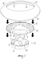
- the reference numeral 1 designates a luminaire constituted by a backing element, designated by the reference numeral 2, which is preferably made of metal and has a box-like shape so as to form a base 3 from which an annular rim 4 protrudes perimetrically.
- the backing element can be wall- or ceiling-mounted, either in contact therewith or suspended therefrom.
- Suitable means for removable connection to a blown-glass diffuser 5 are associable at the annular rim 4 of the backing element 2; said means are constituted for example by suitable screws or springs, whose tip affects a suitable first groove 6 formed at the end of the diffuser that is adjacent to the base and to the backing element 2.
- the backing element 2 constitutes a support for a lighting fixture 7 constituted by a light bulb 8 which is associated with a lamp holder 9, the lamp holder 9 being in turn rigidly coupled, for example by means of a suitable bracket 10, to the base 3 of the backing element 2.
- the luminaire is also constituted by at least one first decorative element 11 which is advantageously constituted by an annular body, made of metal or plastics, provided with an inner perimetric rim 12 which is advantageously curved and whose diameter is slightly larger than the maximum diameter of the blown-glass diffuser 5.
- the inner perimetric rim 12 can thus be detachably associated, by snap action, at a suitable seat formed perimetrically with respect to the blown-glass diffuser 5.
- the seat is advantageously constituted by a second annular guide 13 which allows the snap coupling of the inner perimetric rim 12 of the first decorative element 11.
- the first decorative element is therefore preferably frustum-shaped, so as to form a wall 14 suitable to conceal the underlying backing element 2 from the user's sight.
- the outer perimetric rim 15 of the first decorative element can be arranged adjacent or not to the wall and ceiling or on a level which is lower than, equal to, or higher than the plane of arrangement of the base 3 of said backing element 2, according to the specific aesthetic and application requirements of the luminaire.
- the present invention has achieved the intended aim and objects, a luminaire having been provided in which the first decorative element is quickly and easily associable with the blown-glass diffuser, the application being achievable directly by the end user, thus not requiring any additional treatment during the manufacture of the components.
- the configuration of the blown-glass diffuser can be of course the most suitable but is in any case suitable to conceal from view the backing element once the luminaire has been assembled.
- the easy and quick detachability of the first decorative element 11 also allows the user to choose and/or change the configuration and/or the coloring of the decorative element, for example according to the type of interior decoration of the room or to the color of the wall or ceiling, or to perform replacement in case of accidental breakage of the decorative element.
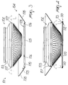
- the reference numeral 101 designates a luminaire constituted by a backing element, not shown, which can be wall- or ceiling-mounted, is preferably made of metal, and has a box-like configuration so as to form a base from which an annular rim protrudes; suitable means, not shown, for detachable connection to a blown-glass diffuser 102 are associable at said rim and are constituted for example by suitable screws the tip whereof affects a suitable first seat which is constituted by a first annular groove 103 formed at the end of the diffuser that is adjacent to the base of the backing element.
- the backing element constitutes a support for a lighting fixture, not shown, such as a light bulb associated with a lamp holder, which is in turn rigidly coupled, for example by a suitable bracket, to the base of the backing element.
- the luminaire is also constituted by a first decorative element 104, which is advantageously constituted by an annular body made of metal or plastics and having, at one end, an inner perimetric rim 105 which is advantageously curved and whose diameter is slightly larger than the maximum diameter of the blown-glass diffuser 102.
- Two or more raised portions 106 protrude towards the diffuser from the inner perimetric rim 105 and are shaped complementarily to a second seat which is constituted by a second annular groove 107 formed perimetrically with respect to the blown-glass diffuser 102 and allowing the snap coupling of the inner perimetric rim 5 of the first decorative element 104.
- the decorative element is therefore preferably frustum-shaped, so as to form a side wall 108 which is suitable to conceal the underlying backing element from the user's sight.
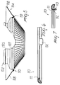
- Two or more notches 109 are also formed at the inner perimetric rim 105 and constitute grip means for a second decorative element 110.
- the decorative element is substantially constituted by a ring whose diameter is approximately equal to the diameter of the inner perimetric rim 105 of the first decorative element 104.
- Suitable tabs 112 spaced like the notches 109, further protrude towards the blown-glass diffuser 102 from the inner perimetric rim 111 of the second decorative element 10.
- a suitable tooth 113 is provided at the end of said tabs 112 and fits by snap action at the notches 109.
- the second decorative element 110 is arranged at the region for connecting the first decorative element 4 to the blown-glass diffuser 102.
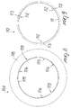
- the second decorative element 110 is constituted by a ring whose diameter is approximately equal to the diameter of the outer perimetric rim 114 of the element 102 at the second annular groove 107.
- Tabs 112 protrude towards the diffuser 102 from the inner perimetric rim 111 of the second element 110; a tooth 113 is formed at the ends of said tabs and enters by snap action the second annular groove 107.
- the shape of the blown-glass diffuser and the shape of the first and second decorative elements can of course also be the most suitable, allowing in any case to conceal the backing element from sight, once the luminaire 101 has been assembled, as well as the region that connects the first and second decorative elements.
- the easy and quick detachability of the second element 110 allows the user to choose and/or change the configuration and/or coloring of the second decorative element, for example according to the type of interior decoration of the room or to the color of the wall or ceiling, or to perform replacement in case of accidental breakage of said decorative element.
Landscapes
- Engineering & Computer Science (AREA)
- General Engineering & Computer Science (AREA)
- Non-Portable Lighting Devices Or Systems Thereof (AREA)
Applications Claiming Priority (4)
| Application Number | Priority Date | Filing Date | Title |
|---|---|---|---|
| ITTV970004U | 1997-01-24 | ||
| IT97TV000004 IT243072Y1 (it) | 1997-01-24 | 1997-01-24 | Struttura di apparecchio d'illuminazione con diffusore in vetrosoffiato |
| IT97TV000022 IT243088Y1 (it) | 1997-05-26 | 1997-05-26 | Struttura di apparecchio di illuminazione con diffusore in vetrosoffiato |
| ITTV970022U | 1997-05-26 |
Publications (2)
| Publication Number | Publication Date |
|---|---|
| EP0855553A2 true EP0855553A2 (fr) | 1998-07-29 |
| EP0855553A3 EP0855553A3 (fr) | 2000-02-23 |
Family
ID=26332463
Family Applications (1)
| Application Number | Title | Priority Date | Filing Date |
|---|---|---|---|
| EP98100986A Withdrawn EP0855553A3 (fr) | 1997-01-24 | 1998-01-21 | Luminaire avec diffuseur de verre soufflé |
Country Status (1)
| Country | Link |
|---|---|
| EP (1) | EP0855553A3 (fr) |
Cited By (1)
| Publication number | Priority date | Publication date | Assignee | Title |
|---|---|---|---|---|
| EP2020563A1 (fr) * | 2007-08-02 | 2009-02-04 | Hartmut S. Engel | Luminaire |
Family Cites Families (4)
| Publication number | Priority date | Publication date | Assignee | Title |
|---|---|---|---|---|
| DE1134161B (de) * | 1961-01-18 | 1962-08-02 | Hanns Willeke | Glockenleuchte mit duennwandigen, nach dem Blasverfahren hergestellten Schirmteilen aus thermoplastischem organischem Kunststoff |
| GB1359325A (en) * | 1972-05-24 | 1974-07-10 | Merchant Adventurers Ltd | Lighting units |
| JP2719997B2 (ja) * | 1992-08-26 | 1998-02-25 | 東芝機器株式会社 | 照明器具 |
| FR2740201B1 (fr) * | 1995-10-24 | 1997-12-19 | Ebenoid L | Dispositif d'eclairage a collerette de protection |
-
1998
- 1998-01-21 EP EP98100986A patent/EP0855553A3/fr not_active Withdrawn
Non-Patent Citations (1)
| Title |
|---|
| None |
Cited By (1)
| Publication number | Priority date | Publication date | Assignee | Title |
|---|---|---|---|---|
| EP2020563A1 (fr) * | 2007-08-02 | 2009-02-04 | Hartmut S. Engel | Luminaire |
Also Published As
| Publication number | Publication date |
|---|---|
| EP0855553A3 (fr) | 2000-02-23 |
Similar Documents
| Publication | Publication Date | Title |
|---|---|---|
| CA2482610C (fr) | Luminaires decoratifs | |
| US4217629A (en) | Corner lighting assembly | |
| US4479173A (en) | Lighted instrument assembly | |
| US4739454A (en) | Adjustable display light | |
| USD379550S (en) | Decorative diffuser globe for enclosing a light bulb | |
| US4310875A (en) | Universally adjustable lamp fixture | |
| US7370990B2 (en) | Equipment for a change of rotary gobos | |
| JP3131737B2 (ja) | 装飾用照明装置 | |
| CN103939857A (zh) | 可更换饰件的灯具 | |
| USD413580S (en) | Combined remote control and cradle assembly for a ceiling fan and light fixture | |
| US7086759B2 (en) | Decorative lamp | |
| EP0855553A2 (fr) | Luminaire avec diffuseur de verre soufflé | |
| US20020192077A1 (en) | Ceiling fan with light assembly | |
| US6814471B1 (en) | Adapter for decorative lighting fixture | |
| CN212565600U (zh) | 灯具角度可调组件及带有该组件的嵌入式转向灯 | |
| JP2000173310A (ja) | 照明器具 | |
| JP2004087160A (ja) | 投影型照明装置 | |
| KR200482638Y1 (ko) | 조명거울 | |
| US3235722A (en) | Illuminating ornament | |
| US7946736B1 (en) | Cover for recessed down-light | |
| US2022264A (en) | Lighting fixture | |
| KR20190017831A (ko) | 엘이디조명등의 장식테 조립구조 | |
| CN210219658U (zh) | 一种装饰灯 | |
| KR200281712Y1 (ko) | 간접조명용 할로겐조명등 | |
| KR200308937Y1 (ko) | 액자 및 화장용 거울 |
Legal Events
| Date | Code | Title | Description |
|---|---|---|---|
| PUAI | Public reference made under article 153(3) epc to a published international application that has entered the european phase |
Free format text: ORIGINAL CODE: 0009012 |
|
| AK | Designated contracting states |
Kind code of ref document: A2 Designated state(s): AT BE CH DE DK ES FI FR GB GR IE IT LI LU MC NL PT SE |
|
| AX | Request for extension of the european patent |
Free format text: AL;LT;LV;MK;RO;SI |
|
| PUAL | Search report despatched |
Free format text: ORIGINAL CODE: 0009013 |
|
| AK | Designated contracting states |
Kind code of ref document: A3 Designated state(s): AT BE CH DE DK ES FI FR GB GR IE IT LI LU MC NL PT SE |
|
| AX | Request for extension of the european patent |
Free format text: AL;LT;LV;MK;RO;SI |
|
| STAA | Information on the status of an ep patent application or granted ep patent |
Free format text: STATUS: THE APPLICATION HAS BEEN WITHDRAWN |
|
| 18W | Application withdrawn |
Withdrawal date: 20000531 |