EP0855555A1 - Appareil pour la production rapide de la vapeur pour fers à repasser ou nettoyeurs à vapeur - Google Patents
Appareil pour la production rapide de la vapeur pour fers à repasser ou nettoyeurs à vapeur Download PDFInfo
- Publication number
- EP0855555A1 EP0855555A1 EP97830015A EP97830015A EP0855555A1 EP 0855555 A1 EP0855555 A1 EP 0855555A1 EP 97830015 A EP97830015 A EP 97830015A EP 97830015 A EP97830015 A EP 97830015A EP 0855555 A1 EP0855555 A1 EP 0855555A1
- Authority
- EP
- European Patent Office
- Prior art keywords
- boiler
- steam
- moving member
- water
- supplying
- Prior art date
- Legal status (The legal status is an assumption and is not a legal conclusion. Google has not performed a legal analysis and makes no representation as to the accuracy of the status listed.)
- Withdrawn
Links
- 235000000396 iron Nutrition 0.000 title description 2
- 238000004519 manufacturing process Methods 0.000 title description 2
- XLYOFNOQVPJJNP-UHFFFAOYSA-N water Substances O XLYOFNOQVPJJNP-UHFFFAOYSA-N 0.000 claims abstract description 31
- XEEYBQQBJWHFJM-UHFFFAOYSA-N Iron Chemical compound [Fe] XEEYBQQBJWHFJM-UHFFFAOYSA-N 0.000 claims abstract description 18
- 229910052742 iron Inorganic materials 0.000 claims abstract description 9
- 238000009835 boiling Methods 0.000 claims description 6
- 238000006073 displacement reaction Methods 0.000 claims description 4
- 238000010409 ironing Methods 0.000 description 2
- 230000010355 oscillation Effects 0.000 description 2
- 230000006835 compression Effects 0.000 description 1
- 238000007906 compression Methods 0.000 description 1
- 230000007423 decrease Effects 0.000 description 1
- 238000010586 diagram Methods 0.000 description 1
- 238000001704 evaporation Methods 0.000 description 1
- 230000008020 evaporation Effects 0.000 description 1
- 230000000737 periodic effect Effects 0.000 description 1
- 230000000284 resting effect Effects 0.000 description 1
Images
Classifications
-
- D—TEXTILES; PAPER
- D06—TREATMENT OF TEXTILES OR THE LIKE; LAUNDERING; FLEXIBLE MATERIALS NOT OTHERWISE PROVIDED FOR
- D06F—LAUNDERING, DRYING, IRONING, PRESSING OR FOLDING TEXTILE ARTICLES
- D06F75/00—Hand irons
- D06F75/08—Hand irons internally heated by electricity
- D06F75/10—Hand irons internally heated by electricity with means for supplying steam to the article being ironed
- D06F75/12—Hand irons internally heated by electricity with means for supplying steam to the article being ironed the steam being produced from water supplied to the iron from an external source
-
- F—MECHANICAL ENGINEERING; LIGHTING; HEATING; WEAPONS; BLASTING
- F22—STEAM GENERATION
- F22B—METHODS OF STEAM GENERATION; STEAM BOILERS
- F22B1/00—Methods of steam generation characterised by form of heating method
- F22B1/28—Methods of steam generation characterised by form of heating method in boilers heated electrically
- F22B1/284—Methods of steam generation characterised by form of heating method in boilers heated electrically with water in reservoirs
- F22B1/285—Methods of steam generation characterised by form of heating method in boilers heated electrically with water in reservoirs the water being fed by a pump to the reservoirs
Definitions
- the currently known boilers for producing steam to be supplied to irons consist of a heated container with a cap for topping up the water content when the quantity of water previously introduced inside the boiler is about to run out. This results, among other things, in:
- the apparatus with a boiler for producing steam intended for an iron, a steam cleaner or the like substantially comprises a moving member on which the boiler is mounted and which is raised and lowered depending on the variation in weight of the boiling water inside the boiler, and a control system which is based on the displacements of said moving member and which controls the supply of limited quantities of water to the boiler.
- the said moving member is supported by at least one resilient element and more particularly said moving member may be hinged on a horizontal axis and supported by at least one spring at a distance from said axis.
- the apparatus comprises an electric pump for supplying the water to the boiler and a switch, in particular a microswitch, which is actuated by the displacement of the said moving member and which operates the said electric pump.
- both the pipe supplying the steam from the boiler and the delivery pipe of the pump for supplying the water to the boiler have a deformable section; advantageously said deformable sections extend adjacent and parallel to the said hinging axis of the moving member.
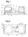
- a fixed tank 1 is connected by means of a draw-off pipe 2 to an electric pump 3 which forces the water through a supply pipe 4 into the boiler 5 heated by the resistor 6.
- the boiler is mounted on a moving member 7 which is joined to a surface 8 - on which the tank 1 is situated - by means of a hinge 9 with a horizontal axis; said moving member 7 is supported by a spring 10.
- the moving member 7 compresses the spring 10 on which it rests and is thus lowered until it acts on a switch 11, which interrupts operation of the pump 3, interrupting the introduction of water into the boiler.
- the temperature of the boiler is controlled by a thermostat 14.
- the boiler is provided with at least one pressure-regulating valve 13 which will allow the steam to escape from the boiler in the event of excessive pressure inside the boiler itself.
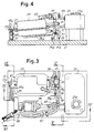
- the water tank 23 is located in a fixed manner on a base 21; a lid 23A allows periodic filling of this tank 23, independently of the frequency with which the boiler is supplied for generation of the steam.
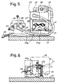
- a moving member 27 which comprises in particular also the boiler 29; at a distance from the hinging axis 25, this moving member 27 rests on a spring 31 so that, with the variation in the load of the moving member 27 comprising the boiler 29, it is possible to obtain a variation in the compression of the spring and hence gradual raising of the moving member itself as water inside the boiler 29 is used up for the production of steam supplied to the iron.
- the pipe 33 denotes the pipe for conveying the steam from the boiler 29 to the iron (not shown); said pipe 33 is flexible and the section 33A thereof extends in the vicinity of the hinging axis 25 and parallel to this oscillation axis so that the movement of the moving member 27 about the axis 25 produces only a very small torsional deformation of the said section 33A of the pipe 33.
- 35 denotes a solenoid valve for effecting removal of the steam from the boiler; said solenoid valve 35 is controlled by a pushbutton or other operating member which is present in the iron; thus the user is able to request a supply of steam, as required, by operating said pushbutton or the like using the same hand with which the iron is gripped.
- the water is supplied from the tank 23 to the boiler 29 via a pipe 37 which reaches an electric pump 39.
- a delivery pipe 41 extends from the pump 39, said delivery pipe being flexible and extending with a section 41A in the vicinity of and approximately parallel to the axis of rotation 25, so that this pipe 41 also undergoes a very limited degree of torsional deformation with the movement of the moving member 27 of the boiler 29 about the axis 25.
- 43 denotes a return pipe from the pump 39 towards the tank 23, allowing the flowback of pumped water exceeding the predefined throughput for supply of the boiler itself.
- a bracket 27A forming part of the moving member 27 and positioned at a distance from the hinging axis 25, is used for resting on the spring 31 and for acting on the actuating arm 45A of a microswitch 45 which controls the motor of the electric pump 39.
- FIG. 29A denotes the heat source - for example an electric resistor - which serves to generate the steam inside the boiler 29.
- This heat generator is controlled by a pressure switch and/or a thermostat, as mentioned above.
- the moving member 27 As the quantity of boiling water contained in the boiler is reduced owing to the generation of the steam supplied (via 33 and 33A) to the iron, the moving member 27 is gradually raised by the spring 31 until raising of the moving member 27 is such that it triggers, via the microswitch 45, operation of the pump 39 so as to allow a desired and limited quantity of cold water to be introduced from the tank to the boiler 29; this quantity of pumped water is limited with respect to the residual quantity of water which is already boiling, so that there is practically no variation in the capacity of the boiler to deliver steam to the iron.
Landscapes
- Engineering & Computer Science (AREA)
- Health & Medical Sciences (AREA)
- Public Health (AREA)
- Textile Engineering (AREA)
- Life Sciences & Earth Sciences (AREA)
- Sustainable Development (AREA)
- Sustainable Energy (AREA)
- Physics & Mathematics (AREA)
- Thermal Sciences (AREA)
- Mechanical Engineering (AREA)
- General Engineering & Computer Science (AREA)
- Irons (AREA)
Priority Applications (1)
| Application Number | Priority Date | Filing Date | Title |
|---|---|---|---|
| EP97830015A EP0855555A1 (fr) | 1997-01-23 | 1997-01-23 | Appareil pour la production rapide de la vapeur pour fers à repasser ou nettoyeurs à vapeur |
Applications Claiming Priority (1)
| Application Number | Priority Date | Filing Date | Title |
|---|---|---|---|
| EP97830015A EP0855555A1 (fr) | 1997-01-23 | 1997-01-23 | Appareil pour la production rapide de la vapeur pour fers à repasser ou nettoyeurs à vapeur |
Publications (1)
| Publication Number | Publication Date |
|---|---|
| EP0855555A1 true EP0855555A1 (fr) | 1998-07-29 |
Family
ID=8230558
Family Applications (1)
| Application Number | Title | Priority Date | Filing Date |
|---|---|---|---|
| EP97830015A Withdrawn EP0855555A1 (fr) | 1997-01-23 | 1997-01-23 | Appareil pour la production rapide de la vapeur pour fers à repasser ou nettoyeurs à vapeur |
Country Status (1)
| Country | Link |
|---|---|
| EP (1) | EP0855555A1 (fr) |
Cited By (4)
| Publication number | Priority date | Publication date | Assignee | Title |
|---|---|---|---|---|
| WO2006067722A3 (fr) * | 2004-12-22 | 2007-02-08 | Koninkl Philips Electronics Nv | Chaudiere utilisee dans un dispositif generateur de vapeur |
| CN102121695A (zh) * | 2011-01-27 | 2011-07-13 | 浙江华光电器集团有限公司 | 一种蒸汽发生器自助补水装置 |
| CN105229376A (zh) * | 2013-05-14 | 2016-01-06 | 阿尔弗雷德·凯驰两合公司 | 蒸汽发生器 |
| EP1484961B2 (fr) † | 2002-03-15 | 2016-09-07 | DeLaval Holding AB | Procede et dispositif pour ferme laitiere |
Citations (4)
| Publication number | Priority date | Publication date | Assignee | Title |
|---|---|---|---|---|
| GB477870A (en) * | 1936-03-24 | 1938-01-07 | Fernan Oscar Conill | Improvements in or relating to apparatus for producing a constant supply of steam or vapour |
| FR1525214A (fr) * | 1967-04-03 | 1968-05-17 | Thomson Houston Comp Francaise | Perfectionnements aux générateurs de vapeur |
| EP0239822A2 (fr) * | 1986-04-04 | 1987-10-07 | Degussa Aktiengesellschaft | Appareil pour la production de vapeur et d'eau chaude |
| EP0438112A2 (fr) * | 1990-01-17 | 1991-07-24 | Metalnova di Dario Pietro e Maurilio & C. - S.A.S. | Fer à repasser À vapeur |
-
1997
- 1997-01-23 EP EP97830015A patent/EP0855555A1/fr not_active Withdrawn
Patent Citations (4)
| Publication number | Priority date | Publication date | Assignee | Title |
|---|---|---|---|---|
| GB477870A (en) * | 1936-03-24 | 1938-01-07 | Fernan Oscar Conill | Improvements in or relating to apparatus for producing a constant supply of steam or vapour |
| FR1525214A (fr) * | 1967-04-03 | 1968-05-17 | Thomson Houston Comp Francaise | Perfectionnements aux générateurs de vapeur |
| EP0239822A2 (fr) * | 1986-04-04 | 1987-10-07 | Degussa Aktiengesellschaft | Appareil pour la production de vapeur et d'eau chaude |
| EP0438112A2 (fr) * | 1990-01-17 | 1991-07-24 | Metalnova di Dario Pietro e Maurilio & C. - S.A.S. | Fer à repasser À vapeur |
Cited By (7)
| Publication number | Priority date | Publication date | Assignee | Title |
|---|---|---|---|---|
| EP1484961B2 (fr) † | 2002-03-15 | 2016-09-07 | DeLaval Holding AB | Procede et dispositif pour ferme laitiere |
| WO2006067722A3 (fr) * | 2004-12-22 | 2007-02-08 | Koninkl Philips Electronics Nv | Chaudiere utilisee dans un dispositif generateur de vapeur |
| CN100590354C (zh) * | 2004-12-22 | 2010-02-17 | 皇家飞利浦电子股份有限公司 | 在蒸汽产生设备中使用的汽锅 |
| US7920778B2 (en) | 2004-12-22 | 2011-04-05 | Koninklijke Philips Electronics N.V. | Boiler for use in a steam generating device |
| CN102121695A (zh) * | 2011-01-27 | 2011-07-13 | 浙江华光电器集团有限公司 | 一种蒸汽发生器自助补水装置 |
| CN105229376A (zh) * | 2013-05-14 | 2016-01-06 | 阿尔弗雷德·凯驰两合公司 | 蒸汽发生器 |
| CN105229376B (zh) * | 2013-05-14 | 2017-04-19 | 阿尔弗雷德·凯驰两合公司 | 蒸汽发生器 |
Similar Documents
| Publication | Publication Date | Title |
|---|---|---|
| EP0821096B1 (fr) | Générateur de vapeur pour fers à repasser ou similaire | |
| US8402597B2 (en) | Steam appliance with motion switch | |
| EP1980659B1 (fr) | Générateur de vapeur pour une machine à laver | |
| AU2007208543B2 (en) | Steam generator and washing machine therewith | |
| KR100540749B1 (ko) | 드럼세탁기용 증기발생장치 | |
| JP4063675B2 (ja) | スチーマシステム | |
| US6561079B1 (en) | Steam generating device for heating and/or frothing liquids | |
| EP0659381B1 (fr) | Procédé opérationnel pour machine à laver la vaisselle | |
| US4575615A (en) | Hot water supplying device | |
| EP1221570A2 (fr) | Générateur de vapeur avec système automatique de chargement d'eau | |
| EP2031115A1 (fr) | Appareil de traitement de tissus doté d'un dispositif d'anti-retour de vapeur | |
| EP0333728B1 (fr) | Generateur de vapeur avec pression auto-regulee destine en particulier a des petites installations electriques domestiques | |
| EP3266926A1 (fr) | Un procédé de génération de vapeur et un système de génération de vapeur | |
| EP1831602B1 (fr) | Chaudiere utilisee dans un dispositif generateur de vapeur | |
| EP2031117A1 (fr) | Appareil de traitement de tissus doté d'un dispositif de reflux de vapeur | |
| EP0299343A1 (fr) | Elément de chauffage pour appareils électriques domestiques | |
| EP1774224B1 (fr) | Dispositif a vapeur destine particulierement a des appareils domestiques electriques | |
| EP0478508A1 (fr) | Générateur de vapeur à usage domestique | |
| RU2442849C2 (ru) | Способ регулирования паровой установки в бытовом устройстве | |
| EP0958777B1 (fr) | Régulateur de niveau d'eau pour une machine à laver la vaisselle | |
| KR100704337B1 (ko) | 스팀발생을 위한 재가열 히팅장치 | |
| CN222417388U (zh) | 用于产生蒸汽的家用电器 | |
| WO2020136248A1 (fr) | Lave-linge à fonction de lavage à la vapeur | |
| GB2286179A (en) | Water storage tank arrangement | |
| CA1274569A (fr) | Generateur de vapeur utilitaire a autoregulation de la pression, plus particulierement pour petits appareils menagers electriques |
Legal Events
| Date | Code | Title | Description |
|---|---|---|---|
| PUAI | Public reference made under article 153(3) epc to a published international application that has entered the european phase |
Free format text: ORIGINAL CODE: 0009012 |
|
| AK | Designated contracting states |
Kind code of ref document: A1 Designated state(s): CH DE ES FR GB IT LI |
|
| AX | Request for extension of the european patent |
Free format text: AL;LT;LV;RO;SI |
|
| 17P | Request for examination filed |
Effective date: 19981221 |
|
| AKX | Designation fees paid |
Free format text: CH DE ES FR GB IT LI |
|
| RBV | Designated contracting states (corrected) |
Designated state(s): CH DE ES FR GB IT LI |
|
| 17Q | First examination report despatched |
Effective date: 20000204 |
|
| STAA | Information on the status of an ep patent application or granted ep patent |
Free format text: STATUS: THE APPLICATION HAS BEEN WITHDRAWN |
|
| 18W | Application withdrawn |
Withdrawal date: 20000529 |