EP0855557B1 - Circuit de commande d'une soupape à gaz avec contrÔle de l'alimentation d'air comburant - Google Patents
Circuit de commande d'une soupape à gaz avec contrÔle de l'alimentation d'air comburant Download PDFInfo
- Publication number
- EP0855557B1 EP0855557B1 EP97100909A EP97100909A EP0855557B1 EP 0855557 B1 EP0855557 B1 EP 0855557B1 EP 97100909 A EP97100909 A EP 97100909A EP 97100909 A EP97100909 A EP 97100909A EP 0855557 B1 EP0855557 B1 EP 0855557B1
- Authority
- EP
- European Patent Office
- Prior art keywords
- relay
- control circuit
- charging
- rectifier
- circuit according
- Prior art date
- Legal status (The legal status is an assumption and is not a legal conclusion. Google has not performed a legal analysis and makes no representation as to the accuracy of the status listed.)
- Expired - Lifetime
Links
Images
Classifications
-
- F—MECHANICAL ENGINEERING; LIGHTING; HEATING; WEAPONS; BLASTING
- F23—COMBUSTION APPARATUS; COMBUSTION PROCESSES
- F23N—REGULATING OR CONTROLLING COMBUSTION
- F23N5/00—Systems for controlling combustion
- F23N5/20—Systems for controlling combustion with a time program acting through electrical means, e.g. using time-delay relays
- F23N5/203—Systems for controlling combustion with a time program acting through electrical means, e.g. using time-delay relays using electronic means
-
- F—MECHANICAL ENGINEERING; LIGHTING; HEATING; WEAPONS; BLASTING
- F23—COMBUSTION APPARATUS; COMBUSTION PROCESSES
- F23N—REGULATING OR CONTROLLING COMBUSTION
- F23N5/00—Systems for controlling combustion
- F23N5/24—Preventing development of abnormal or undesired conditions, i.e. safety arrangements
- F23N5/242—Preventing development of abnormal or undesired conditions, i.e. safety arrangements using electronic means
-
- F—MECHANICAL ENGINEERING; LIGHTING; HEATING; WEAPONS; BLASTING
- F23—COMBUSTION APPARATUS; COMBUSTION PROCESSES
- F23N—REGULATING OR CONTROLLING COMBUSTION
- F23N5/00—Systems for controlling combustion
- F23N5/18—Systems for controlling combustion using detectors sensitive to rate of flow of air or fuel
- F23N2005/181—Systems for controlling combustion using detectors sensitive to rate of flow of air or fuel using detectors sensitive to rate of flow of air
- F23N2005/182—Air flow switch
-
- F—MECHANICAL ENGINEERING; LIGHTING; HEATING; WEAPONS; BLASTING
- F23—COMBUSTION APPARATUS; COMBUSTION PROCESSES
- F23N—REGULATING OR CONTROLLING COMBUSTION
- F23N2223/00—Signal processing; Details thereof
- F23N2223/22—Timing network
- F23N2223/26—Timing network with capacitors
-
- F—MECHANICAL ENGINEERING; LIGHTING; HEATING; WEAPONS; BLASTING
- F23—COMBUSTION APPARATUS; COMBUSTION PROCESSES
- F23N—REGULATING OR CONTROLLING COMBUSTION
- F23N2223/00—Signal processing; Details thereof
- F23N2223/22—Timing network
- F23N2223/28—Timing network with more than one timing element
-
- F—MECHANICAL ENGINEERING; LIGHTING; HEATING; WEAPONS; BLASTING
- F23—COMBUSTION APPARATUS; COMBUSTION PROCESSES
- F23N—REGULATING OR CONTROLLING COMBUSTION
- F23N2233/00—Ventilators
- F23N2233/06—Ventilators at the air intake
-
- F—MECHANICAL ENGINEERING; LIGHTING; HEATING; WEAPONS; BLASTING
- F23—COMBUSTION APPARATUS; COMBUSTION PROCESSES
- F23N—REGULATING OR CONTROLLING COMBUSTION
- F23N2235/00—Valves, nozzles or pumps
- F23N2235/12—Fuel valves
- F23N2235/14—Fuel valves electromagnetically operated
Definitions
- the invention relates to a control circuit for a gas valve with simultaneous monitoring the combustion air supply according to the preamble of claim 1, as from EP-0 698 767 B1 is known.
- the invention is particularly based on the self-monitoring of the Flow switch for the combustion air supply directed to ensure that this in the absence of air supply does not pretend the presence of air flow by being Make contact already at the beginning of the burner cycle, i.e. before the fan is switched on, closed is.
- the excitation current for a the is in EP 0 698 767 Gas valve switching relay supplied by a charging capacitor, which via a Normally open contact of the flow switch designed as a switch is charged.
- the present invention simplifies the control circuit mentioned achieved by self-monitoring no longer the presence of a flow switch in the form of a switch, but the flow switch as easier Working contact can be formed, which in the presence of a predetermined Minimum flow closes. This also allows the flow switch to be used Train electronic switch, which in the presence of air flow Excitation circuit for the gas valve closes and interrupts in the absence of air flow.
- the invention is characterized in claim 1. The fact that the supply terminal of Loading resistance when the flow switch is closed via this with the second AC supply line is connected directly or, for example, via a diode, cannot at the beginning of the burner cycle when the flow switch is incorrectly closed Charging of the charging capacitor take place because of this via the flow switch is short-circuited. This also creates an inrush current for the relay prevented.
- Advantageous embodiments of the invention result from the subclaims.
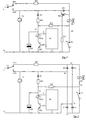
- the relay RY02 has a changeover contact Normally open contact NO2 and normally closed contact NC2, while the contact arm C2 on one Mains AC voltage line L is.
- the relay RY02 is equipped with an electronic switch, e.g. a transistor Q02, connected in series, the control electrode of the output A a control electronics CE is connected.
- a holding circuit with a diode D1 and A resistor R02 leads from the NO2 normally open contact to the excitation winding RY02 and via the electronic switch Q02 to the other mains voltage line N.
- the Series connection of relay RY02 and electronic switch Q02 is a charging capacitor C05 connected in parallel, its charging resistor R05 via the field winding of the gas valve PV and a series resistor R01 and the normally closed contact NC2 of the relay switch with the Supply line L is connected.
- the input E of the control electronics CE is to the assignment of the charging capacitor C05 facing away from the ground potential N, see that this control electronics CE the electronic switch Q02 by a signal on their Output A switches through as soon as the charging voltage at input E reaches a predetermined value Threshold exceeded.
- the charging resistor R05 and the series resistor R01 are like this dimensioned that of these two resistors and the field winding of the gas valve PV flowing charging current to the capacitor C05 is not sufficient to open the gas valve PV.
- connection point P1 of resistor R02, resistor R05, capacitor C05 and relay RY02 at input E of control electronics CE is the connection point P1 facing away from the charging resistor R05 in Figures 1 and 2 to the Connection line P2 connected between valve PV and flow switch PS.
- a charging circuit is created for the charging capacitor C05 the line L via the relay contact C2 / NC2, the resistor R01, the valve winding PV and the charging resistor R05.
- the negative half wave is over the Series connection of diode D11 and blower motor FA bypassed capacitor C05, because the resistance value of resistor R1 (e.g. 68 kOhm) is much higher than that Fan impedance (approximately 200 ohms).
- the thyristor TH1 is blocked because its cathode k via the fan winding FA is practically at the same potential as its Control electrode c.
- the flow switch PS would already be closed due to some fault Start of the burner cycle, i.e. closed before the fan FA started, the would called positive half-wave also short-circuited via the flow switch PS and the Capacitor C05 could not be charged. In this way the Functionality of the flow switch PS checked before each burner cycle.
- the flow switch PS detects a sufficient air flow, it closes its Contact C / NO.
- the flow switch PS detects a sufficient air flow, it closes its Contact C / NO.
- the flow switch PS flows to the other supply line N, generates the negative half-wave via the resistor R11 on the control electrode c des Thyristor TH1 a positive control current, so that the thyristor TH1 turns on and the Current path also for the negative half wave of the AC mains voltage via the valve winding PV closes.
- the circuit is thus in the normal operating state, in which the Fan motor FA is running and the gas valve PV is open. Motor FA and valve PV is closed by switching off the supply voltage to the Terminals L and N.
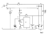
- a gas valve PV which has a Rectifier bridge circuit D11, D12, D13, D14 is excited with direct current. This is the make contact NO2 of the relay RY02 to the one input E1 and the line N to the other input E2 of the rectifier bridge connected.
- the valve PV and the Flow switches PS are in turn connected in series and here to the two outputs A1 and A2 of the rectifier bridge connected.
- the capacitor C05 is charged in the same way as in the previously described embodiment, the positive Half wave flows via NC2, R01, PV, R05 and P1 to capacitor C05, while the negative Half wave on the line L via the diode D11 and the fan winding FA none Charging current arises because the resistance of resistor R1 (e.g. 68kOhm) is essential is higher than the fan impedance of about 200 ohms. This predominates, as in Embodiment according to Figure 1, the charging current from the positive half wave to the negative Charging current is considerable.
- resistor R1 e.g. 68kOhm
- the relay RY02 responds as soon as, as described above, the charging voltage at input E exceeds the threshold and the control electronics CE turns on the transistor Q02.
- the control electronics CE turns on the transistor Q02.
- the AC input voltage is then applied to the Inputs E1 and E2 of the rectifier bridge and on the fan FA.
- the flow switch PS closes and connects it Gas valve with outputs A1 and A2 of the rectifier bridge circuit. The valve opens and the system runs in normal operation.
- the flow switch PS is not at the exit, but at the entrance of the rectifier bridge, namely between the input E2 and the Ground line N.
- the rectifier bridge can only supply a DC excitation current for deliver the valve PV when the flow switch PS is closed.
- One of the rectifiers the bridge circuit is a controlled rectifier, e.g. a thyristor TH1, the Control electrode g via a resistor R11, similar to that in Figure 1, to the Supply line N (ground) is connected.
- a positive charging current flows from line L to charge capacitor C05 R01, PV, D14 and R05 to the capacitor.
- the thyristor TH1 is blocked because of its cathode k is practically at the same potential as its via the fan winding FA Control electrode g.
- the negative half wave is from D11 and FA as well as PS from Capacitor kept away because the resistance of resistor R1 (e.g. 68 kOhm) is significantly higher than the impedance of the fan of approximately 200 ohms.
- the relay RY02 switches when the charging voltage of the capacitor reaches the threshold determined by CE exceeds.
- the flow switch PS detects a sufficient air flow, it closes its Contact C / NO.
- diode D11, valve winding PV, the diode D14 and the flow switch PS flows to the other supply line N, generates the negative half-wave via the resistor R11 on the control electrode g des Thyristor TH1 a positive control current, so that the thyristor TH1 turns on.
- the holding current for the relay RY02 arrives as in the previous exemplary embodiments of NO2 via D1 and R02 Relay.
Landscapes
- Engineering & Computer Science (AREA)
- Chemical & Material Sciences (AREA)
- Combustion & Propulsion (AREA)
- Mechanical Engineering (AREA)
- General Engineering & Computer Science (AREA)
- Regulation And Control Of Combustion (AREA)
- Relay Circuits (AREA)
Claims (10)
- Circuit de commande, alimenté par du courant alternatif, pour une soupape électromagnétique à gaz, avec contrôle de l'alimentation en air de combustion, comportant:caractérisé en ce que la borne, située du côté opposé au condensateur de charge (C05), de la résistance de charge (R05) est reliée, par l'intermédiaire de l'interrupteur d'écoulement (PS) conçu sous la forme d'un contact de travail (C, NO), à l'autre conducteur d'alimentation en courant alternatif (N).a) un interrupteur d'écoulement (PS) destiné à contrôler l'alimentation en air;b) un relais (RY02) à contact inverseur;c) un condensateur de charge (C05) avec une résistance de charge (R05), fournissant le courant de déclenchement pour le relais, etd) un circuit de maintien (D1, R02) pour le relais, étant précisé que:e) la barre de commutation (C2) du contact inverseur est située sur l'un (L) des conducteurs d'alimentation en courant alternatif, le contact de travail (N02) assure l'alimentation du circuit de maintien et le contact de repos (NC2) est raccordé au condensateur de charge (C05) au travers de la résistance de charge (R05),
- Circuit de commande selon la revendication 1, caractérisé en ce quea) l'un des points de connexion du bobinage d'excitation de la soupape électromagnétique à gaz (PV) est raccordé, d'une part, au contact de repos (NC2) du relais (RY02), au travers d'une résistance (R01), et, d'autre part, au contact de travail (N02), au travers d'un premier redresseur (D11), etb) l'autre point de connexion de la soupape est relié, par l'intermédiaire de l'interrupteur d'écoulement (PS), à l'autre conducteur d'alimentation en courant alternatif (N).
- Circuit de commande selon la revendication 2, caractérisé en ce qu'un second redresseur (D14) est inséré dans le conducteur de jonction situé entre l'autre point de connexion de la soupape et l'autre conducteur d'alimentation en courant alternatif (N) (figures 2 et 3).
- Circuit de commande selon l'une des revendications 1 à 3, comportant un interrupteur électronique (Q02) monté en série avec le bobinage du relais (RY02), ce montage en série (RY02, Q02) étant monté en parallèle sur le condensateur de charge (C05), caractérisé en ce que la résistance de charge (R05), par sa borne de connexion située du côté opposé au point de jonction (P1) du condensateur de charge et du bobinage du relais, est raccordée au conducteur de jonction (P2) de la bobine d'excitation de la soupape (PV) et de l'interrupteur d'écoulement (PS) (figures 1 et 2).
- Circuit de commande selon la revendication 2 ou 4, caractérisé en ce que sur le premier redresseur (D11), est monté en parallèle un redresseur commandé (TH1) de polarité opposée, dont l'électrode de commande (c) est reliée, au travers d'une résistance (R11), à l'autre conducteur d'alimentation en courant alternatif (N) (figure 1).
- Circuit de commande selon l'une des revendications 2 à 4, pour une soupape électromagnétique à gaz (PV) excitée par du courant continu, caractérisé en ce qu'un montage en pont de redresseurs (D11, D12, D13, D14) est raccordé, par ses bornes d'entrée (E1, E2), au contact de travail (N02) du relais (RY02) et à l'autre conducteur d'alimentation en courant (N), tandis que ses bornes de sortie (A1, A2) sont situées aux bornes du montage en série du bobinage d'excitation de la soupape (PV) et de l'interrupteur d'écoulement (PS), et en ce que l'un des redresseurs (D11, D12, D13, D14) du pont est le premier redresseur (D11) (figure 2).
- Circuit de commande selon l'une des revendications 1 à 4, avec une soupape électromagnétique à gaz (PV) excitée par du courant continu, caractérisé en ce qu'un montage en pont de redresseurs (D11, D12, TH1, D14) est raccordé par sa première borne d'entrée (E1) au contact de travail (N02) du relais (RY02), par sa seconde borne d'entrée (E2), au travers de l'interrupteur d'écoulement (PS), à l'autre conducteur d'alimentation en courant (N) et, par ses bornes de sortie (A1, A2), au bobinage d'excitation de la soupape (PV) (figure 3).
- Circuit de commande selon la revendication 7, caractérisé en ce que l'un des redresseurs du montage en pont est conçu sous forme d'un redresseur pouvant être commandé (TH1) et son électrode de commande (g) est reliée, au travers d'une résistance (R11), à l'autre conducteur d'alimentation en courant (N).
- Circuit de commande selon l'une des revendications 1 à 8, caractérisé en ce que l'électrode de commande de l'interrupteur électronique (Q02) est située à la sortie (A) d'un dispositif électronique de commande (CE), dont l'entrée (E) est raccordée au point de jonction (P1) du condensateur de charge (C05) et du bobinage du relais (RY02).
- Circuit de commande selon l'une des revendications 1 à 9, caractérisé en ce que le ventilateur (FA) est inséré entre le contact de travail (N02) du relais (RY02) et l'autre conducteur d'alimentation en courant (N).
Priority Applications (4)
| Application Number | Priority Date | Filing Date | Title |
|---|---|---|---|
| DE59700550T DE59700550D1 (de) | 1997-01-22 | 1997-01-22 | Steuerschaltung für Gasventil mit Überwachung der Verbrennungsluftzufuhr |
| EP97100909A EP0855557B1 (fr) | 1997-01-22 | 1997-01-22 | Circuit de commande d'une soupape à gaz avec contrÔle de l'alimentation d'air comburant |
| SK8-98U SK2234U (sk) | 1997-01-22 | 1998-01-19 | Riadiaci obvod napájaný striedavým prúdom plynového magnetického ventilu s kontrolou privádzania spaľovacieho vzduchu |
| CZ19987590U CZ7416U1 (cs) | 1997-01-22 | 1998-01-22 | Řídící obvod |
Applications Claiming Priority (1)
| Application Number | Priority Date | Filing Date | Title |
|---|---|---|---|
| EP97100909A EP0855557B1 (fr) | 1997-01-22 | 1997-01-22 | Circuit de commande d'une soupape à gaz avec contrÔle de l'alimentation d'air comburant |
Publications (2)
| Publication Number | Publication Date |
|---|---|
| EP0855557A1 EP0855557A1 (fr) | 1998-07-29 |
| EP0855557B1 true EP0855557B1 (fr) | 1999-10-13 |
Family
ID=8226389
Family Applications (1)
| Application Number | Title | Priority Date | Filing Date |
|---|---|---|---|
| EP97100909A Expired - Lifetime EP0855557B1 (fr) | 1997-01-22 | 1997-01-22 | Circuit de commande d'une soupape à gaz avec contrÔle de l'alimentation d'air comburant |
Country Status (4)
| Country | Link |
|---|---|
| EP (1) | EP0855557B1 (fr) |
| CZ (1) | CZ7416U1 (fr) |
| DE (1) | DE59700550D1 (fr) |
| SK (1) | SK2234U (fr) |
Cited By (1)
| Publication number | Priority date | Publication date | Assignee | Title |
|---|---|---|---|---|
| EP1195558A1 (fr) | 2000-10-06 | 2002-04-10 | Honeywell B.V. | Circuit de commande |
Families Citing this family (2)
| Publication number | Priority date | Publication date | Assignee | Title |
|---|---|---|---|---|
| DE50000553D1 (de) * | 2000-02-11 | 2002-10-31 | Honeywell Bv | Steuerschaltung |
| PT1182402E (pt) * | 2000-08-25 | 2004-06-30 | Honeywell Bv | Circuito de comando |
Family Cites Families (4)
| Publication number | Priority date | Publication date | Assignee | Title |
|---|---|---|---|---|
| US4403942A (en) * | 1980-11-18 | 1983-09-13 | Carrier Corporation | Self-checking safety switch control circuit |
| US5074780A (en) * | 1988-09-01 | 1991-12-24 | Honeywell, Inc. | Control system for forced combustion air heating appliance |
| DE59102338D1 (de) * | 1990-10-10 | 1994-09-01 | Honeywell Bv | Luftstromüberwachungseinrichtung für Brenneranlagen. |
| EP0698767B1 (fr) * | 1994-08-24 | 1996-10-30 | Honeywell B.V. | Circuit de commande d'un brûleur à gaz avec contrÔle de l'alimentation d'air comburant |
-
1997
- 1997-01-22 EP EP97100909A patent/EP0855557B1/fr not_active Expired - Lifetime
- 1997-01-22 DE DE59700550T patent/DE59700550D1/de not_active Expired - Fee Related
-
1998
- 1998-01-19 SK SK8-98U patent/SK2234U/sk unknown
- 1998-01-22 CZ CZ19987590U patent/CZ7416U1/cs active Protection Beyond IP Right Term
Cited By (1)
| Publication number | Priority date | Publication date | Assignee | Title |
|---|---|---|---|---|
| EP1195558A1 (fr) | 2000-10-06 | 2002-04-10 | Honeywell B.V. | Circuit de commande |
Also Published As
| Publication number | Publication date |
|---|---|
| CZ7416U1 (cs) | 1998-06-01 |
| SK2234U (sk) | 1999-07-12 |
| DE59700550D1 (de) | 1999-11-18 |
| EP0855557A1 (fr) | 1998-07-29 |
Similar Documents
| Publication | Publication Date | Title |
|---|---|---|
| DE4129557C2 (de) | Stromversorgungsschaltung für eine Gasentladungslampe in einem Fahrzeug | |
| DE69312576T2 (de) | Anlassschaltung für einen Einphasen-Induktionsmotor | |
| DE60124760T2 (de) | Hybride elektrische schalteinrichtung | |
| DE2552666A1 (de) | Logische schaltung | |
| DE3130769C2 (de) | Erregerschaltung für einen Mikrowellenofen | |
| EP1125351B1 (fr) | Circuit de protection destine a un montage en serie compose d'etages de sortie a semi-conducteurs de puissance et d'un consommateur inductif | |
| EP0855557B1 (fr) | Circuit de commande d'une soupape à gaz avec contrÔle de l'alimentation d'air comburant | |
| DE1551954A1 (de) | Steuereinrichtung fuer eine Feuerungsanlage | |
| EP0615267B1 (fr) | Circuit de test des contacts d'interrupteur ou de relais | |
| DE3119794C2 (de) | Schutzschaltungsanordnung für einen phasenanschnittgesteuerten oder -geregelten Elektromotor | |
| EP0698767B1 (fr) | Circuit de commande d'un brûleur à gaz avec contrÔle de l'alimentation d'air comburant | |
| EP1843645A2 (fr) | Circuit pour lampes à décharge haute pression | |
| EP3742466B1 (fr) | Ensemble de circuit permettant de commuter de manière sécurisée un consommateur électrique selon une mesure de sécurité | |
| DE2809993A1 (de) | Flammenwaechterschaltung zur ueberwachung einer brennerflamme | |
| EP0440872B1 (fr) | Circuit d'allumage et de sécurité pour brûleur à gaz | |
| DE2727073C3 (de) | Verzögerungsschaltung für Zeitrelais | |
| DE2557691A1 (de) | Steuer- und ueberwachungsgeraet fuer einen oel- oder gasbrenner | |
| DE2809843A1 (de) | Steueranordnung fuer eine brennstoffzuendanlage | |
| DE2757276A1 (de) | Sicherheitsschaltung fuer temperaturgeregelte, mit wechselspannung betriebene elektrische heiz- oder waermegeraete | |
| EP3850652A1 (fr) | Module relais | |
| DE3411300C2 (de) | Elektronische Schaltungsanordnung für Feuerungsautomaten | |
| DE2429289A1 (de) | Brennersteuerung | |
| DE2645734C2 (de) | Kraftstoff-Versorgungseinrichtung für Brennkraftmaschinen | |
| DE1563572A1 (de) | Ausschaltvorrichtung mit einem die OEffnung eines kontrollierten Stromkreises steuernden Relais | |
| DE817621C (de) | Selbsttaetige, mit mindestens drei Schaltstufen versehene elektromagnetische Anlassschaltschuetzensteuerung |
Legal Events
| Date | Code | Title | Description |
|---|---|---|---|
| PUAI | Public reference made under article 153(3) epc to a published international application that has entered the european phase |
Free format text: ORIGINAL CODE: 0009012 |
|
| 17P | Request for examination filed |
Effective date: 19971117 |
|
| AK | Designated contracting states |
Kind code of ref document: A1 Designated state(s): DE FR GB IT NL |
|
| GRAG | Despatch of communication of intention to grant |
Free format text: ORIGINAL CODE: EPIDOS AGRA |
|
| 17Q | First examination report despatched |
Effective date: 19990210 |
|
| AKX | Designation fees paid |
Free format text: DE FR GB IT NL |
|
| RBV | Designated contracting states (corrected) |
Designated state(s): DE FR GB IT NL |
|
| GRAG | Despatch of communication of intention to grant |
Free format text: ORIGINAL CODE: EPIDOS AGRA |
|
| GRAH | Despatch of communication of intention to grant a patent |
Free format text: ORIGINAL CODE: EPIDOS IGRA |
|
| GRAH | Despatch of communication of intention to grant a patent |
Free format text: ORIGINAL CODE: EPIDOS IGRA |
|
| GRAA | (expected) grant |
Free format text: ORIGINAL CODE: 0009210 |
|
| AK | Designated contracting states |
Kind code of ref document: B1 Designated state(s): DE FR GB IT NL |
|
| REF | Corresponds to: |
Ref document number: 59700550 Country of ref document: DE Date of ref document: 19991118 |
|
| ET | Fr: translation filed | ||
| GBT | Gb: translation of ep patent filed (gb section 77(6)(a)/1977) |
Effective date: 19991111 |
|
| ITF | It: translation for a ep patent filed | ||
| PLBE | No opposition filed within time limit |
Free format text: ORIGINAL CODE: 0009261 |
|
| STAA | Information on the status of an ep patent application or granted ep patent |
Free format text: STATUS: NO OPPOSITION FILED WITHIN TIME LIMIT |
|
| 26N | No opposition filed | ||
| REG | Reference to a national code |
Ref country code: GB Ref legal event code: IF02 |
|
| PGFP | Annual fee paid to national office [announced via postgrant information from national office to epo] |
Ref country code: GB Payment date: 20051209 Year of fee payment: 10 |
|
| PGFP | Annual fee paid to national office [announced via postgrant information from national office to epo] |
Ref country code: NL Payment date: 20051212 Year of fee payment: 10 |
|
| PGFP | Annual fee paid to national office [announced via postgrant information from national office to epo] |
Ref country code: FR Payment date: 20060104 Year of fee payment: 10 |
|
| PGFP | Annual fee paid to national office [announced via postgrant information from national office to epo] |
Ref country code: IT Payment date: 20060131 Year of fee payment: 10 Ref country code: DE Payment date: 20060131 Year of fee payment: 10 |
|
| PG25 | Lapsed in a contracting state [announced via postgrant information from national office to epo] |
Ref country code: DE Free format text: LAPSE BECAUSE OF NON-PAYMENT OF DUE FEES Effective date: 20070801 |
|
| GBPC | Gb: european patent ceased through non-payment of renewal fee |
Effective date: 20070122 |
|
| NLV4 | Nl: lapsed or anulled due to non-payment of the annual fee |
Effective date: 20070801 |
|
| REG | Reference to a national code |
Ref country code: FR Ref legal event code: ST Effective date: 20070930 |
|
| PG25 | Lapsed in a contracting state [announced via postgrant information from national office to epo] |
Ref country code: GB Free format text: LAPSE BECAUSE OF NON-PAYMENT OF DUE FEES Effective date: 20070122 |
|
| PG25 | Lapsed in a contracting state [announced via postgrant information from national office to epo] |
Ref country code: NL Free format text: LAPSE BECAUSE OF NON-PAYMENT OF DUE FEES Effective date: 20070801 |
|
| PG25 | Lapsed in a contracting state [announced via postgrant information from national office to epo] |
Ref country code: FR Free format text: LAPSE BECAUSE OF NON-PAYMENT OF DUE FEES Effective date: 20070131 |
|
| PG25 | Lapsed in a contracting state [announced via postgrant information from national office to epo] |
Ref country code: IT Free format text: LAPSE BECAUSE OF NON-PAYMENT OF DUE FEES Effective date: 20070122 |