EP0855561A2 - Chauffe-eau à gaz - Google Patents
Chauffe-eau à gaz Download PDFInfo
- Publication number
- EP0855561A2 EP0855561A2 EP98101037A EP98101037A EP0855561A2 EP 0855561 A2 EP0855561 A2 EP 0855561A2 EP 98101037 A EP98101037 A EP 98101037A EP 98101037 A EP98101037 A EP 98101037A EP 0855561 A2 EP0855561 A2 EP 0855561A2
- Authority
- EP
- European Patent Office
- Prior art keywords
- valve
- switching means
- gas supply
- burner
- gas
- Prior art date
- Legal status (The legal status is an assumption and is not a legal conclusion. Google has not performed a legal analysis and makes no representation as to the accuracy of the status listed.)
- Granted
Links
- XLYOFNOQVPJJNP-UHFFFAOYSA-N water Substances O XLYOFNOQVPJJNP-UHFFFAOYSA-N 0.000 title claims abstract description 30
- 239000012528 membrane Substances 0.000 claims description 6
- 239000008399 tap water Substances 0.000 claims 1
- 235000020679 tap water Nutrition 0.000 claims 1
- 238000000034 method Methods 0.000 description 3
- 238000013461 design Methods 0.000 description 2
- 238000010586 diagram Methods 0.000 description 2
- 238000012549 training Methods 0.000 description 2
- 230000001419 dependent effect Effects 0.000 description 1
- 230000003993 interaction Effects 0.000 description 1
- 230000007257 malfunction Effects 0.000 description 1
- 238000004519 manufacturing process Methods 0.000 description 1
- 238000012544 monitoring process Methods 0.000 description 1
- 238000003825 pressing Methods 0.000 description 1
- 230000002265 prevention Effects 0.000 description 1
- 238000010079 rubber tapping Methods 0.000 description 1
- 239000004065 semiconductor Substances 0.000 description 1
- 238000012360 testing method Methods 0.000 description 1
- 238000010792 warming Methods 0.000 description 1
Images
Classifications
-
- F—MECHANICAL ENGINEERING; LIGHTING; HEATING; WEAPONS; BLASTING
- F24—HEATING; RANGES; VENTILATING
- F24H—FLUID HEATERS, e.g. WATER OR AIR HEATERS, HAVING HEAT-GENERATING MEANS, e.g. HEAT PUMPS, IN GENERAL
- F24H9/00—Details
- F24H9/20—Arrangement or mounting of control or safety devices
- F24H9/2007—Arrangement or mounting of control or safety devices for water heaters
- F24H9/2035—Arrangement or mounting of control or safety devices for water heaters using fluid fuel
-
- F—MECHANICAL ENGINEERING; LIGHTING; HEATING; WEAPONS; BLASTING
- F24—HEATING; RANGES; VENTILATING
- F24H—FLUID HEATERS, e.g. WATER OR AIR HEATERS, HAVING HEAT-GENERATING MEANS, e.g. HEAT PUMPS, IN GENERAL
- F24H15/00—Control of fluid heaters
- F24H15/10—Control of fluid heaters characterised by the purpose of the control
- F24H15/174—Supplying heated water with desired temperature or desired range of temperature
-
- F—MECHANICAL ENGINEERING; LIGHTING; HEATING; WEAPONS; BLASTING
- F24—HEATING; RANGES; VENTILATING
- F24H—FLUID HEATERS, e.g. WATER OR AIR HEATERS, HAVING HEAT-GENERATING MEANS, e.g. HEAT PUMPS, IN GENERAL
- F24H15/00—Control of fluid heaters
- F24H15/30—Control of fluid heaters characterised by control outputs; characterised by the components to be controlled
- F24H15/305—Control of valves
- F24H15/31—Control of valves of valves having only one inlet port and one outlet port, e.g. flow rate regulating valves
-
- F—MECHANICAL ENGINEERING; LIGHTING; HEATING; WEAPONS; BLASTING
- F24—HEATING; RANGES; VENTILATING
- F24H—FLUID HEATERS, e.g. WATER OR AIR HEATERS, HAVING HEAT-GENERATING MEANS, e.g. HEAT PUMPS, IN GENERAL
- F24H15/00—Control of fluid heaters
- F24H15/30—Control of fluid heaters characterised by control outputs; characterised by the components to be controlled
- F24H15/355—Control of heat-generating means in heaters
- F24H15/36—Control of heat-generating means in heaters of burners
-
- F—MECHANICAL ENGINEERING; LIGHTING; HEATING; WEAPONS; BLASTING
- F24—HEATING; RANGES; VENTILATING
- F24H—FLUID HEATERS, e.g. WATER OR AIR HEATERS, HAVING HEAT-GENERATING MEANS, e.g. HEAT PUMPS, IN GENERAL
- F24H15/00—Control of fluid heaters
- F24H15/30—Control of fluid heaters characterised by control outputs; characterised by the components to be controlled
- F24H15/395—Information to users, e.g. alarms
Definitions
- the invention is based on a gas-heated Water heater according to the genus of the independent Claim. It is already a gas-fired one Water heater known as Safety device a control valve manually over a Slider can be opened or closed. Of the The water heater is only ready for use when the Adjusting lever mechanically releases the control valve. Because of the mechanical interaction of the adjustment lever with the Control valve is a corresponding adjustment path for the To provide adjustment lever, but the creative Free space for the housing design of the water heater restricted.
- the gas-fired water heater according to the invention draws is particularly characterized in that in a Gas supply device an electrically controllable valve is arranged, the gas supply when there is a heat request releases to a burner.
- a security device that the gas supply to the burner is prevented by the Valve formed, which is actuated by a switching means.
- an electrically controllable valve as a safety valve is used.
- This is preferably on the burner housing attached switching means requires little Space requirements. It can be easily and unobtrusively Integrate burner housing. Easier for the user the operation, because the switching means only takes two operating states, on or off, on.
- This Realization concept also increases ease of service, because the closing function of the valve by pressing the Switching means in the sense of a desired prevention of Gas supply can be checked easily. Possibly too Malfunctions of the valve leading to dangers quickly recognized.
- the control takes place in an expedient further training of the valve via a control unit.
- the switching means is like this arranged that it is the power supply to the control unit can prevent.
- the valve is in the de-energized state of the Control unit switched so that the gas supply is interrupted is.
- the above safety position of the valve can be by opening the switching means without much achieve circuit complexity.
- a holding plate is as Receiving part for the switching means, the control unit and provided its energy supply.
- the switching means will Integrated in terms of manufacturing technology.
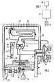
- FIG. 1 shows a block diagram of a Embodiment
- Figure 2 is a device diagram for a gas-fired water heater as another Embodiment.
- a switching means 12 emits a signal to a control unit 10. Depending on this signal, a valve 16 of the control device 10 electrically controlled.
- a gas supply device 14 for a burner 24 can either through a valve 16 or a control valve 34 to be interrupted.
- the valve 16 can be different pressure ratios in two from each other a membrane 18 separate chambers via a second valve 20 and influence a third valve 22.
- the third valve 22 is in a second gas supply device 26 to one Pilot burner 28 housed.
- a water circuit 30 flowing water is through a heat exchanger 32 through the Burner 24 heated.
- the water circuit 30 becomes cold water 46 supplied and after warming it up as hot water 48 taken. With the help of an operating element 42, the Set the desired heat requirement.
- the control unit 10 is powered by a power supply 36, whereby it can be influenced by the switching means 12.
- In one Bracket 38 are both control unit 10, energy supply 36 and the switching means 12 integrated.
- the state a second switching means 44, which opens a Detector valve is detected, the control unit 10 is supplied.
- the second and third valve 20, 22 are over the Control unit 10 controlled.
- the basic arrangement according to FIG. 1 realizes a Safety function of the gas-heated water heater.
- the state of the switching means 12 indicates whether the valve 16 in the sense of its safety position by the control unit 10 is to be controlled. Find as switching means 12 in particular electrical on / off switches, buttons or electrically controlled semiconductor switch use.
- the Control unit 10 assigns the associated output signal of the Switching means 12 to the function desired by the user. in the In the present case, the valve 16 is intended as a Switching means 12 used electrical switches Shut off gas supply to burner 24 completely if that Switching means 12 is open.
- the control unit 10 evaluates this Output signal of the switching means 12, recognizes that the switch used as switching means 12 is open, and assigns the safety position of the valve 16 to this state to.
- the output signal generated by the control unit 10 for the Valve 16 causes its safety position, so that the Gas supply to the burner 24 is prevented. Should he Control unit 10 is permitted above normal operation to communicate the state of the switching means 12, the Cancel safety position of valve 16.
- the user includes the one used as switching means 12 Counter.
- the control unit 10 recognizes in the signal change of the switching means 12 the desire of the user from To switch the safety status to normal operation. The Ignition of the burner 24 can be initiated.
- a valve 16 is suitable, for example, an electrically controllable Magnetic valve. If its energy supply is interrupted, it must Valve 16 will still be able to Safety function. Prevents the Closed position of the valve 16, the gas supply, this must also be guaranteed in the de-energized state. In this case the safety function could also be implemented in this way be that the switching means 12 the energy supply to the valve 16 interrupts. In the open state of the switching means 12 the valve 16 is de-energized, which then Close position ensuring safety function occupies.
- this is Valve 16 designed as a diaphragm valve.
- Different Pressure ratios in the two through the membrane 18 separate chambers influence the position of the Valve 16.
- a change in pressure conditions can be caused by the second and / or third valve 20, 22 is brought about will.
- the second valve 20 controls via a bypass line the gas exchange between the two chambers.
- About the third Valve 22 takes place by means of the second gas supply device 26 the supply to the pilot burner 28.
- Second and third Valves 20, 22 are controlled by control unit 10. in the de-energized state, the second valve 20 is open, the third valve 22 closed.
- the so achieved Pressure conditions in the two chambers cause that Valve 16 is closed and the gas supply to the burner 24 prevents.
- the described state of the valve 16 represents the safety function.
- This safety function is activated if that as Switch designed switching means 12 in the open Condition. Then the power supply 36 of the Control device 10 prevented and the second and third valve 20, 22 are in the de-energized state. When open Switching means 12 cannot heat the water come because the gas supply device 14 through the valve 16th is interrupted.
- the switching means must 12 can be closed by the user.
- Power supply 36 may be batteries, preferably rechargeable, find use. Also a supply over the power grid is conceivable.
- closed Switching means 12 is basically the water heater ready for operation, but the burner 24 has not yet ignited.
- the user sets the with the help of the control element 42 desired water temperature.
- Whose output signal is the control unit 10, which in the signal change Trigger to initiate ignition of burner 24 recognizes.
- the previously closed third valve 22 is open. Pilot gas flows to pilot burner 28 and is there electrically ignited. A monitoring electrode reports the ignition to control unit 10 took place
- the second valve 20 in the open state is then closed.
- the gas in the pilot gas valve chamber burns out and the pressure in this chamber drops.
- the one over the membrane 18 resulting differential pressure opens the valve 16.
- the Gas path via the control valve 34 to the burner 24 Approved.
- the ignited burner 24 heats up Heat exchanger 32 the water circulating in the water circuit 30.
- a constant outlet temperature of the water during the tapping process is achieved via the second membrane 40. It controls the control valve 34 via its stroke is automatically adjusted to the amount of water.
- the end of the dispensing process is closed by closing the Dispensing valve communicated.
- the voltage signal of the second Switching means 44 to the control unit 10 becomes again interrupted.
- the second and third valves 20, 22 return the currentless state of their starting position.
- the third Valve 22 is closed and the second valve 20 open. This causes the differential pressure across the membrane 18 dismantled and the valve 16 closed.
- the flame on Burner 24 goes out.
- As long as the switching means 12 is closed the device remains ready for further taps. With the switching means 12 open, however, a new one Actuation of the nozzle does not trigger an ignition process.
- switching means 12 instead of to interrupt the power supply 36 in one the connecting lines between control unit 10 and the second Switching means 44 to lay. Because when the second is not activated Switching means 44 second and third valve 20, 22 in de-energized state of a valve closure 16 causes this function can also be so Arranged open switching means 12 reach.
- the embodiment shown in Figure 2 ensures a simple test option for the closing function of valve 16, by the switching means 12 when the control valve 34 is open is opened. A proper valve 16 must be then close, after which the burner 24 because of interrupted gas supply device 14 goes out. A two-stage gas release through the valve 16 takes place itself then when the switching means 12 with the control valve 34 open is brought from on to on. A soft, low-noise Ignition is ensured.
- the holding plate 38 forms a receptacle for the control device 10, the switching means 12 and the power supply 36. Im Integrated water heater housing. It can also serve to seal the burner housing. Out For design reasons, the switching means 12 is covered to provide. You must before actuating the switching means 12 to Side to be moved. As another alternative shows for example a lamp the state of the switching means 12 on. The user recognizes the on this display Operating status of the device.
- the holding plate 38 takes also the display. The gas-fired described Water heaters take place especially for that Domestic hot water use.
Landscapes
- Engineering & Computer Science (AREA)
- Physics & Mathematics (AREA)
- Thermal Sciences (AREA)
- Chemical & Material Sciences (AREA)
- Combustion & Propulsion (AREA)
- Mechanical Engineering (AREA)
- General Engineering & Computer Science (AREA)
- Fluid Mechanics (AREA)
- Feeding And Controlling Fuel (AREA)
- Instantaneous Water Boilers, Portable Hot-Water Supply Apparatuses, And Control Of Portable Hot-Water Supply Apparatuses (AREA)
- Regulation And Control Of Combustion (AREA)
Applications Claiming Priority (2)
| Application Number | Priority Date | Filing Date | Title |
|---|---|---|---|
| DE19702686 | 1997-01-25 | ||
| DE19702686A DE19702686A1 (de) | 1997-01-25 | 1997-01-25 | Gasbeheizter Warmwasserbereiter |
Publications (3)
| Publication Number | Publication Date |
|---|---|
| EP0855561A2 true EP0855561A2 (fr) | 1998-07-29 |
| EP0855561A3 EP0855561A3 (fr) | 1999-11-24 |
| EP0855561B1 EP0855561B1 (fr) | 2003-04-16 |
Family
ID=7818361
Family Applications (1)
| Application Number | Title | Priority Date | Filing Date |
|---|---|---|---|
| EP98101037A Expired - Lifetime EP0855561B1 (fr) | 1997-01-25 | 1998-01-22 | Chauffe-eau à gaz |
Country Status (4)
| Country | Link |
|---|---|
| EP (1) | EP0855561B1 (fr) |
| DE (2) | DE19702686A1 (fr) |
| ES (1) | ES2197389T3 (fr) |
| PT (1) | PT855561E (fr) |
Cited By (2)
| Publication number | Priority date | Publication date | Assignee | Title |
|---|---|---|---|---|
| WO1999066270A1 (fr) * | 1998-06-15 | 1999-12-23 | Aos Pty. Ltd. | Vanne de commande de temperature et/ou de pression commandee par un ensemble solenoide temoin de chauffe-eau |
| CN103245062A (zh) * | 2013-05-02 | 2013-08-14 | 佛山市圣柏斯电器有限公司 | 一种电热水器发热体保护结构 |
Families Citing this family (1)
| Publication number | Priority date | Publication date | Assignee | Title |
|---|---|---|---|---|
| EP4108988A1 (fr) * | 2021-06-24 | 2022-12-28 | BDR Thermea Group B.V. | Procédé et dispositif pour commander le fonctionnement d'une chaudière |
Family Cites Families (3)
| Publication number | Priority date | Publication date | Assignee | Title |
|---|---|---|---|---|
| DE2332267C3 (de) * | 1973-06-25 | 1981-07-02 | Gosudarstvennyj naučno-issledovatel'skij i proektnyj institut po ispol'zovaniju gaza v narodnom chozjajstve, proektirovaniju sistem gazonabženija i konstruirovaniju gazovoj apparatury GIPRONIIGAZ, Saratov | Mit Wechselspannung betriebene Steuereinrichtung für Infrarot-Gasbrenner |
| AT388795B (de) * | 1988-02-08 | 1989-08-25 | Vaillant Gmbh | Thermisch beeinflussbarer unterbrecher |
| AT393896B (de) * | 1989-02-13 | 1991-12-27 | Vaillant Gmbh | Brennstoffbeheiztes geraet, z.b. wasserheizer |
-
1997
- 1997-01-25 DE DE19702686A patent/DE19702686A1/de not_active Ceased
-
1998
- 1998-01-22 EP EP98101037A patent/EP0855561B1/fr not_active Expired - Lifetime
- 1998-01-22 PT PT98101037T patent/PT855561E/pt unknown
- 1998-01-22 ES ES98101037T patent/ES2197389T3/es not_active Expired - Lifetime
- 1998-01-22 DE DE59807908T patent/DE59807908D1/de not_active Expired - Lifetime
Cited By (2)
| Publication number | Priority date | Publication date | Assignee | Title |
|---|---|---|---|---|
| WO1999066270A1 (fr) * | 1998-06-15 | 1999-12-23 | Aos Pty. Ltd. | Vanne de commande de temperature et/ou de pression commandee par un ensemble solenoide temoin de chauffe-eau |
| CN103245062A (zh) * | 2013-05-02 | 2013-08-14 | 佛山市圣柏斯电器有限公司 | 一种电热水器发热体保护结构 |
Also Published As
| Publication number | Publication date |
|---|---|
| ES2197389T3 (es) | 2004-01-01 |
| DE59807908D1 (de) | 2003-05-22 |
| DE19702686A1 (de) | 1998-07-30 |
| EP0855561B1 (fr) | 2003-04-16 |
| PT855561E (pt) | 2003-08-29 |
| EP0855561A3 (fr) | 1999-11-24 |
Similar Documents
| Publication | Publication Date | Title |
|---|---|---|
| EP2019614B1 (fr) | Dispositif de chauffage pour une machine a préparer les boissons | |
| EP0855561B1 (fr) | Chauffe-eau à gaz | |
| DE1679447C3 (de) | Steuervorrichtung für die Gas zufuhr von Durchlauferhitzern in Umlaufheizungsanlagen | |
| DE102012003912B3 (de) | Armatur für einen Durchlauf-Wassererhitzer | |
| EP0791159B1 (fr) | Appareil pour le chauffage d'eau de chauffage et d'eau sanitaire | |
| DE10006600A1 (de) | Gasventil und Feuerungsautomat für Gasbrenner | |
| EP1027559B1 (fr) | Chauffe-eau a gaz, notamment chauffe-eau instantane | |
| DE1429115C (de) | Einrichtung zum Steuern eines Gas brenners | |
| DE673028C (de) | Sicherheitsgasbrenner | |
| DE3601046C2 (fr) | ||
| DE627479C (de) | Regelungs- und Sicherungsvorrichtung fuer gasbeheizte Geraete | |
| WO2000057107A1 (fr) | Robinet de regulation de gaz | |
| DE1074842B (de) | Gasbeheizter Durchlauferhitzer mit Wassermangelsicherung | |
| DE667802C (de) | Regelvorrichtung fuer gasbeheizte Geraete | |
| DE2819906A1 (de) | Thermoelektrische abschaltsteuervorrichtung | |
| EP0194637B1 (fr) | Circuit pour commander une source de chaleur chauffée par combustible et chargeant un réservoir à eau sanitaire | |
| DE707946C (de) | Sicherheits- und Regelvorrichtung fuer gasbeheizte Geraete | |
| DE10209193C1 (de) | Elektrisch steuerbares Gasventil | |
| DE2705493C3 (de) | Mischbatterie | |
| DE1233793B (de) | Einrichtung zum Sichern von Gasbrennern von Gasgeraeten | |
| DE903201C (de) | Sicherungsanlage fuer gasbeheizte Geraete | |
| EP1528320B1 (fr) | Armature à gaz | |
| DE624295C (de) | Einrichtung zur Regelung der Gaszufuhr zu gasbeheizten Geraeten | |
| DE19534909A1 (de) | Gerät zum Erwärmen von Heizungswasser und Bereiten von Brauchwasser | |
| AT125823B (de) | Einrichtung zur Verhinderung unerwünschter Gasausströmungen bei Gasverbrauchern jeder Art. |
Legal Events
| Date | Code | Title | Description |
|---|---|---|---|
| PUAI | Public reference made under article 153(3) epc to a published international application that has entered the european phase |
Free format text: ORIGINAL CODE: 0009012 |
|
| AK | Designated contracting states |
Kind code of ref document: A2 Designated state(s): DE ES FR GB IT NL PT |
|
| AX | Request for extension of the european patent |
Free format text: AL;LT;LV;MK;RO;SI |
|
| PUAL | Search report despatched |
Free format text: ORIGINAL CODE: 0009013 |
|
| AK | Designated contracting states |
Kind code of ref document: A3 Designated state(s): AT BE CH DE DK ES FI FR GB GR IE IT LI LU MC NL PT SE |
|
| AX | Request for extension of the european patent |
Free format text: AL;LT;LV;MK;RO;SI |
|
| 17P | Request for examination filed |
Effective date: 20000524 |
|
| AKX | Designation fees paid |
Free format text: DE ES FR GB IT NL PT |
|
| 17Q | First examination report despatched |
Effective date: 20020305 |
|
| GRAG | Despatch of communication of intention to grant |
Free format text: ORIGINAL CODE: EPIDOS AGRA |
|
| GRAG | Despatch of communication of intention to grant |
Free format text: ORIGINAL CODE: EPIDOS AGRA |
|
| GRAH | Despatch of communication of intention to grant a patent |
Free format text: ORIGINAL CODE: EPIDOS IGRA |
|
| GRAH | Despatch of communication of intention to grant a patent |
Free format text: ORIGINAL CODE: EPIDOS IGRA |
|
| GRAA | (expected) grant |
Free format text: ORIGINAL CODE: 0009210 |
|
| AK | Designated contracting states |
Designated state(s): DE ES FR GB IT NL PT |
|
| REG | Reference to a national code |
Ref country code: GB Ref legal event code: FG4D Free format text: NOT ENGLISH |
|
| REF | Corresponds to: |
Ref document number: 59807908 Country of ref document: DE Date of ref document: 20030522 Kind code of ref document: P |
|
| GBT | Gb: translation of ep patent filed (gb section 77(6)(a)/1977) | ||
| ET | Fr: translation filed | ||
| REG | Reference to a national code |
Ref country code: ES Ref legal event code: FG2A Ref document number: 2197389 Country of ref document: ES Kind code of ref document: T3 |
|
| PLBE | No opposition filed within time limit |
Free format text: ORIGINAL CODE: 0009261 |
|
| STAA | Information on the status of an ep patent application or granted ep patent |
Free format text: STATUS: NO OPPOSITION FILED WITHIN TIME LIMIT |
|
| 26N | No opposition filed |
Effective date: 20040119 |
|
| PG25 | Lapsed in a contracting state [announced via postgrant information from national office to epo] |
Ref country code: NL Free format text: LAPSE BECAUSE OF NON-PAYMENT OF DUE FEES Effective date: 20040801 |
|
| NLV4 | Nl: lapsed or anulled due to non-payment of the annual fee |
Effective date: 20040801 |
|
| REG | Reference to a national code |
Ref country code: DE Ref legal event code: R084 Ref document number: 59807908 Country of ref document: DE Effective date: 20120919 |
|
| REG | Reference to a national code |
Ref country code: FR Ref legal event code: PLFP Year of fee payment: 18 |
|
| PGFP | Annual fee paid to national office [announced via postgrant information from national office to epo] |
Ref country code: ES Payment date: 20150122 Year of fee payment: 18 Ref country code: PT Payment date: 20150108 Year of fee payment: 18 Ref country code: IT Payment date: 20150123 Year of fee payment: 18 Ref country code: DE Payment date: 20150324 Year of fee payment: 18 |
|
| PGFP | Annual fee paid to national office [announced via postgrant information from national office to epo] |
Ref country code: FR Payment date: 20150115 Year of fee payment: 18 Ref country code: GB Payment date: 20150123 Year of fee payment: 18 |
|
| REG | Reference to a national code |
Ref country code: DE Ref legal event code: R119 Ref document number: 59807908 Country of ref document: DE |
|
| GBPC | Gb: european patent ceased through non-payment of renewal fee |
Effective date: 20160122 |
|
| REG | Reference to a national code |
Ref country code: FR Ref legal event code: ST Effective date: 20160930 |
|
| PG25 | Lapsed in a contracting state [announced via postgrant information from national office to epo] |
Ref country code: GB Free format text: LAPSE BECAUSE OF NON-PAYMENT OF DUE FEES Effective date: 20160122 Ref country code: DE Free format text: LAPSE BECAUSE OF NON-PAYMENT OF DUE FEES Effective date: 20160802 |
|
| PG25 | Lapsed in a contracting state [announced via postgrant information from national office to epo] |
Ref country code: FR Free format text: LAPSE BECAUSE OF NON-PAYMENT OF DUE FEES Effective date: 20160201 Ref country code: PT Free format text: LAPSE BECAUSE OF NON-PAYMENT OF DUE FEES Effective date: 20160722 |
|
| PG25 | Lapsed in a contracting state [announced via postgrant information from national office to epo] |
Ref country code: IT Free format text: LAPSE BECAUSE OF NON-PAYMENT OF DUE FEES Effective date: 20160122 |
|
| REG | Reference to a national code |
Ref country code: ES Ref legal event code: FD2A Effective date: 20170224 |
|
| PG25 | Lapsed in a contracting state [announced via postgrant information from national office to epo] |
Ref country code: ES Free format text: LAPSE BECAUSE OF NON-PAYMENT OF DUE FEES Effective date: 20160123 |