EP0855563A1 - Canon pour la fabrication de neige - Google Patents
Canon pour la fabrication de neige Download PDFInfo
- Publication number
- EP0855563A1 EP0855563A1 EP98200150A EP98200150A EP0855563A1 EP 0855563 A1 EP0855563 A1 EP 0855563A1 EP 98200150 A EP98200150 A EP 98200150A EP 98200150 A EP98200150 A EP 98200150A EP 0855563 A1 EP0855563 A1 EP 0855563A1
- Authority
- EP
- European Patent Office
- Prior art keywords
- nozzles
- cannon
- ports
- sized capillary
- plan shape
- Prior art date
- Legal status (The legal status is an assumption and is not a legal conclusion. Google has not performed a legal analysis and makes no representation as to the accuracy of the status listed.)
- Granted
Links
- 238000004519 manufacturing process Methods 0.000 title claims description 12
- 238000000889 atomisation Methods 0.000 claims abstract description 27
- 238000002347 injection Methods 0.000 claims abstract description 24
- 239000007924 injection Substances 0.000 claims abstract description 24
- 239000007788 liquid Substances 0.000 claims abstract description 19
- 238000011144 upstream manufacturing Methods 0.000 claims abstract description 6
- 239000012530 fluid Substances 0.000 claims description 12
- 238000000034 method Methods 0.000 claims description 5
- 239000000443 aerosol Substances 0.000 claims description 4
- 230000003247 decreasing effect Effects 0.000 claims description 2
- XLYOFNOQVPJJNP-UHFFFAOYSA-N water Substances O XLYOFNOQVPJJNP-UHFFFAOYSA-N 0.000 claims description 2
- 239000013078 crystal Substances 0.000 description 1
- 230000001419 dependent effect Effects 0.000 description 1
- 239000000203 mixture Substances 0.000 description 1
Images



Classifications
-
- A—HUMAN NECESSITIES
- A62—LIFE-SAVING; FIRE-FIGHTING
- A62C—FIRE-FIGHTING
- A62C5/00—Making of fire-extinguishing materials immediately before use
- A62C5/004—Making of fire-extinguishing materials immediately before use for producing carbon-dioxide snow, carbon-dioxide ice, carbon-dioxide gas, carbon-dioxide liquid, or mixtures thereof
-
- B—PERFORMING OPERATIONS; TRANSPORTING
- B05—SPRAYING OR ATOMISING IN GENERAL; APPLYING FLUENT MATERIALS TO SURFACES, IN GENERAL
- B05B—SPRAYING APPARATUS; ATOMISING APPARATUS; NOZZLES
- B05B1/00—Nozzles, spray heads or other outlets, with or without auxiliary devices such as valves, heating means
- B05B1/02—Nozzles, spray heads or other outlets, with or without auxiliary devices such as valves, heating means designed to produce a jet, spray, or other discharge of particular shape or nature, e.g. in single drops, or having an outlet of particular shape
-
- B—PERFORMING OPERATIONS; TRANSPORTING
- B05—SPRAYING OR ATOMISING IN GENERAL; APPLYING FLUENT MATERIALS TO SURFACES, IN GENERAL
- B05B—SPRAYING APPARATUS; ATOMISING APPARATUS; NOZZLES
- B05B7/00—Spraying apparatus for discharge of liquids or other fluent materials from two or more sources, e.g. of liquid and air, of powder and gas
- B05B7/02—Spray pistols; Apparatus for discharge
- B05B7/04—Spray pistols; Apparatus for discharge with arrangements for mixing liquids or other fluent materials before discharge
- B05B7/0416—Spray pistols; Apparatus for discharge with arrangements for mixing liquids or other fluent materials before discharge with arrangements for mixing one gas and one liquid
- B05B7/0483—Spray pistols; Apparatus for discharge with arrangements for mixing liquids or other fluent materials before discharge with arrangements for mixing one gas and one liquid with gas and liquid jets intersecting in the mixing chamber
-
- B—PERFORMING OPERATIONS; TRANSPORTING
- B05—SPRAYING OR ATOMISING IN GENERAL; APPLYING FLUENT MATERIALS TO SURFACES, IN GENERAL
- B05B—SPRAYING APPARATUS; ATOMISING APPARATUS; NOZZLES
- B05B7/00—Spraying apparatus for discharge of liquids or other fluent materials from two or more sources, e.g. of liquid and air, of powder and gas
- B05B7/02—Spray pistols; Apparatus for discharge
- B05B7/08—Spray pistols; Apparatus for discharge with separate outlet orifices, e.g. to form parallel jets, i.e. the axis of the jets being parallel, to form intersecting jets, i.e. the axis of the jets converging but not necessarily intersecting at a point
- B05B7/0892—Spray pistols; Apparatus for discharge with separate outlet orifices, e.g. to form parallel jets, i.e. the axis of the jets being parallel, to form intersecting jets, i.e. the axis of the jets converging but not necessarily intersecting at a point the outlet orifices for jets constituted by a liquid or a mixture containing a liquid being disposed on a circle
-
- F—MECHANICAL ENGINEERING; LIGHTING; HEATING; WEAPONS; BLASTING
- F25—REFRIGERATION OR COOLING; COMBINED HEATING AND REFRIGERATION SYSTEMS; HEAT PUMP SYSTEMS; MANUFACTURE OR STORAGE OF ICE; LIQUEFACTION SOLIDIFICATION OF GASES
- F25C—PRODUCING, WORKING OR HANDLING ICE
- F25C3/00—Processes or apparatus specially adapted for producing ice or snow for winter sports or similar recreational purposes, e.g. for sporting installations; Producing artificial snow
- F25C3/04—Processes or apparatus specially adapted for producing ice or snow for winter sports or similar recreational purposes, e.g. for sporting installations; Producing artificial snow for sledging or ski trails; Producing artificial snow
-
- F—MECHANICAL ENGINEERING; LIGHTING; HEATING; WEAPONS; BLASTING
- F25—REFRIGERATION OR COOLING; COMBINED HEATING AND REFRIGERATION SYSTEMS; HEAT PUMP SYSTEMS; MANUFACTURE OR STORAGE OF ICE; LIQUEFACTION SOLIDIFICATION OF GASES
- F25C—PRODUCING, WORKING OR HANDLING ICE
- F25C2303/00—Special arrangements or features for producing ice or snow for winter sports or similar recreational purposes, e.g. for sporting installations; Special arrangements or features for producing artificial snow
- F25C2303/048—Snow making by using means for spraying water
- F25C2303/0481—Snow making by using means for spraying water with the use of compressed air
Definitions
- This invention relates to a snow production cannon.
- EP-A-0 250 425, EP-A-0 084 186 and EP-A-0 084 187 describe snow production cannons in accordance with the introduction to claim 1.
- technical progress is continually aimed at increasing the efficiency of said devices, ie increasing the snow quantity produced for equal energy used.
- the main object of the present invention is therefore to provide a snow production cannon of optimum efficiency.
- the main object of the invention is to indicate a method for snow production which increases the efficiency of the atomization stage.
- air is injected by at least one injection nozzle into the pre-mixing chamber (or into the pre-hole of the further nozzle), from which it can leave only through the respective further nozzle (this being the atomization nozzle) to atomize the liquid therein in an optimum manner.
- a further object of the invention is to obtain artificial snow of good quality.
- a further object of the invention is to provide a cannon of simple and economical structure, ie a structure composed of a relatively small number of elements which are joined together in a manner which enables them to be easily assembled and disassembled.
- Figure 1 is a longitudinal section through a snow production cannon according to the invention.
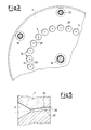
- Figure 2 is a cross-section on the line II-II of Figure 1.
- Figure 3 is a cross-section on the line III-III of Figure 1.
- Figure 4 is a longitudinal section through an injection nozzle.
- Figure 5 is a longitudinal section through an atomization nozzle.
- Figures 6-17 are cross-sections showing the exit ports of injection and/or atomization nozzles constructed in accordance with further embodiments.
- the longitudinal direction is that parallel to the direction of fluid flow through the cannon during operation
- the transverse direction is that perpendicular to the direction of fluid flow through the cannon during operation.
- the cannon of the particular embodiment used to describe the invention is of the type comprising a plurality of nozzles positioned along concentric circles.
- the cannon 1 comprises essentially the following elements, listed in the order of fluid flow through the elements: a first element 2 distributing gas to injection nozzles 3, a second element 4 distributing liquid to a pre-mixing chamber 5, a third element 6 for injecting gas and a fourth element 7 in which the fluid and gas are mixed to form aerosol, with propelling of said aerosol out of the cannon 1.
- the first element 2 can also be connected to the pressurized liquid feed pipe 10.
- the second element 4 is of cone shape, the vertex of which is positioned on the axis 11 of the pressurized liquid feed pipe 10, its base perimeter being tangential to the mouth of the pre-mixing chambers 5.
- the axis 11 coincides with the axis of the cannon 1.
- the third element 6 houses the injection nozzles 3 and comprises a conical hole (not clearly visible) loosely housing the second element 4 such that between the outer surface 12 of the second element 4 and the inner surface 13 of the conical hole there is a passageway 14 for liquid feed to the pre-mixing chambers 5.
- the fourth element 7 comprises the pre-mixing chambers 5 and a plurality of atomization nozzles 15, for which each pre-mixing chamber represents the pre-hole.
- the pipes 9 and 10 are connected to the first element 2 by respective threads 16 and 17.
- the first element 2, the second 4, the third 6 and the fourth 7 are joined together by screws 18 all of which can be manoeuvred from the front of the cannon so as to facilitate assembly and disassembly.
- Annular gaskets 19-21 provide the necessary hydraulic seal between the elements mechanically connected together.
- each injection nozzle 3 comprises, aligned along the axis of symmetry 22 and listed in the order in which the gas flows through them, a pre-hole 23 and a sized capillary hole 24.
- the pre-hole 23 comprises three portions 25-27.
- the first portion 25 is in the form of a cone frustrum converging into the second portion 26.
- the second portion 26 is cylindrical and has a diameter equal to the minor base of the first portion 25.
- the third portion 27 is in the form of a cone frustrum converging into the sized capillary hole 24 in which the minor base has a diameter greater than the dimensions of said sized capillary hole 24.
- Each atomization nozzle 15 comprises, aligned along the axis of symmetry 28 and listed in the order in which the fluid flows through them, a pre-hole 5 and a sized capillary hole 29.
- the pre-hole of the atomization nozzle is the pre-mixing chamber 5, in the shape of a cone frustum converging into the sized capillary hole 29.
- the axes of symmetry 28 of each atomization nozzle 15 cut the axis 11 of the cannon 1.
- the angle of incidence a is about 7°.
- the ports of the sized capillary holes 29 and 24 of the atomization nozzles 15 and injection nozzles 3 have ports of equal shape, however said ports could be of different shape, and/or of variously assorted forms.
- the ports of the sized capillary holes 29 and 24 of the atomization nozzles 15 and injection nozzles 3 are of circular shape.
- the ports of the sized capillary holes 24, 29 of the nozzles have the following geometrical plan shape: at least two lobes oppositely positioned about the central projection axis of the nozzle.
- the ports of the sized capillary holes 24, 29 of the nozzles have the following geometrical plan shape: two lobes oppositely positioned about the central projection axis of the nozzle and having right-angled ends.
- the ports of the sized capillary holes of the nozzles have the following geometrical plan shape: two lobes oppositely positioned about the central projection axis of the nozzle and having rounded ends.
- the ports of the sized capillary holes 24, 29 of the nozzles have the following geometrical plan shape: three lobes positioned 120° apart about the central projection axis of the nozzle and having right-angled ends.
- the ports of the sized capillary holes 24, 29 of the nozzles have the following geometrical plan shape: three lobes positioned 120° apart about the central projection axis of the nozzle and having rounded ends.
- the ports of the sized capillary holes 24, 29 of the nozzles have the following geometrical plan shape: three lobes positioned 120° apart about the central projection axis of the nozzle and having rounded ends, with the width of the lobes decreasing from the central axis towards the outside.
- the ports of the sized capillary holes 24, 29 of the nozzles have the following geometrical plan shape: three lobes positioned 120° apart about the central projection axis of the nozzle and having right-angled ends in which two lobes have equal length, which is less than the remaining lobe.
- the ports of the sized capillary holes 24, 29 of the nozzles have the following geometrical plan shape: four lobes oppositely positioned about the central projection axis of the nozzle, ie cross-shaped and having right-angled ends.
- the ports of the sized capillary holes 24, 29 of the nozzles have the following geometrical plan shape: four lobes oppositely positioned about the central projection axis of the nozzle, and having rounded ends.
- the ports of the sized capillary holes 24, 29 of the nozzles have the following geometrical plan shape: five lobes oppositely positioned about tne central projection axis of the nozzle, and having right-angled ends.
- the ports of the sized capillary holes 24, 29 of the nozzles have the following geometrical plan shape: five lobes oppositely positioned about the central projection axis of the nozzle, and having rounded ends.
- the ports of the sized capillary holes 24, 29 of the nozzles have the following geometrical plan shape: six lobes oppositely positioned about the central projection axis of the nozzle, and having right-angled ends.
- the ports of the sized capillary holes 24, 29 of the nozzles have the following geometrical plan shape: six lobes oppositely positioned about the central projection axis of the nozzle, and having rounded ends.
- the ports of the sized capillary holes 24, 29 of the nozzles have the following geometrical plan shape: eight lobes oppositely positioned about the central projection axis of the nozzle, and having right-angled ends.
- the ports of the sized capillary holes 24, 29 of the nozzles have the following geometrical plan shape: eight lobes oppositely positioned about the central projection axis of the nozzle, and having rounded ends.
- the ports of the sized capillary holes 24, 29 of the nozzles have the following geometrical plan shape: triangular.
- the ports of the sized capillary holes 24, 29 of the nozzles have the following geometrical plan shape: triangular with rounded vertices.
- the ports of the sized capillary holes 24, 29 of the nozzles have the following geometrical plan shape: at least two lobes oppositely positioned about the central projection axis of the nozzle, and along which pairs of circular holes are provided in symmetrical positions.
- capillaries with the aforestated geometrical forms enables artificial snow crystals of different shapes to be formed.
- the cannon 1 essentially implements a method for artificial snow production comprising a first stage of gas injection into the liquid while this is upstream of the atomization nozzle 15.
- the injection stage is accomplished by passing the liquid through the injection nozzle 3 which opens into a pre-injection chamber 5 positioned upstream of the atomization nozzle 15.
- the gas is air and the liquid is water.
Landscapes
- Engineering & Computer Science (AREA)
- Physics & Mathematics (AREA)
- Mechanical Engineering (AREA)
- Public Health (AREA)
- Business, Economics & Management (AREA)
- Emergency Management (AREA)
- Chemical & Material Sciences (AREA)
- Chemical Kinetics & Catalysis (AREA)
- Health & Medical Sciences (AREA)
- Thermal Sciences (AREA)
- General Engineering & Computer Science (AREA)
- Pharmaceuticals Containing Other Organic And Inorganic Compounds (AREA)
- Nozzles (AREA)
- Materials Applied To Surfaces To Minimize Adherence Of Mist Or Water (AREA)
- Medicines Containing Plant Substances (AREA)
Applications Claiming Priority (2)
| Application Number | Priority Date | Filing Date | Title |
|---|---|---|---|
| IT97MI000124A IT1289191B1 (it) | 1997-01-23 | 1997-01-23 | Cannone per la produzione di neve |
| ITMI970124 | 1997-01-23 |
Publications (2)
| Publication Number | Publication Date |
|---|---|
| EP0855563A1 true EP0855563A1 (fr) | 1998-07-29 |
| EP0855563B1 EP0855563B1 (fr) | 2003-01-02 |
Family
ID=11375714
Family Applications (1)
| Application Number | Title | Priority Date | Filing Date |
|---|---|---|---|
| EP98200150A Expired - Lifetime EP0855563B1 (fr) | 1997-01-23 | 1998-01-21 | Canon pour la fabrication de neige |
Country Status (4)
| Country | Link |
|---|---|
| EP (1) | EP0855563B1 (fr) |
| AT (1) | ATE230475T1 (fr) |
| DE (1) | DE69810358D1 (fr) |
| IT (1) | IT1289191B1 (fr) |
Cited By (4)
| Publication number | Priority date | Publication date | Assignee | Title |
|---|---|---|---|---|
| DE102008017620A1 (de) * | 2008-04-04 | 2009-11-19 | Snowbox Schnee- Und Eistechnik Gmbh | Vorrichtung zur Erzeugung von Schnee, insbesondere Schneedüse, bzw. Schnee-Erzeugungs-Vorrichtung zur Erzeugung von Schnee |
| US20110127347A1 (en) * | 2008-06-04 | 2011-06-02 | Jude Alexander Glynn Worthy | improved mist generating apparatus and method |
| NL2007431C2 (nl) * | 2011-03-28 | 2012-10-01 | Marel Townsend Further Proc Bv | Sproeikop, sproei-inrichting, productielijn en werkwijze voor het ten minste gedeeltelijk met een vloeibaar consumabel medium bedekken van voedseldelen. |
| CN106362886A (zh) * | 2016-10-26 | 2017-02-01 | 浙江环兴机械有限公司 | 适于将污泥直接喷雾至干化塔的雾化器及其操作方法 |
Citations (15)
| Publication number | Priority date | Publication date | Assignee | Title |
|---|---|---|---|---|
| DE69932C (de) * | E. G. VON MONTMORE in Wien V., Wienstr. 79 | Zerstäubungsdüse für Luftbefeuchtungs- und Lufterneuerungsvorrichtungen | ||
| GB628083A (en) * | 1947-08-25 | 1949-08-22 | Edward George Cribb | Improvements relating to devices for atomising liquids |
| US2676471A (en) * | 1950-12-14 | 1954-04-27 | Tey Mfg Corp | Method for making and distributing snow |
| US2678236A (en) * | 1952-04-05 | 1954-05-11 | Kewanee Ross Corp | Spray nozzle |
| US2960064A (en) * | 1957-04-18 | 1960-11-15 | Davy & United Eng Co Ltd | Nozzles |
| US3421693A (en) * | 1963-09-27 | 1969-01-14 | Sames Mach Electrostat | Pneumatic atomizer for spraying liquids |
| US3908903A (en) * | 1974-02-11 | 1975-09-30 | Jr Samuel L Burns | Snow making apparatus and method |
| US3945567A (en) * | 1975-07-17 | 1976-03-23 | Gerry Rambach | Snow making apparatus |
| EP0084187A1 (fr) | 1982-01-18 | 1983-07-27 | Michael Manhart | Canon à neige |
| EP0084186A1 (fr) | 1982-01-18 | 1983-07-27 | Michael Manhart | Canon à neige |
| EP0101109A2 (fr) * | 1982-08-09 | 1984-02-22 | Shell Internationale Researchmaatschappij B.V. | Atomiseur-mélangeur |
| US4655395A (en) * | 1984-04-17 | 1987-04-07 | The Babcock & Wilcox Company | Adjustable conical atomizer |
| EP0250425A1 (fr) | 1985-03-27 | 1988-01-07 | Pierre Chanel | Dispositif et procede de fabrication de neige artificielle. |
| US4730774A (en) * | 1987-01-12 | 1988-03-15 | Shippee James H | Dual pressure compensating snowmaking apparatus |
| US5083707A (en) * | 1990-03-05 | 1992-01-28 | Dendrite Associates, Inc. | Nucleator |
-
1997
- 1997-01-23 IT IT97MI000124A patent/IT1289191B1/it active IP Right Grant
-
1998
- 1998-01-21 AT AT98200150T patent/ATE230475T1/de not_active IP Right Cessation
- 1998-01-21 EP EP98200150A patent/EP0855563B1/fr not_active Expired - Lifetime
- 1998-01-21 DE DE69810358T patent/DE69810358D1/de not_active Expired - Lifetime
Patent Citations (15)
| Publication number | Priority date | Publication date | Assignee | Title |
|---|---|---|---|---|
| DE69932C (de) * | E. G. VON MONTMORE in Wien V., Wienstr. 79 | Zerstäubungsdüse für Luftbefeuchtungs- und Lufterneuerungsvorrichtungen | ||
| GB628083A (en) * | 1947-08-25 | 1949-08-22 | Edward George Cribb | Improvements relating to devices for atomising liquids |
| US2676471A (en) * | 1950-12-14 | 1954-04-27 | Tey Mfg Corp | Method for making and distributing snow |
| US2678236A (en) * | 1952-04-05 | 1954-05-11 | Kewanee Ross Corp | Spray nozzle |
| US2960064A (en) * | 1957-04-18 | 1960-11-15 | Davy & United Eng Co Ltd | Nozzles |
| US3421693A (en) * | 1963-09-27 | 1969-01-14 | Sames Mach Electrostat | Pneumatic atomizer for spraying liquids |
| US3908903A (en) * | 1974-02-11 | 1975-09-30 | Jr Samuel L Burns | Snow making apparatus and method |
| US3945567A (en) * | 1975-07-17 | 1976-03-23 | Gerry Rambach | Snow making apparatus |
| EP0084187A1 (fr) | 1982-01-18 | 1983-07-27 | Michael Manhart | Canon à neige |
| EP0084186A1 (fr) | 1982-01-18 | 1983-07-27 | Michael Manhart | Canon à neige |
| EP0101109A2 (fr) * | 1982-08-09 | 1984-02-22 | Shell Internationale Researchmaatschappij B.V. | Atomiseur-mélangeur |
| US4655395A (en) * | 1984-04-17 | 1987-04-07 | The Babcock & Wilcox Company | Adjustable conical atomizer |
| EP0250425A1 (fr) | 1985-03-27 | 1988-01-07 | Pierre Chanel | Dispositif et procede de fabrication de neige artificielle. |
| US4730774A (en) * | 1987-01-12 | 1988-03-15 | Shippee James H | Dual pressure compensating snowmaking apparatus |
| US5083707A (en) * | 1990-03-05 | 1992-01-28 | Dendrite Associates, Inc. | Nucleator |
Cited By (8)
| Publication number | Priority date | Publication date | Assignee | Title |
|---|---|---|---|---|
| DE102008017620A1 (de) * | 2008-04-04 | 2009-11-19 | Snowbox Schnee- Und Eistechnik Gmbh | Vorrichtung zur Erzeugung von Schnee, insbesondere Schneedüse, bzw. Schnee-Erzeugungs-Vorrichtung zur Erzeugung von Schnee |
| DE102008017620B4 (de) * | 2008-04-04 | 2010-04-08 | Snowbox Schnee- Und Eistechnik Gmbh | Vorrichtung zur Erzeugung von Schnee, insbesondere Schneedüse, bzw. Schnee-Erzeugungs-Vorrichtung |
| US20110127347A1 (en) * | 2008-06-04 | 2011-06-02 | Jude Alexander Glynn Worthy | improved mist generating apparatus and method |
| US8991727B2 (en) * | 2008-06-04 | 2015-03-31 | Tyco Fire & Security Gmbh | Mist generating apparatus and method |
| NL2007431C2 (nl) * | 2011-03-28 | 2012-10-01 | Marel Townsend Further Proc Bv | Sproeikop, sproei-inrichting, productielijn en werkwijze voor het ten minste gedeeltelijk met een vloeibaar consumabel medium bedekken van voedseldelen. |
| WO2012134282A3 (fr) * | 2011-03-28 | 2012-12-27 | Marel Meat Processing B.V. | Buse de pulvérisation, dispositif de pulvérisation, chaîne de production et procédé pour revêtir au moins partiellement des parties d'aliment par un milieu consommable liquide |
| CN106362886A (zh) * | 2016-10-26 | 2017-02-01 | 浙江环兴机械有限公司 | 适于将污泥直接喷雾至干化塔的雾化器及其操作方法 |
| CN106362886B (zh) * | 2016-10-26 | 2019-03-26 | 浙江环兴机械有限公司 | 适于将污泥直接喷雾至干化塔的雾化器的操作方法 |
Also Published As
| Publication number | Publication date |
|---|---|
| EP0855563B1 (fr) | 2003-01-02 |
| ATE230475T1 (de) | 2003-01-15 |
| DE69810358D1 (de) | 2003-02-06 |
| ITMI970124A1 (it) | 1998-07-23 |
| IT1289191B1 (it) | 1998-09-29 |
Similar Documents
| Publication | Publication Date | Title |
|---|---|---|
| KR100231240B1 (ko) | 개량된 플랫 팬 스프레이 노즐 | |
| US6047903A (en) | Fluid flow conditioner | |
| US3601320A (en) | Apparatus for breaking up a directional fluid stream | |
| US4087050A (en) | Swirl type pressure fuel atomizer | |
| US4708293A (en) | Atomizer for viscous liquid fuels | |
| CN101495239B (zh) | 用于连续金属铸造冷却的全锥式空气辅助喷嘴 | |
| US5280705A (en) | Fuel injection system for scramjet engines | |
| KR20010074499A (ko) | 차동 인젝터 | |
| EP0746420A4 (fr) | Buse de pulverisation a assistance pneumatique | |
| US2605144A (en) | Nozzle | |
| US4246936A (en) | Pipe for trickle irrigation | |
| EP0855563B1 (fr) | Canon pour la fabrication de neige | |
| FI110696B (fi) | Parannuksia siistattavaan paperimassavirtaan ilmaa injektoiviin laitteisiin | |
| SU503600A1 (ru) | Струйно-центробежна форсунка | |
| US4127234A (en) | Multi orifice structure and method of making same | |
| FI71005C (fi) | Snoekanon | |
| EP4140595A1 (fr) | Buse d'injection de brouillard améliorée | |
| SU1533767A1 (ru) | Многодисковый распылитель жидкости | |
| EP0855564A1 (fr) | Canon pour la fabrication de neige | |
| RU2612483C1 (ru) | Пневматическая форсунка кочетова | |
| EP0092002A1 (fr) | Pulvérisateur de combustible pour des brûleurs à mazout | |
| US7584908B2 (en) | Spray nozzle apparatus and method | |
| CN113266398B (zh) | 一种降低潮法喷射混凝土回弹率的喷枪及方法 | |
| SU1216454A1 (ru) | Газовый эжектор | |
| RU2324078C2 (ru) | Жидкостно-газовый эжектор |
Legal Events
| Date | Code | Title | Description |
|---|---|---|---|
| PUAI | Public reference made under article 153(3) epc to a published international application that has entered the european phase |
Free format text: ORIGINAL CODE: 0009012 |
|
| AK | Designated contracting states |
Kind code of ref document: A1 Designated state(s): AT CH DE ES FI FR IT LI SE |
|
| AX | Request for extension of the european patent |
Free format text: AL;LT;LV;MK;RO;SI |
|
| 17P | Request for examination filed |
Effective date: 19981222 |
|
| AKX | Designation fees paid |
Free format text: AT CH DE ES FI FR IT LI SE |
|
| RBV | Designated contracting states (corrected) |
Designated state(s): AT CH DE ES FI FR IT LI SE |
|
| 17Q | First examination report despatched |
Effective date: 20001129 |
|
| GRAG | Despatch of communication of intention to grant |
Free format text: ORIGINAL CODE: EPIDOS AGRA |
|
| GRAG | Despatch of communication of intention to grant |
Free format text: ORIGINAL CODE: EPIDOS AGRA |
|
| GRAH | Despatch of communication of intention to grant a patent |
Free format text: ORIGINAL CODE: EPIDOS IGRA |
|
| GRAH | Despatch of communication of intention to grant a patent |
Free format text: ORIGINAL CODE: EPIDOS IGRA |
|
| GRAA | (expected) grant |
Free format text: ORIGINAL CODE: 0009210 |
|
| AK | Designated contracting states |
Kind code of ref document: B1 Designated state(s): AT CH DE ES FI FR IT LI SE |
|
| PG25 | Lapsed in a contracting state [announced via postgrant information from national office to epo] |
Ref country code: LI Free format text: LAPSE BECAUSE OF FAILURE TO SUBMIT A TRANSLATION OF THE DESCRIPTION OR TO PAY THE FEE WITHIN THE PRESCRIBED TIME-LIMIT Effective date: 20030102 Ref country code: IT Free format text: LAPSE BECAUSE OF FAILURE TO SUBMIT A TRANSLATION OF THE DESCRIPTION OR TO PAY THE FEE WITHIN THE PRESCRIBED TIME-LIMIT;WARNING: LAPSES OF ITALIAN PATENTS WITH EFFECTIVE DATE BEFORE 2007 MAY HAVE OCCURRED AT ANY TIME BEFORE 2007. THE CORRECT EFFECTIVE DATE MAY BE DIFFERENT FROM THE ONE RECORDED. Effective date: 20030102 Ref country code: FR Free format text: LAPSE BECAUSE OF FAILURE TO SUBMIT A TRANSLATION OF THE DESCRIPTION OR TO PAY THE FEE WITHIN THE PRESCRIBED TIME-LIMIT Effective date: 20030102 Ref country code: FI Free format text: LAPSE BECAUSE OF FAILURE TO SUBMIT A TRANSLATION OF THE DESCRIPTION OR TO PAY THE FEE WITHIN THE PRESCRIBED TIME-LIMIT Effective date: 20030102 Ref country code: CH Free format text: LAPSE BECAUSE OF FAILURE TO SUBMIT A TRANSLATION OF THE DESCRIPTION OR TO PAY THE FEE WITHIN THE PRESCRIBED TIME-LIMIT Effective date: 20030102 Ref country code: AT Free format text: LAPSE BECAUSE OF FAILURE TO SUBMIT A TRANSLATION OF THE DESCRIPTION OR TO PAY THE FEE WITHIN THE PRESCRIBED TIME-LIMIT Effective date: 20030102 |
|
| REF | Corresponds to: |
Ref document number: 230475 Country of ref document: AT Date of ref document: 20030115 Kind code of ref document: T |
|
| REG | Reference to a national code |
Ref country code: CH Ref legal event code: EP |
|
| REF | Corresponds to: |
Ref document number: 69810358 Country of ref document: DE Date of ref document: 20030206 Kind code of ref document: P |
|
| PG25 | Lapsed in a contracting state [announced via postgrant information from national office to epo] |
Ref country code: SE Free format text: LAPSE BECAUSE OF FAILURE TO SUBMIT A TRANSLATION OF THE DESCRIPTION OR TO PAY THE FEE WITHIN THE PRESCRIBED TIME-LIMIT Effective date: 20030402 |
|
| PG25 | Lapsed in a contracting state [announced via postgrant information from national office to epo] |
Ref country code: DE Free format text: LAPSE BECAUSE OF FAILURE TO SUBMIT A TRANSLATION OF THE DESCRIPTION OR TO PAY THE FEE WITHIN THE PRESCRIBED TIME-LIMIT Effective date: 20030403 |
|
| REG | Reference to a national code |
Ref country code: CH Ref legal event code: PL |
|
| PG25 | Lapsed in a contracting state [announced via postgrant information from national office to epo] |
Ref country code: ES Free format text: LAPSE BECAUSE OF FAILURE TO SUBMIT A TRANSLATION OF THE DESCRIPTION OR TO PAY THE FEE WITHIN THE PRESCRIBED TIME-LIMIT Effective date: 20030730 |
|
| PLBE | No opposition filed within time limit |
Free format text: ORIGINAL CODE: 0009261 |
|
| STAA | Information on the status of an ep patent application or granted ep patent |
Free format text: STATUS: NO OPPOSITION FILED WITHIN TIME LIMIT |
|
| EN | Fr: translation not filed | ||
| 26N | No opposition filed |
Effective date: 20031003 |