EP0855576A1 - Procédé et dispositif pour la mesure du débit d'un fluide en écoulement - Google Patents
Procédé et dispositif pour la mesure du débit d'un fluide en écoulement Download PDFInfo
- Publication number
- EP0855576A1 EP0855576A1 EP97101162A EP97101162A EP0855576A1 EP 0855576 A1 EP0855576 A1 EP 0855576A1 EP 97101162 A EP97101162 A EP 97101162A EP 97101162 A EP97101162 A EP 97101162A EP 0855576 A1 EP0855576 A1 EP 0855576A1
- Authority
- EP
- European Patent Office
- Prior art keywords
- liquid
- gas
- installation according
- measuring
- detected
- Prior art date
- Legal status (The legal status is an assumption and is not a legal conclusion. Google has not performed a legal analysis and makes no representation as to the accuracy of the status listed.)
- Withdrawn
Links
- 238000000034 method Methods 0.000 title claims abstract description 22
- 239000012530 fluid Substances 0.000 title description 2
- 239000007788 liquid Substances 0.000 claims abstract description 101
- 238000007872 degassing Methods 0.000 claims description 13
- 238000006073 displacement reaction Methods 0.000 claims description 11
- 238000005259 measurement Methods 0.000 claims description 11
- 230000005484 gravity Effects 0.000 claims description 8
- 238000012360 testing method Methods 0.000 claims description 4
- 230000003287 optical effect Effects 0.000 claims description 3
- 230000005540 biological transmission Effects 0.000 claims description 2
- 230000001419 dependent effect Effects 0.000 claims description 2
- 238000009434 installation Methods 0.000 claims 13
- 238000001514 detection method Methods 0.000 claims 1
- 238000010943 off-gassing Methods 0.000 claims 1
- 238000011144 upstream manufacturing Methods 0.000 claims 1
- 239000007789 gas Substances 0.000 description 54
- 238000005516 engineering process Methods 0.000 description 4
- 230000000694 effects Effects 0.000 description 2
- 238000011156 evaluation Methods 0.000 description 2
- 230000005855 radiation Effects 0.000 description 2
- 238000012546 transfer Methods 0.000 description 2
- 238000009825 accumulation Methods 0.000 description 1
- 230000033228 biological regulation Effects 0.000 description 1
- 230000015572 biosynthetic process Effects 0.000 description 1
- 230000001914 calming effect Effects 0.000 description 1
- 238000010276 construction Methods 0.000 description 1
- 238000011109 contamination Methods 0.000 description 1
- 230000008878 coupling Effects 0.000 description 1
- 238000010168 coupling process Methods 0.000 description 1
- 238000005859 coupling reaction Methods 0.000 description 1
- 230000007423 decrease Effects 0.000 description 1
- 239000002283 diesel fuel Substances 0.000 description 1
- 238000010438 heat treatment Methods 0.000 description 1
- 238000012545 processing Methods 0.000 description 1
- 238000005086 pumping Methods 0.000 description 1
- 230000001105 regulatory effect Effects 0.000 description 1
- 238000005204 segregation Methods 0.000 description 1
- 230000035945 sensitivity Effects 0.000 description 1
- 238000009423 ventilation Methods 0.000 description 1
- 238000013022 venting Methods 0.000 description 1
Images
Classifications
-
- B—PERFORMING OPERATIONS; TRANSPORTING
- B67—OPENING, CLOSING OR CLEANING BOTTLES, JARS OR SIMILAR CONTAINERS; LIQUID HANDLING
- B67D—DISPENSING, DELIVERING OR TRANSFERRING LIQUIDS, NOT OTHERWISE PROVIDED FOR
- B67D7/00—Apparatus or devices for transferring liquids from bulk storage containers or reservoirs into vehicles or into portable containers, e.g. for retail sale purposes
- B67D7/06—Details or accessories
- B67D7/78—Arrangements of storage tanks, reservoirs or pipe-lines
-
- B—PERFORMING OPERATIONS; TRANSPORTING
- B67—OPENING, CLOSING OR CLEANING BOTTLES, JARS OR SIMILAR CONTAINERS; LIQUID HANDLING
- B67D—DISPENSING, DELIVERING OR TRANSFERRING LIQUIDS, NOT OTHERWISE PROVIDED FOR
- B67D7/00—Apparatus or devices for transferring liquids from bulk storage containers or reservoirs into vehicles or into portable containers, e.g. for retail sale purposes
- B67D7/06—Details or accessories
- B67D7/08—Arrangements of devices for controlling, indicating, metering or registering quantity or price of liquid transferred
-
- G—PHYSICS
- G01—MEASURING; TESTING
- G01F—MEASURING VOLUME, VOLUME FLOW, MASS FLOW OR LIQUID LEVEL; METERING BY VOLUME
- G01F1/00—Measuring the volume flow or mass flow of fluid or fluent solid material wherein the fluid passes through a meter in a continuous flow
-
- G—PHYSICS
- G01—MEASURING; TESTING
- G01F—MEASURING VOLUME, VOLUME FLOW, MASS FLOW OR LIQUID LEVEL; METERING BY VOLUME
- G01F1/00—Measuring the volume flow or mass flow of fluid or fluent solid material wherein the fluid passes through a meter in a continuous flow
- G01F1/74—Devices for measuring flow of a fluid or flow of a fluent solid material in suspension in another fluid
-
- G—PHYSICS
- G01—MEASURING; TESTING
- G01F—MEASURING VOLUME, VOLUME FLOW, MASS FLOW OR LIQUID LEVEL; METERING BY VOLUME
- G01F15/00—Details of, or accessories for, apparatus of groups G01F1/00 - G01F13/00 insofar as such details or appliances are not adapted to particular types of such apparatus
- G01F15/08—Air or gas separators in combination with liquid meters; Liquid separators in combination with gas-meters
Definitions
- the invention relates to a method and a system for measuring the volume of liquids flowing through avoiding measurement errors due to impermissibly high gas proportions.
- the method and system are particularly suitable for use in Tank vehicles intended, for example for heating oil or for diesel fuel.
- dispensing liquid is a Air entry possible due to operational reasons Change from a chamber of the tanker to be emptied to another chamber or when emptying a chamber entry. Gassing the liquid can are also based on leaks in the pipe system. Further can result in an air entry when gravity is conveyed Negative pressure in the pipe system. Gas fractions however, falsify the measurement of the dispensed volume of liquid. Calibration regulations for volume measurement therefore prescribe that the gas portion of the liquid permissible values must not exceed.
- the object of the invention is a method and a system for measuring the volume flowing fluid with reduced technical Effort, greater performance and reduced To create space.
- the gas content of the liquid flowing through the line is permanent or recorded at intervals. It also becomes dependent on the deviation of the detected gas fraction from a permissible value of the volume flow of the liquid in influenced the sense that he at least with excessive gas content is reduced until the gas content of the Liquid has reached the permissible value. Conversely, can with a gas content below the permissible value of Volume flow are increased until the gas content of the Liquid assumes the permissible value.
- the Invention made use of the knowledge that the gas content the liquid through self-degassing at reduced Flow rate decreases. This proportion of gas is in a Gas bubble sensor downstream container or in a calming section collected and from a certain level the liquid is drained when the liquid stops.
- the Invention uses the dependency on gas content and flow rate but not for simple two-point switching, which as states only the complete flow interruption and knows full volume flow output. Much more it provides the volume flow depending on the determined deviation of the detected gas proportion from the permissible Influence value in several stages and / or continuously. In this way it is achieved that the volume flowing liquid always with a calibrated Levy is determined.
- the person subject to calibration can Liquid flow along a specified calibration error limit to close to the separate liquid / air phase flow be regulated down without the liquid release must be interrupted and the measuring system makes improper mistakes.
- the custody transfer So tankers can be very efficient without frequent annoying switching on and off of the measuring system respectively.
- the measuring system can be much smaller, made lighter and more variable by the vehicle body and be installed.
- the permissible value of the gas portion can be adjustable so that the measuring technology can be adapted to the respective requirements is. It is also advantageous that an electronic Processing the measured variable and determining the manipulated variable is possible, with already existing electronics such measuring systems can be used.
- gas bubble sensor for use come. This can change the gas content optically or acoustically capture, e.g. due to reflection effects. For this a light transmitter and Be assigned to the light receiver. To determine a corrected value, the device can detect the gas content check.
- the gas bubble sensor of this new imprint has one Evaluation electronics capable of being in a momentary Liquid flow existing air share quantitatively to determine.
- the same facility can also do the allowed Monitor the liquid level of the degassing device, by one if the value falls below a permissible value Trigger venting process. As mentioned above, it happens at low throughput speeds segregation of liquid in the pipeline and gas, in which, however, the gas volume from measurement technology Reasons do not exceed certain limits may.
- Test signal light beam or directional acoustic signal
- the reflection of the test signal perpendicular to its direction of transmission can be detected and the gas content of the liquid can be determined from the quotient of the recorded values.
- This quotient formation significantly reduces interference e.g. due to turbidity of the medium or due to contamination of sensors.
- the liquid can pass through a positive displacement pump the line section can be pumped. If the liquid is pumped while overcoming a back pressure that can be generated by a pressure control valve breaks an air inclusion together the volume flow in the pump. As a result, the permissible value of the gas content can already be the liquid can be reached. So the pump can the devices for detecting the gas content, for determining the deviation from the permissible value and to influence the volume flow of the liquid in simple measuring system designs replace. This effect is preferred however used in conjunction with the facilities mentioned.
- the device for influencing the volume flow is preferably a pump with adjustable volume flow. This can be driven at constant speed and to influence the Volume flow from an adjustable pressure relief valve be bridged.
- the line section can also be used to convey the liquid be designed as a gravity line. Then can as a device for influencing the volume flow of the Serve liquid an adjustable valve.
- the measuring technique is preferably combined with degassing.
- a collection container can be considerably smaller than performed in known degassing devices (e.g. about 6 versus 20 to 25 liters).
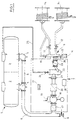
- FIG. 1 is a tank 1 of a tank truck in different Tank chambers 2, 3 divided. These are via connecting pieces 4, 5 and pipes 6 to a measuring system 7 connected in the drawing within the dash-dotted system boundary. In front of the measuring system 7, the liquid can if necessary via a valve 8 subtracted from. There is a behind the measuring system 7 Liquid distributor 9, the liquid through shut-off devices 10, 11, 12, 13 on hose reels 14, 15 or one Plug-in coupling 16 passes on.
- the measuring system 7 has a pump protection filter on the input side 17, through which the liquid to a constant speed operated displacement pump 18 is forwarded.
- the Displacement pump 18 is of a pneumatically controlled type Overflow valve 19 bridges.
- a counter protection filter 20 On the pressure side of the positive displacement pump 18 is a counter protection filter 20 connected. Behind the meter protection filter 20 the liquid becomes a gas bubble sensor 21 performed, the construction of which is described in more detail below becomes. At the output of the gas bubble sensor 21 is a degassing tank 22 connected. From the gas bubble sensor 21 the liquid reaches approximately in the upper region of the Degassing tank 22. Near the bottom of the degassing tank 22 it is withdrawn and a device for measuring of the volume supplied in the form of a counter 23.
- a vent valve 24 connected, via a line 25 with the Chambers 2, 3 of the tank 1 is connected.
- the output of the counter 23 is with a pressure control valve 26 connected. At the output of the pressure control valve 26 is the Measuring device 7 connected to the liquid distributor 9.
- the measuring device 7 also has an electronic one Control 27 and a pneumatic control 28.
- the electronic control 27 is with the gas bubble sensor 21 connected and evaluates its signals. It delivers Control signals for the pneumatic control 28, which controls the various valves of the system. Furthermore can to the controls 27, 28 registration and display devices be connected.
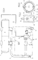
- the gas bubble sensor 21 has a substantially cylindrical base body 29 with connecting flanges 30, 31 at both ends.
- an infrared light transmitter and receiver 32 installed, one diagonally through the cross section of the base body Has 29 directed outer axis.
- a prism 33 is placed, which lets IR radiation through in the presence of liquid and in the absence of liquid inside the transmitter and receiver 32 redirects. The reflected light is from the integrated receiver of the transmitter and receiver 32 detected.
- An IR receiver 34 is arranged at the bottom of the base body, on the outside axis of the transmitter and receiver 32 is aligned.
- Another receiver is 35 in integrated the upper area of the base body 29. This Receiver 35 is perpendicular to the outside axis of the transmitter and receiver 32 aligned.
- a subordinate evaluation device forms the quotients from the radiation values measured by the receivers 34 and 35. This quotient is influenced by interference largely independent.
- the gas bubble sensor 21 is also a level sensor. If namely the liquid level under the prism 33 at the bottom End of the transmitter and receiver 32 falls, detected the built-in receiver incidence of light and shows that Fall below this liquid level. For one The displayed liquid level can be adjusted Transmitter and receiver 32 slidable on the diagonal axis and can be locked in any sliding position.
- the gas bubble sensor 21 detects the respective gas bubble fraction or the level of the liquid. If exceeded
- the controls 27, 28 ensure a permissible value by adjusting the overflow valve 19 for a change of the liquid flow until the permissible value is reached or falls below. Will be the allowable value the liquid flow can drop through appropriate control measures until they are reached of the permissible value can be increased. If the liquid level in the line system among those of transmitter and Receiver 32 falls in the gas bubble sensor detectable value, there is a risk of impermissibly high gas proportions. Then the controls 27, 28 ensure that none more liquid gets into the measuring system 7 and vent the vent container 22 via the vent valve 24th
- a connection piece 16 is below of the tank 1 is arranged and a liquid discharge caused by gravity.
- a simplified measuring system 36 arranged for the flowing volume of liquid.
- the Measuring system 36 has a counter protection filter 20 on the input side, which is followed by the gas bubble sensor 21. This feeds again the vent container 22 to which the counter 23rd is subordinate.
- the vent tank 22 is also Vented into the tank 1 via a vent valve 24.
- the counter 23 is a instead of a pressure control valve adjustable dispensing valve 37 downstream.
- the dispensing valve 37 is via the electronic control 27 and the pneumatic control 28 controlled.
Landscapes
- Physics & Mathematics (AREA)
- Fluid Mechanics (AREA)
- General Physics & Mathematics (AREA)
- Engineering & Computer Science (AREA)
- Mechanical Engineering (AREA)
- Mathematical Physics (AREA)
- Theoretical Computer Science (AREA)
- Measurement Of Levels Of Liquids Or Fluent Solid Materials (AREA)
- Measuring Volume Flow (AREA)
Priority Applications (3)
| Application Number | Priority Date | Filing Date | Title |
|---|---|---|---|
| DE19540884A DE19540884C2 (de) | 1995-11-02 | 1995-11-02 | Verfahren und Anlage zum Messen des Volumens durchströmender Flüssigkeiten |
| EP97101162A EP0855576A1 (fr) | 1995-11-02 | 1997-01-25 | Procédé et dispositif pour la mesure du débit d'un fluide en écoulement |
| US08/789,015 US5922969A (en) | 1995-11-02 | 1997-01-27 | Method and apparatus for measuring the volume of flowing liquids |
Applications Claiming Priority (3)
| Application Number | Priority Date | Filing Date | Title |
|---|---|---|---|
| DE19540884A DE19540884C2 (de) | 1995-11-02 | 1995-11-02 | Verfahren und Anlage zum Messen des Volumens durchströmender Flüssigkeiten |
| EP97101162A EP0855576A1 (fr) | 1995-11-02 | 1997-01-25 | Procédé et dispositif pour la mesure du débit d'un fluide en écoulement |
| US08/789,015 US5922969A (en) | 1995-11-02 | 1997-01-27 | Method and apparatus for measuring the volume of flowing liquids |
Publications (1)
| Publication Number | Publication Date |
|---|---|
| EP0855576A1 true EP0855576A1 (fr) | 1998-07-29 |
Family
ID=27215621
Family Applications (1)
| Application Number | Title | Priority Date | Filing Date |
|---|---|---|---|
| EP97101162A Withdrawn EP0855576A1 (fr) | 1995-11-02 | 1997-01-25 | Procédé et dispositif pour la mesure du débit d'un fluide en écoulement |
Country Status (3)
| Country | Link |
|---|---|
| US (1) | US5922969A (fr) |
| EP (1) | EP0855576A1 (fr) |
| DE (1) | DE19540884C2 (fr) |
Cited By (7)
| Publication number | Priority date | Publication date | Assignee | Title |
|---|---|---|---|---|
| DE10046921C1 (de) * | 2000-09-21 | 2002-02-07 | Bartec Componenten & Syst Gmbh | Verfahren und Vorrichtung zum Bestimmen von Fluidmengen |
| DE10105545C1 (de) * | 2001-02-06 | 2002-06-06 | Sening Fa F A | Einrichtung zur Entleerung einer Messanlage |
| DE102006001866A1 (de) * | 2006-01-13 | 2007-07-26 | Bartec Gmbh | Verfahren und Vorrichtung zur Abgabe eines Fluides aus einem Tank |
| WO2008141664A1 (fr) | 2007-05-22 | 2008-11-27 | Bartec Gmbh | Procédé et dispositif de détermination de quantités lors du transfert d'un liquide |
| US8056425B2 (en) | 2007-03-02 | 2011-11-15 | Bartec Benke Gmbh | Device and method for detecting a volume while receiving and/or discharging a fluid having a gas portion |
| EP2325615A3 (fr) * | 2010-11-11 | 2013-07-17 | Schwarte Jansky Gmbh | Dispositif et procédé de détermination de quantités lors du dépôt d'une boisson contenant du dioxyde de carbone à partir d'un réservoir de livraison ou lors de la récupération de cette boisson à partir d'un réservoir de récupération |
| EP2642257A1 (fr) * | 2009-11-12 | 2013-09-25 | Schwarte Jansky GmbH | Dispositif et procédé de détermination de la quantité lors du retrait d'une boisson contenant du dioxyde de carbone d'une citerne de retrait dans une citerne de livraison |
Families Citing this family (21)
| Publication number | Priority date | Publication date | Assignee | Title |
|---|---|---|---|---|
| DE19733715C1 (de) | 1997-08-04 | 1998-09-24 | Haar Maschbau Alfons | Verfahren und Anlage zur Abgabe von Flüssigkeit aus einem mehrere Kammern enthaltenden Tankwagen |
| DE19859337A1 (de) * | 1998-12-22 | 2000-07-06 | Mannesmann Vdo Ag | Verfahren zur Überwachung der ausreichenden Ölschmierung eines Verbrennungsmotors und Verbrennungsmotor zur Durchführung des Verfahrens |
| DE19963799C2 (de) * | 1999-12-30 | 2003-04-30 | Waldner Laboreinrichtungen | Ent- und Versorgestation zum automatisierten Umfüllen von flüssigen Laborchemikalien von Grossgebinden in Kleingebinde sowie zum Entsorgen von flüssigen Laborreststoffen |
| DE20021937U1 (de) * | 2000-12-18 | 2002-04-25 | Alfons Haar Maschb Gmbh & Co | Anlage zur Abgabe von Flüssigkeit aus einem Tank durch Schwerkraft oder mit Hilfe einer Pumpe |
| AU2003237885A1 (en) * | 2002-05-14 | 2003-12-02 | North-West Research And Development, Inc. | Heating system |
| US20070034702A1 (en) * | 2002-05-14 | 2007-02-15 | Rixen James M | Heating system |
| US7000628B2 (en) * | 2004-01-26 | 2006-02-21 | Liquid Controls | Electronic air separation system |
| DE102005010847B4 (de) * | 2005-03-07 | 2007-08-02 | Rea Elektronik Gmbh | Vorrichtung zur Messung einer austretenden Flüssigkeit |
| DE202007012542U1 (de) | 2007-09-06 | 2007-11-08 | Alfons Haar Maschinenbau Gmbh & Co. Kg | Vorrichtung zur Förderung von Flüssigkeiten |
| DE102008035349B4 (de) | 2008-07-29 | 2018-04-05 | Saeta Gmbh & Co. Kg | Anlage und Verfahren zur Abgabe von Flüssigkeit aus einem mehrere Kammern enthaltenden Tankwagen durch Schwerkraft |
| DE102008047122A1 (de) | 2008-09-15 | 2010-04-22 | Bartec Gmbh | Vorrichtung zur Abgabe von Flüssigkeit aus einem Tank und Verfahren zur Restentleerung eines Leitungsabschnittes |
| DE102008063779A1 (de) | 2008-12-18 | 2010-10-14 | Bartec Gmbh | Verfahren und Vorrichtung zur Übergabe einer zumindest zeitweise einen Gaseinschluss aufweisenden Flüssigkeit und zur Bestimmung der übergebenen Flüssigkeitsmenge |
| DE102009041571B4 (de) | 2009-09-08 | 2011-06-09 | Schwarte Jansky Gmbh | Verfahren und Vorrichtung zur Mengenbestimmung bei der Überführung einer Flüssigkeit |
| BR112013002652A2 (pt) | 2010-08-04 | 2016-05-31 | Prad Res & Dev Ltd | sistema para medir com precisão as quantidades percentuais de fases líquida e gasosa num fluido multifásico que flui através de um conduto, quando uma das fases constitui uma minoria do fluxo multifásico, sistema para medir com precisão as quantidades percentuais de fases líquida e gasosa em um fluido multifásico que flui através de um conduto, e método para medir com precisão as quantidades percentuais de fases líquida e gasosa em um fluido multifásico que flui através de um medidor de fluxo que inclui um medidor de fração de energia dual e um sensor de pressão diferencial, quando uma das fases constitui uma pequena porção do fluido multifásico |
| FR2969994B1 (fr) * | 2011-01-05 | 2013-02-08 | Hypred | Dispositif de raccordement d'une cuve de stockage a une alimentation et procede de gestion d'un tel raccordement |
| FR2998961B1 (fr) * | 2012-12-03 | 2015-07-03 | Snecma | Systeme de mesure d'un volume de retention d'huile dans un circuit de lubrification |
| EP3137961A4 (fr) * | 2014-04-28 | 2018-01-24 | A.P. Møller - Mærsk A/S | Système et procédé de mesure de la quantité de combustible fournie dans une opération de mise en soute |
| DE202016105234U1 (de) * | 2016-09-20 | 2017-12-21 | Saeta Gmbh & Co. Kg | Vorrichtung zum Bestimmen des Volumenstroms von über eine Flüssiggasleitung abgegebenem Flüssiggas |
| US10775211B2 (en) | 2017-05-03 | 2020-09-15 | Quest Automated Services, LLC | Real-time vessel monitoring system |
| WO2019168513A1 (fr) * | 2018-02-28 | 2019-09-06 | Siemens Aktiengesellschaft | Mesure d'écoulement dans un écoulement à phases multiples |
| US12180056B2 (en) * | 2020-02-21 | 2024-12-31 | Bartrack, Inc. | Monitoring equilibrium and dispensement of a fluid dispensement system to improve quality and efficiency |
Citations (6)
| Publication number | Priority date | Publication date | Assignee | Title |
|---|---|---|---|---|
| DE2200733A1 (de) * | 1972-01-07 | 1973-07-12 | Bopp & Reuther Gmbh | Gasmessverhuetungsanlage fuer volumenfluessigkeitsmesser |
| DE2335238A1 (de) * | 1973-07-11 | 1975-01-30 | Sening Fa F A | Einrichtung zum abscheiden gasfoermiger medien aus fluessigkeiten |
| EP0039244A1 (fr) * | 1980-04-29 | 1981-11-04 | Cashmore, Peter Roseby | Débitmètre |
| US4763525A (en) * | 1986-04-16 | 1988-08-16 | The Standard Oil Company | Apparatus and method for determining the quantity of gas bubbles in a liquid |
| WO1991018280A1 (fr) * | 1990-05-17 | 1991-11-28 | Roger George Jackson | Surveillance d'ecoulements de fluide par tomographie |
| EP0494586A2 (fr) * | 1990-12-07 | 1992-07-15 | F. Wennström Aktiebolag | Système pour la séparation du gaz d'un écoulement liquide dont le volume sera mesuré |
Family Cites Families (8)
| Publication number | Priority date | Publication date | Assignee | Title |
|---|---|---|---|---|
| GB1412139A (en) * | 1971-11-17 | 1975-10-29 | Gilbarco Aust Ltd | Air and/or vapour separation device |
| SE7307889L (fr) * | 1973-06-05 | 1974-12-06 | Ljungmans Verkstader Ab | |
| DE3007688C2 (de) * | 1980-02-29 | 1985-11-07 | Alfons Haar, Maschinenbau GmbH & Co KG, 2000 Hamburg | Vorrichtung zur Verhinderung des Mitmessens gasförmiger Beimengungen bei der Abgabe von Flüssigkeiten |
| US4429581A (en) * | 1981-05-26 | 1984-02-07 | Baker Cac, Inc. | Multiphase flow measurement system |
| DE3723943A1 (de) * | 1987-07-20 | 1988-02-18 | Walter Nicolai | Einrichtung zur messung und ueberwachung der in einen tank ueber das tankfuellrohr einstroemenden fluessigkeitsmenge und der dadurch aus dem tank- be- und entlueftungsorgan ausstroemenden gas/dampfgemisch-menge |
| JPH0586995A (ja) * | 1991-09-21 | 1993-04-06 | Nippondenso Co Ltd | 燃料蒸発ガス拡散防止装置における自己診断装置 |
| WO1995010028A1 (fr) * | 1993-10-05 | 1995-04-13 | Atlantic Richfield Company | Debitmetre pour fluides a plusieurs phases, permettant de mesurer des densites et des debits d'ecoulement |
| EP0752094B1 (fr) * | 1994-03-25 | 1997-12-29 | TOTAL Société anonyme dite : | Dispositif et procede pour le melange, la mesure du debit et le transfert d'un melange multiphase |
-
1995
- 1995-11-02 DE DE19540884A patent/DE19540884C2/de not_active Expired - Lifetime
-
1997
- 1997-01-25 EP EP97101162A patent/EP0855576A1/fr not_active Withdrawn
- 1997-01-27 US US08/789,015 patent/US5922969A/en not_active Expired - Lifetime
Patent Citations (6)
| Publication number | Priority date | Publication date | Assignee | Title |
|---|---|---|---|---|
| DE2200733A1 (de) * | 1972-01-07 | 1973-07-12 | Bopp & Reuther Gmbh | Gasmessverhuetungsanlage fuer volumenfluessigkeitsmesser |
| DE2335238A1 (de) * | 1973-07-11 | 1975-01-30 | Sening Fa F A | Einrichtung zum abscheiden gasfoermiger medien aus fluessigkeiten |
| EP0039244A1 (fr) * | 1980-04-29 | 1981-11-04 | Cashmore, Peter Roseby | Débitmètre |
| US4763525A (en) * | 1986-04-16 | 1988-08-16 | The Standard Oil Company | Apparatus and method for determining the quantity of gas bubbles in a liquid |
| WO1991018280A1 (fr) * | 1990-05-17 | 1991-11-28 | Roger George Jackson | Surveillance d'ecoulements de fluide par tomographie |
| EP0494586A2 (fr) * | 1990-12-07 | 1992-07-15 | F. Wennström Aktiebolag | Système pour la séparation du gaz d'un écoulement liquide dont le volume sera mesuré |
Cited By (11)
| Publication number | Priority date | Publication date | Assignee | Title |
|---|---|---|---|---|
| DE10046921C1 (de) * | 2000-09-21 | 2002-02-07 | Bartec Componenten & Syst Gmbh | Verfahren und Vorrichtung zum Bestimmen von Fluidmengen |
| WO2002025226A3 (fr) * | 2000-09-21 | 2002-06-27 | Bartec Componenten & Syst Gmbh | Procede et dispositif pour determiner des volumes fluidiques |
| DE10105545C1 (de) * | 2001-02-06 | 2002-06-06 | Sening Fa F A | Einrichtung zur Entleerung einer Messanlage |
| EP1234714A1 (fr) | 2001-02-06 | 2002-08-28 | F.A. Sening GmbH | Dispositif pour purger un appareil de mesure de quantité de liquide pour camions-citernes |
| DE102006001866A1 (de) * | 2006-01-13 | 2007-07-26 | Bartec Gmbh | Verfahren und Vorrichtung zur Abgabe eines Fluides aus einem Tank |
| DE102006001866B4 (de) * | 2006-01-13 | 2007-09-13 | Bartec Gmbh | Verfahren und Vorrichtung zur Abgabe eines Fluides aus einem Tank |
| DE102006001866C5 (de) * | 2006-01-13 | 2015-04-02 | Bartec Benke Gmbh | Verfahren und Vorrichtung zur Abgabe eines Fluides aus einem Tank |
| US8056425B2 (en) | 2007-03-02 | 2011-11-15 | Bartec Benke Gmbh | Device and method for detecting a volume while receiving and/or discharging a fluid having a gas portion |
| WO2008141664A1 (fr) | 2007-05-22 | 2008-11-27 | Bartec Gmbh | Procédé et dispositif de détermination de quantités lors du transfert d'un liquide |
| EP2642257A1 (fr) * | 2009-11-12 | 2013-09-25 | Schwarte Jansky GmbH | Dispositif et procédé de détermination de la quantité lors du retrait d'une boisson contenant du dioxyde de carbone d'une citerne de retrait dans une citerne de livraison |
| EP2325615A3 (fr) * | 2010-11-11 | 2013-07-17 | Schwarte Jansky Gmbh | Dispositif et procédé de détermination de quantités lors du dépôt d'une boisson contenant du dioxyde de carbone à partir d'un réservoir de livraison ou lors de la récupération de cette boisson à partir d'un réservoir de récupération |
Also Published As
| Publication number | Publication date |
|---|---|
| US5922969A (en) | 1999-07-13 |
| DE19540884A1 (de) | 1997-05-07 |
| DE19540884C2 (de) | 1999-11-04 |
Similar Documents
| Publication | Publication Date | Title |
|---|---|---|
| DE19540884C2 (de) | Verfahren und Anlage zum Messen des Volumens durchströmender Flüssigkeiten | |
| DE69801483T2 (de) | Dampfrückgewinnungssystem für eine kraftstoffzapfanlage | |
| EP3207342A1 (fr) | Système de mesure de réservoir | |
| EP3414531B1 (fr) | Arrangement de mesure pour surveiller le soutage d'un grand bateau | |
| WO2000012972A1 (fr) | Dispositif et procede de determination de volume | |
| DE102015105685B3 (de) | Verfahren und Vorrichtung zum Erkennen des Vorhandenseins von Flüssigkeit in einem Gasstrom | |
| DE102006001866C5 (de) | Verfahren und Vorrichtung zur Abgabe eines Fluides aus einem Tank | |
| EP2126522A1 (fr) | Dispositif et procédé de détection de quantité lors de la réception et/ou du prélèvement d'un liquide contenant une fraction gazeuse | |
| EP0895960B1 (fr) | Procédé et dispositif de distribution de liquide à partir d'un véhicule citerne comportant plusieurs compartiments de stockage | |
| EP0035217A2 (fr) | Dispositif pour empêcher la mesure d'additions gazeuses lors de la distribution de liquides | |
| DE10046921C1 (de) | Verfahren und Vorrichtung zum Bestimmen von Fluidmengen | |
| EP2159553B1 (fr) | Installation et procédé de dépôt de liquide à partir d'un camion-citerne comprenant plusieurs chambres, essentiellement par la force de gravité | |
| DE102005005295A1 (de) | Verfahren zur Förderung und zur Fördermengenerfassung einer Flüssigkeit und Vorrichtung zur Mengenerfassung bei der Annahme und/oder Abgabe einer Flüssigkeit | |
| EP2034186B1 (fr) | Dispositif destiné au transport de liquides | |
| DE4029616C2 (de) | Anlage zum Fördern eines Strömungsmediums | |
| DE3342242A1 (de) | Vorrichtung und verfahren zum erkennen von undichtigkeiten des verbrennungssystems einer wassergekuehlten brennkraftmaschine | |
| DE20021937U1 (de) | Anlage zur Abgabe von Flüssigkeit aus einem Tank durch Schwerkraft oder mit Hilfe einer Pumpe | |
| EP2199754B1 (fr) | Procédé et dispositif de transmission d'un liquide contenant au moins ponctuellement une insufflation de gaz et de détermination de la quantité de liquide transmise | |
| DE102020007971A1 (de) | Vorrichtung zur Förderung eines Mediums, vorzugsweise Milch | |
| EP1568653A2 (fr) | Système de contrôle de ventilation pour citernes de carburants | |
| DE69202841T2 (de) | Kraftstoffabgabevorrichtung. | |
| DE69121181T2 (de) | System zur Trennung von Gas aus einer Flüssigkeitsströmung, deren Volumen gemessen wird | |
| EP1844301A2 (fr) | Procede de refoulement et de detection de la quantite refoulee d'un liquide et dispositif de detection de quantite lors de la reception et / ou du prelevement d'un liquide | |
| EP4521072B1 (fr) | Transmetteur de pression active pour mesurer des courants de fluides gazeux et liquides et procédé correspondant | |
| EP4019458A1 (fr) | Dispositif de transport d'un medium, de préférence du lait |
Legal Events
| Date | Code | Title | Description |
|---|---|---|---|
| PUAI | Public reference made under article 153(3) epc to a published international application that has entered the european phase |
Free format text: ORIGINAL CODE: 0009012 |
|
| 17P | Request for examination filed |
Effective date: 19971023 |
|
| AK | Designated contracting states |
Kind code of ref document: A1 Designated state(s): AT BE ES FR GB IT SE |
|
| AKX | Designation fees paid |
Free format text: AT BE ES FR GB IT SE |
|
| RBV | Designated contracting states (corrected) |
Designated state(s): AT BE ES FR GB IT SE |
|
| 17Q | First examination report despatched |
Effective date: 20070717 |
|
| RAP1 | Party data changed (applicant data changed or rights of an application transferred) |
Owner name: SAETA GMBH & CO. KG |
|
| STAA | Information on the status of an ep patent application or granted ep patent |
Free format text: STATUS: THE APPLICATION IS DEEMED TO BE WITHDRAWN |
|
| 18D | Application deemed to be withdrawn |
Effective date: 20140507 |