EP0855583A2 - Dispositif de mesure de pression - Google Patents
Dispositif de mesure de pression Download PDFInfo
- Publication number
- EP0855583A2 EP0855583A2 EP97203360A EP97203360A EP0855583A2 EP 0855583 A2 EP0855583 A2 EP 0855583A2 EP 97203360 A EP97203360 A EP 97203360A EP 97203360 A EP97203360 A EP 97203360A EP 0855583 A2 EP0855583 A2 EP 0855583A2
- Authority
- EP
- European Patent Office
- Prior art keywords
- diaphragm
- resonant element
- pressure
- substrate
- post
- Prior art date
- Legal status (The legal status is an assumption and is not a legal conclusion. Google has not performed a legal analysis and makes no representation as to the accuracy of the status listed.)
- Granted
Links
- XUIMIQQOPSSXEZ-UHFFFAOYSA-N Silicon Chemical compound [Si] XUIMIQQOPSSXEZ-UHFFFAOYSA-N 0.000 claims abstract description 15
- 229910052710 silicon Inorganic materials 0.000 claims abstract description 13
- 239000010703 silicon Substances 0.000 claims abstract description 13
- 239000012528 membrane Substances 0.000 claims abstract description 9
- 230000005284 excitation Effects 0.000 claims description 11
- 239000000758 substrate Substances 0.000 claims description 10
- 230000010355 oscillation Effects 0.000 claims description 9
- 239000011810 insulating material Substances 0.000 claims description 4
- 238000003754 machining Methods 0.000 claims description 3
- 238000003486 chemical etching Methods 0.000 abstract 1
- 230000000694 effects Effects 0.000 description 4
- 238000000034 method Methods 0.000 description 4
- VYPSYNLAJGMNEJ-UHFFFAOYSA-N silicon dioxide Inorganic materials O=[Si]=O VYPSYNLAJGMNEJ-UHFFFAOYSA-N 0.000 description 4
- 238000009530 blood pressure measurement Methods 0.000 description 3
- 238000001514 detection method Methods 0.000 description 3
- 230000005489 elastic deformation Effects 0.000 description 3
- 238000004519 manufacturing process Methods 0.000 description 3
- 230000035945 sensitivity Effects 0.000 description 3
- 230000008901 benefit Effects 0.000 description 2
- 230000008859 change Effects 0.000 description 2
- 238000006243 chemical reaction Methods 0.000 description 2
- 230000006835 compression Effects 0.000 description 2
- 238000007906 compression Methods 0.000 description 2
- 230000008878 coupling Effects 0.000 description 2
- 238000010168 coupling process Methods 0.000 description 2
- 238000005859 coupling reaction Methods 0.000 description 2
- 238000013016 damping Methods 0.000 description 2
- 230000000670 limiting effect Effects 0.000 description 2
- 239000000463 material Substances 0.000 description 2
- RZVAJINKPMORJF-UHFFFAOYSA-N Acetaminophen Chemical compound CC(=O)NC1=CC=C(O)C=C1 RZVAJINKPMORJF-UHFFFAOYSA-N 0.000 description 1
- 229910000831 Steel Inorganic materials 0.000 description 1
- 230000001133 acceleration Effects 0.000 description 1
- 229910052681 coesite Inorganic materials 0.000 description 1
- 150000001875 compounds Chemical class 0.000 description 1
- 238000010276 construction Methods 0.000 description 1
- 229910052906 cristobalite Inorganic materials 0.000 description 1
- 230000006872 improvement Effects 0.000 description 1
- 238000009413 insulation Methods 0.000 description 1
- 230000007774 longterm Effects 0.000 description 1
- 238000005259 measurement Methods 0.000 description 1
- 238000012986 modification Methods 0.000 description 1
- 230000004048 modification Effects 0.000 description 1
- 230000008569 process Effects 0.000 description 1
- 239000005297 pyrex Substances 0.000 description 1
- 239000010453 quartz Substances 0.000 description 1
- 230000009467 reduction Effects 0.000 description 1
- 230000002787 reinforcement Effects 0.000 description 1
- 239000004065 semiconductor Substances 0.000 description 1
- 239000000377 silicon dioxide Substances 0.000 description 1
- 229910052814 silicon oxide Inorganic materials 0.000 description 1
- 239000010959 steel Substances 0.000 description 1
- 229910052682 stishovite Inorganic materials 0.000 description 1
- 229910052905 tridymite Inorganic materials 0.000 description 1
Images


Classifications
-
- G—PHYSICS
- G01—MEASURING; TESTING
- G01L—MEASURING FORCE, STRESS, TORQUE, WORK, MECHANICAL POWER, MECHANICAL EFFICIENCY, OR FLUID PRESSURE
- G01L9/00—Measuring steady of quasi-steady pressure of fluid or fluent solid material by electric or magnetic pressure-sensitive elements; Transmitting or indicating the displacement of mechanical pressure-sensitive elements, used to measure the steady or quasi-steady pressure of a fluid or fluent solid material, by electric or magnetic means
- G01L9/0041—Transmitting or indicating the displacement of flexible diaphragms
- G01L9/008—Transmitting or indicating the displacement of flexible diaphragms using piezoelectric devices
Definitions
- the present invention relates to the measurement of pressures in the industrial field.
- Pressure measurements are used extensively in process instrumentation and in control systems.From the state of the art many techniques are well known for pressure measurements.
- One of the most used techniques consider the use of resonating sensors. These sensors use variations in the resonance frequency of a structure which is already oscillating due to the elastic deformations caused by external mechanical factors such as force, acceleration, pressure, etc., also of the differential-mode kind. Materials such as quartz, steel, or other metallic compounds are commonly used for the fabrication of these sensors. The use of these sensors is advantageous with respect of the other known techniques because they allows to achieve better performances in terms of accuracy, resolution, etc.
- the aim of the present invention is to provide a pressure measurement device which is an improvement with respect to the above-mentioned devices.
- This aim is achieved by means of the present invention, which consists of a device for measuring a pressure, comprising a diaphragm which is installed inside a casing and is exposed, on its two faces, to two pressures (P1,P2) whose difference is to be measured.
- the device according to the present invention is characterized in that said diaphragm is formed by a silicon membrane, and in that a resonant element is mechanically coupled to said diaphragm, said device further comprising excitation means for generating the oscillations of the resonator and means for detecting said oscillations.
- the diaphgram can be formed monolithically from a silicon wafer by machining.
- the resonant element can be obtained monolithically from said silicon wafer from which the diaphgram is obtained.
- the resonant element or resonator is formed on the upper surface of said diaphragm.
- the invention allows to overcome the manufacturing difficulties of the prior art and to achieve mass-production of the pressure-sensitive diaphragm on a silicon wafer.
- the resonator excitation system and the signal processing circuits can also be integrated directly on the same silicon structure.
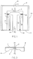
- the senor according to the present invention comprises a casing 10 which is preferably metallic and for example cylindrical and accommodates a membrane or diaphragm 1 which is suitable to be exposed to two pressures P1, P2 whose difference is to be measured.
- the casing 10 is provided with a base 11 and with a closure or cover 9 whereon it is possible to provide an optional opening 13 to allow one of the pressures (P1 in the figure) to access the diaphragm 1.
- a support or post 12 rises from the base 11 of the casing; the diaphragm 1, which accommodates a resonant element 2, is mounted on the support. Inside the post 12 there is provided a channel 14 for exposing the lower surface of the diaphragm 1 to the other one of the two pressures (P2 in the figure).
- the diaphragm 1 is constituted by a suitably machined silicon wafer and the resonant element 2 is formed at one of the two surfaces of the diaphragm.
- reinforcements designated by the reference numerals 15, 16, 17 and 18, which are fixed both to the post 12 and to the external structure.
- a resonant element 2 in the absence of pressure stresses on the faces, i.e., when the pressures on both faces of the diaphragm 1 are identical, a resonant element 2 can be made to vibrate with a suitable excitation system and has a resonance frequency of its own.
- the resonant element can be formed, for example, by a simple bar which is fixed to the diaphragm with its ends.
- the diaphragm 1 When the two faces of the diaphragm 1 are exposed to different pressures P1 and P2, the diaphragm flexes upward or downward according to the difference between the pressures. In these conditions, by means of its couplings to the diaphragm, the resonator 2 is subjected to elastic deformations (i.e., non-permanent deformations) causing compression or traction and its resonance frequency varies.
- elastic deformations i.e., non-permanent deformations
- a detection system senses the oscillations of the resonant element and provides a signal having the same frequency of the detected oscillations.
- the resonant element 2 is mounted at one of the faces of the diaphragm 1 in a cavity 7 formed on one of the two faces, and the cavity is kept in vacuum or in any case at a pressure of no more than 10 -2 torr.
- the resonator 2 is obtained from the diaphragm 1, keeping its ends rigidly coupled to the diaphragm, and the cavity 7 is closed hermetically (in vacuum or in any case at very low pressure) by a layer of silicon 8 which preferably covers the entire corresponding surface of the diaphragm.
- the embodiment shown schematically in figure 2 further includes a protection against overpressures.
- the resonator 2 is more sensitive to compressions, and an excessive difference in pressure (overpressure) when P1 > P2 might cause it to buckle.
- such diaphragm in order to limit the flexing of the diaphragm 1, such diaphragm is provided with a central protrusion or retainer 23 which protrudes from the lower surface 3 of the diaphragm 1 and is suitable to abut against a substrate 31 which is inserted between the post 12 and the diaphragm 1.
- the substrate 31 is joined to the edge of the diaphragm by means of a layer 25 of insulating material (preferably silicon oxide SiO 2 ), while in a downward region the substrate 21 is applied to the post by means of an annular layer 24 of insulating material (preferably pyrex).
- the protrusion 23 is formed monolithically with the diaphragm 1.
- the dimensions of the raised portion are chosen so as to avoid appreciably altering the elastic deformation characteristics of the diaphragm.
- the substrate-31 is relatively rigid and has a hole 32 for keeping the lower face of the diaphragm connected to the channel 14.
- the abutment surface of the protrusion 23 is arranged peripherally on a plane which is parallel to the plane of the membrane and to the plane of the substrate 31.
- Figure 4 illustrates the structure of a resonator 2 according to the present invention, which is formed by a balanced resonator which is capable of minimizing the constraint reactions caused by the oscillations of the resonator, thus reducing the effect of the damping actions at the coupling points between the resonator and the diaphragm.
- the resonator 2 is formed by two parallel tines or arms 21, 22 which are joined at their ends and is known as DETF (Double Ended Tuning Fork); its lateral vibrations, i.e., the vibrations which are perpendicular to the movement of the diaphragm and are designated by the arrows F in figure 4, are used.
- DETF Double Ended Tuning Fork
- the tines 21, 22 vibrate in phase opposition and at the constrained ends 24 the reactions to the motion of the two tines partially compensate each other, with a consequent lower dissipation of energy with respect to the case of a single vibrating prong.
- the balanced structure also allows several additional advantages, such as greater stability with respect to external influences, higher resolution, and reduction of the effect of long-term drifts.
- the DETF resonator is configured so as to have, at each end, two lateral protrusions 25 and a connecting portion 26 which are respectively wider and narrower than the central portion of the resonator. It is of course possible to use resonators with three or more parallel tines.
- the resonator 2 can be formed in various positions inside the diaphragm in order to achieve optimum sensitivity. More specifically, according to a first embodiment designated by the reference numeral 2B, it can be arranged substantially at the center of the diaphragm 1 and parallel to the plane of the diaphragm, in order to achieve maximum sensitivity. According to another embodiment, designated by the reference numeral 2A in figure 6, the resonator can be formed (or in any case positioned) at the edge of the diaphragm 1. This embodiment has lower sensitivity but offers the advantage of limiting the effects of overpressures.
- an additional sensing element which need not be provided in the same manner and according to the same principle as described above, can be integrated on the silicon membrane and allows to measure the common-mode pressure applied to the membrane.
- the resonator can be employed to measure the common-mode pressure by using a suitable electronic circuitry to detect the change of resistance of the resonator, said change being a consequence of the mechanical stress acting on the resonator itself and generated by the common-mode pressure.
- the device also has an excitation system for generating the oscillations of the resonator and a system for detecting them.
- the excitation and acquisition systems are of the electrostatic or piezoelectric type and have two armatures or electrodes 27 and 28 which are parallel to the arms 21 and 22 of the resonator 2 and are insulated from the resonator by means of insulating layers 29 and 30.
- the detection system is of piezoresistive type and the voltage signal is detected by terminals 31 e 32.
- the detection can be carried out, for example, using a bridge circuit connected to an electronic differential stage.
Landscapes
- Physics & Mathematics (AREA)
- General Physics & Mathematics (AREA)
- Measuring Fluid Pressure (AREA)
Applications Claiming Priority (2)
| Application Number | Priority Date | Filing Date | Title |
|---|---|---|---|
| ITMI962268 | 1996-10-31 | ||
| IT96MI002268A IT1287123B1 (it) | 1996-10-31 | 1996-10-31 | Dispositivo per la misura di una pressione |
Publications (3)
| Publication Number | Publication Date |
|---|---|
| EP0855583A2 true EP0855583A2 (fr) | 1998-07-29 |
| EP0855583A3 EP0855583A3 (fr) | 1999-03-24 |
| EP0855583B1 EP0855583B1 (fr) | 2002-07-24 |
Family
ID=11375132
Family Applications (1)
| Application Number | Title | Priority Date | Filing Date |
|---|---|---|---|
| EP97203360A Expired - Lifetime EP0855583B1 (fr) | 1996-10-31 | 1997-10-30 | Dispositif de mesure de pression |
Country Status (4)
| Country | Link |
|---|---|
| US (1) | US5969257A (fr) |
| EP (1) | EP0855583B1 (fr) |
| DE (1) | DE69714204T2 (fr) |
| IT (1) | IT1287123B1 (fr) |
Cited By (3)
| Publication number | Priority date | Publication date | Assignee | Title |
|---|---|---|---|---|
| US6207470B1 (en) * | 1997-09-18 | 2001-03-27 | Abb Kent Taylor S.P.A. | Method for manufacturing a pressure-measuring device equipped with a resonating element |
| US6584864B2 (en) | 2001-07-05 | 2003-07-01 | Druck Limited | Sensor |
| WO2010133861A1 (fr) * | 2009-05-21 | 2010-11-25 | Ge Infrastructure Sensing, Inc | Capteur |
Families Citing this family (12)
| Publication number | Priority date | Publication date | Assignee | Title |
|---|---|---|---|---|
| DE10314578A1 (de) * | 2003-03-31 | 2004-10-14 | Bosch Rexroth Ag | Hochfrequenzresonator |
| US7443509B1 (en) | 2004-12-12 | 2008-10-28 | Burns David W | Optical and electronic interface for optically coupled resonators |
| US7499604B1 (en) | 2004-12-12 | 2009-03-03 | Burns David W | Optically coupled resonant pressure sensor and process |
| US7176048B1 (en) | 2004-12-12 | 2007-02-13 | Burns David W | Optically coupled sealed-cavity resonator and process |
| US7379629B1 (en) | 2004-12-12 | 2008-05-27 | Burns David W | Optically coupled resonant pressure sensor |
| US7605391B2 (en) * | 2004-12-12 | 2009-10-20 | Burns David W | Optically coupled resonator |
| US20070236213A1 (en) * | 2006-03-30 | 2007-10-11 | Paden Bradley E | Telemetry method and apparatus using magnetically-driven mems resonant structure |
| JP4973718B2 (ja) * | 2009-01-27 | 2012-07-11 | セイコーエプソン株式会社 | 圧力検出ユニット、及び圧力センサー |
| WO2011036732A1 (fr) * | 2009-09-28 | 2011-03-31 | 株式会社 東芝 | Résonateur et oscillateur |
| US10197462B2 (en) * | 2016-05-25 | 2019-02-05 | Honeywell International Inc. | Differential pressure sensor full overpressure protection device |
| US10352800B2 (en) * | 2016-06-03 | 2019-07-16 | Mks Instruments, Inc. | Micromachined bulk acoustic wave resonator pressure sensor |
| JP6776143B2 (ja) * | 2017-02-03 | 2020-10-28 | 横河電機株式会社 | 水位計測システム |
Family Cites Families (9)
| Publication number | Priority date | Publication date | Assignee | Title |
|---|---|---|---|---|
| GB8418914D0 (en) * | 1984-07-25 | 1984-08-30 | Standard Telephones Cables Ltd | Transducer |
| US5062302A (en) * | 1988-04-29 | 1991-11-05 | Schlumberger Industries, Inc. | Laminated semiconductor sensor with overpressure protection |
| DE456029T1 (de) * | 1990-05-10 | 1992-06-11 | Yokogawa Electric Corp., Musashino, Tokio/Tokyo | Druckaufnehmer mit schwingendem element. |
| US5178015A (en) * | 1991-07-22 | 1993-01-12 | Monolithic Sensors Inc. | Silicon-on-silicon differential input sensors |
| US5275055A (en) * | 1992-08-31 | 1994-01-04 | Honeywell Inc. | Resonant gauge with microbeam driven in constant electric field |
| US5367217A (en) * | 1992-11-18 | 1994-11-22 | Alliedsignal Inc. | Four bar resonating force transducer |
| US5458000A (en) * | 1993-07-20 | 1995-10-17 | Honeywell Inc. | Static pressure compensation of resonant integrated microbeam sensors |
| DE4333099A1 (de) * | 1993-09-29 | 1995-03-30 | Bosch Gmbh Robert | Kraftsensor und Verfahren zur Herstellung eines Kraftsensors |
| US5528939A (en) * | 1995-03-21 | 1996-06-25 | Martin; Jacob H. | Micromechanical pressure gauge having extended sensor range |
-
1996
- 1996-10-31 IT IT96MI002268A patent/IT1287123B1/it active IP Right Grant
-
1997
- 1997-10-29 US US08/959,840 patent/US5969257A/en not_active Expired - Lifetime
- 1997-10-30 DE DE69714204T patent/DE69714204T2/de not_active Expired - Lifetime
- 1997-10-30 EP EP97203360A patent/EP0855583B1/fr not_active Expired - Lifetime
Cited By (4)
| Publication number | Priority date | Publication date | Assignee | Title |
|---|---|---|---|---|
| US6207470B1 (en) * | 1997-09-18 | 2001-03-27 | Abb Kent Taylor S.P.A. | Method for manufacturing a pressure-measuring device equipped with a resonating element |
| US6584864B2 (en) | 2001-07-05 | 2003-07-01 | Druck Limited | Sensor |
| WO2010133861A1 (fr) * | 2009-05-21 | 2010-11-25 | Ge Infrastructure Sensing, Inc | Capteur |
| US8863579B2 (en) | 2009-05-21 | 2014-10-21 | Ge Infrastructure Sensing, Inc. | Resonant sensor |
Also Published As
| Publication number | Publication date |
|---|---|
| EP0855583A3 (fr) | 1999-03-24 |
| DE69714204T2 (de) | 2003-03-27 |
| ITMI962268A1 (it) | 1998-05-01 |
| DE69714204D1 (de) | 2002-08-29 |
| IT1287123B1 (it) | 1998-08-04 |
| US5969257A (en) | 1999-10-19 |
| EP0855583B1 (fr) | 2002-07-24 |
Similar Documents
| Publication | Publication Date | Title |
|---|---|---|
| CN105606844B (zh) | 具有应变补偿的加速度计 | |
| US5233874A (en) | Active microaccelerometer | |
| US5969257A (en) | Pressure measuring membrane with resonant element vibrating orthogonal to membrane movement | |
| US5165289A (en) | Resonant mechanical sensor | |
| US6662658B2 (en) | Whiffletree accelerometer | |
| US7677105B2 (en) | Double-ended tuning fork type piezoelectric resonator and pressure sensor | |
| EP0740781B1 (fr) | Compensation pour capteurs a microfaisceaux resonnants integres | |
| EP0710357B1 (fr) | Microcapteur resonnant à isolation diélectrique | |
| US8297124B2 (en) | Pressure sensor | |
| US20030010123A1 (en) | Accelerometer | |
| JPH09502274A (ja) | 定電界で駆動されるマイクロビームによる共振ゲージ | |
| CN109883581B (zh) | 一种悬臂梁式差动谐振压力传感器芯片 | |
| KR20010032103A (ko) | 마이크로-기계적 차압 감응 장치 | |
| US20110100125A1 (en) | Acceleration sensor | |
| US5315874A (en) | Monolithic quartz resonator accelerometer | |
| US7017418B1 (en) | System and method for sensing pressure | |
| US5461918A (en) | Vibrating beam accelerometer | |
| JPS60186725A (ja) | 圧力センサ | |
| JPH02248866A (ja) | 加速度センサの梁構造 | |
| CN222635654U (zh) | 压电谐振式压力传感器及补偿系统 | |
| CN222635652U (zh) | 压电谐振式压力传感器及补偿系统 | |
| JPH0628662Y2 (ja) | 振動形差圧センサ | |
| EP1320735B1 (fr) | Dispositif permettant de mesurer la pression d'un fluide | |
| CN118624067B (zh) | 压电谐振式压力传感器、补偿系统及制备方法 | |
| GB2642076A (en) | Inertial sensors and methods of operation thereof |
Legal Events
| Date | Code | Title | Description |
|---|---|---|---|
| PUAI | Public reference made under article 153(3) epc to a published international application that has entered the european phase |
Free format text: ORIGINAL CODE: 0009012 |
|
| AK | Designated contracting states |
Kind code of ref document: A2 Designated state(s): DE ES FR GB IT |
|
| AX | Request for extension of the european patent |
Free format text: AL;LT;LV;RO;SI |
|
| PUAL | Search report despatched |
Free format text: ORIGINAL CODE: 0009013 |
|
| AK | Designated contracting states |
Kind code of ref document: A3 Designated state(s): AT BE CH DE DK ES FI FR GB GR IE IT LI LU MC NL PT SE |
|
| AX | Request for extension of the european patent |
Free format text: AL;LT;LV;RO;SI |
|
| AKX | Designation fees paid |
Free format text: DE ES FR GB IT |
|
| 17P | Request for examination filed |
Effective date: 19990913 |
|
| 17Q | First examination report despatched |
Effective date: 20000726 |
|
| GRAG | Despatch of communication of intention to grant |
Free format text: ORIGINAL CODE: EPIDOS AGRA |
|
| GRAG | Despatch of communication of intention to grant |
Free format text: ORIGINAL CODE: EPIDOS AGRA |
|
| GRAH | Despatch of communication of intention to grant a patent |
Free format text: ORIGINAL CODE: EPIDOS IGRA |
|
| GRAH | Despatch of communication of intention to grant a patent |
Free format text: ORIGINAL CODE: EPIDOS IGRA |
|
| GRAA | (expected) grant |
Free format text: ORIGINAL CODE: 0009210 |
|
| AK | Designated contracting states |
Kind code of ref document: B1 Designated state(s): DE ES FR GB IT |
|
| REG | Reference to a national code |
Ref country code: GB Ref legal event code: FG4D |
|
| REF | Corresponds to: |
Ref document number: 69714204 Country of ref document: DE Date of ref document: 20020829 |
|
| RAP2 | Party data changed (patent owner data changed or rights of a patent transferred) |
Owner name: ABB INSTRUMENTATION S.P.A. |
|
| ET | Fr: translation filed | ||
| PG25 | Lapsed in a contracting state [announced via postgrant information from national office to epo] |
Ref country code: ES Free format text: LAPSE BECAUSE OF FAILURE TO SUBMIT A TRANSLATION OF THE DESCRIPTION OR TO PAY THE FEE WITHIN THE PRESCRIBED TIME-LIMIT Effective date: 20030130 |
|
| PLBE | No opposition filed within time limit |
Free format text: ORIGINAL CODE: 0009261 |
|
| STAA | Information on the status of an ep patent application or granted ep patent |
Free format text: STATUS: NO OPPOSITION FILED WITHIN TIME LIMIT |
|
| 26N | No opposition filed |
Effective date: 20030425 |
|
| PGFP | Annual fee paid to national office [announced via postgrant information from national office to epo] |
Ref country code: FR Payment date: 20141022 Year of fee payment: 18 Ref country code: DE Payment date: 20141022 Year of fee payment: 18 Ref country code: GB Payment date: 20141021 Year of fee payment: 18 |
|
| PGFP | Annual fee paid to national office [announced via postgrant information from national office to epo] |
Ref country code: IT Payment date: 20141030 Year of fee payment: 18 |
|
| REG | Reference to a national code |
Ref country code: DE Ref legal event code: R082 Ref document number: 69714204 Country of ref document: DE Representative=s name: SCHAUMBURG UND PARTNER PATENTANWAELTE MBB, DE Ref country code: DE Ref legal event code: R082 Ref document number: 69714204 Country of ref document: DE Representative=s name: SCHAUMBURG & PARTNER PATENTANWAELTE MBB, DE Ref country code: DE Ref legal event code: R082 Ref document number: 69714204 Country of ref document: DE Representative=s name: SCHAUMBURG & PARTNER PATENTANWAELTE GBR, DE |
|
| REG | Reference to a national code |
Ref country code: DE Ref legal event code: R119 Ref document number: 69714204 Country of ref document: DE |
|
| GBPC | Gb: european patent ceased through non-payment of renewal fee |
Effective date: 20151030 |
|
| PG25 | Lapsed in a contracting state [announced via postgrant information from national office to epo] |
Ref country code: IT Free format text: LAPSE BECAUSE OF NON-PAYMENT OF DUE FEES Effective date: 20151030 Ref country code: GB Free format text: LAPSE BECAUSE OF NON-PAYMENT OF DUE FEES Effective date: 20151030 Ref country code: DE Free format text: LAPSE BECAUSE OF NON-PAYMENT OF DUE FEES Effective date: 20160503 |
|
| REG | Reference to a national code |
Ref country code: FR Ref legal event code: ST Effective date: 20160630 |
|
| PG25 | Lapsed in a contracting state [announced via postgrant information from national office to epo] |
Ref country code: FR Free format text: LAPSE BECAUSE OF NON-PAYMENT OF DUE FEES Effective date: 20151102 |