EP0855588B1 - Méthode de détection des ratés d'allumage normalisé - Google Patents
Méthode de détection des ratés d'allumage normalisé Download PDFInfo
- Publication number
- EP0855588B1 EP0855588B1 EP98100948A EP98100948A EP0855588B1 EP 0855588 B1 EP0855588 B1 EP 0855588B1 EP 98100948 A EP98100948 A EP 98100948A EP 98100948 A EP98100948 A EP 98100948A EP 0855588 B1 EP0855588 B1 EP 0855588B1
- Authority
- EP
- European Patent Office
- Prior art keywords
- pressure
- integral
- crankshaft
- engine
- piston
- Prior art date
- Legal status (The legal status is an assumption and is not a legal conclusion. Google has not performed a legal analysis and makes no representation as to the accuracy of the status listed.)
- Expired - Lifetime
Links
Images
Classifications
-
- G—PHYSICS
- G01—MEASURING; TESTING
- G01M—TESTING STATIC OR DYNAMIC BALANCE OF MACHINES OR STRUCTURES; TESTING OF STRUCTURES OR APPARATUS, NOT OTHERWISE PROVIDED FOR
- G01M15/00—Testing of engines
- G01M15/04—Testing internal-combustion engines
- G01M15/08—Testing internal-combustion engines by monitoring pressure in cylinders
-
- G—PHYSICS
- G01—MEASURING; TESTING
- G01M—TESTING STATIC OR DYNAMIC BALANCE OF MACHINES OR STRUCTURES; TESTING OF STRUCTURES OR APPARATUS, NOT OTHERWISE PROVIDED FOR
- G01M15/00—Testing of engines
- G01M15/04—Testing internal-combustion engines
- G01M15/11—Testing internal-combustion engines by detecting misfire
Definitions
- the present invention relates generally to an apparatus and method for detecting misfire in an internal combustion engine, and more particularly to an apparatus and method which detects the presence or absence of misfire utilizing engine cylinder pressure sensor data.
- a plurality of cylinders are operated through a four stage cycle which includes an intake stroke, a compression stroke, a power stroke and an exhaust stroke.
- a mixture of fuel and air is taken into a combustion chamber and compressed by a movable piston.
- a spark is generated by applying a high voltage to an ignition plug and the mixture is ignited and burned, thereby forcibly moving the piston and providing power.
- a partial or complete failure in causing the burning of the air/fuel mixture is called misfire.
- Adverse consequences of persistent misfire, whether partial or complete include a loss of engine power as well as an undesirable flow of fuel into the exhaust system.
- Various approaches for detecting misfire in internal combustion engines include monitoring engine crankshaft velocity, measuring the time between successive combustions, optically checking for the presence of ignition sparks, measuring exhaust gas temperature and monitoring the electrical characteristics of ignition signals.
- An additional approach that has been shown to be particularly effective involves measuring the pressure in each of the engine's combustion chambers. These pressure measurements are generally obtained using electronic pressure transducers mounted through a port in the combustion chamber which provide an electrical signal indicative of cylinder pressure. The pressure measurements obtained are compared to one or more predetermined thresholds below which misfire is presumed. This method, however, requires a high degree of accuracy in the pressure sensor readings which can be difficult to achieve in an environment such as an engine cylinder.
- Brosi et al. in U.S. Patent No. 5,020,360, as well as by Herden and Kusell in a related SAE paper entitled "A New Combustion Pressure Sensor for Advanced Engine Management", 1994. Brosi and Herden et al. provide compensation for subtle inaccuracies in sensitive pressure sensor data by calculating a difference pressure integral (dpi) rather than using absolute pressure measurements.
- dpi difference pressure integral
- This difference pressure integral begins with measurement of the pressure prevailing in the combustion chamber of an engine cylinder during the intake and compression strokes, prior to and without the influence of an ignition event.
- This "compression pressure” is measured as a function of the crankshaft angle, up to a crankshaft angle corresponding to the top dead center (TDC) position of the piston.
- TDC top dead center
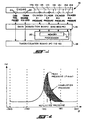
- the compression pressure data is reflected about a vertical line running through the top dead center point to produce a reflected pressure curve. (See FIG. 2).
- These reflected pressure values are stored in memory and subtracted from the combustion chamber pressure actually measured during the combustion and power strokes of engine operation to produce "combustion pressure" values, generally indicative of the incremental pressure increase in the chamber caused by the combustion of the air/fuel mixture.
- the combustion pressure values are then integrated over a predetermined range of crankshaft angles to produce the difference pressure integral. For resulting integral values that are extremely low or negative in sign, misfire is presumed.
- combustion pressures obtained necessarily depend upon the speed and loading of the engine.
- combustion pressure, and therefore the difference pressure integral are usually greater at higher loads and less in light loads such as during engine idle.
- a number of difference pressure integral thresholds can be required, with a different threshold being employed at each load level.
- the present invention removes the influence of engine speed and/or loading by normalizing the difference pressure integral. By dividing the difference pressure integral by the maximum combustion chamber pressure reached after TDC, the variance due to load is substantially eliminated.
- the present invention provides an improved engine misfire detection method which minimizes the effects of pressure sensor inaccuracies while being operable over a wide range of speeds and engine loads. Both partial and complete misfires are readily detectable utilizing a single threshold. This is especially useful in implementations on-board a vehicle wherein it is desirable to detect and control misfire in real time while consuming a minimum of computer power.
- a misfire detection system for carrying out the method of the present invention on a four-cylinder internal combustion engine is indicated generally at 10.
- a four-cylinder engine is utilized herein for purposes of illustration, it should be readily appreciable that the present invention is equally well suited for use in conjunction with an engine having any number of cylinders and on any number of, or all of, an engine's cylinders.
- the present invention is also readily adaptable for use with two-stroke as well as four-stroke engines.
- System 10 includes four cylinder pressure sensors 12a-12d, one being mounted to each of the four engine cylinders 14a-14d in a suitable manner. While any sensor suitable for producing an electrical signal indicative of cylinder pressure may be used, sensors 12a-12d are preferably of a type disclosed in U.S. Patent No. 5,559,280 to Kovacich et al., assigned to the assignee of the present invention. Sensors of this type are pressure transducers mounted through a port formed in the combustion chamber such as a threaded hole in the cylinder head.
- These sensors generally include a pressure responsive member operable in response to sensed pressure in the combustion chamber to contact a piezoresistive beam which causes a series of piezoresistors to generate an electrical signal which is indicative of pressure forces on the member and thereby indicative of combustion chamber pressure.
- Each pressure sensor 12 is electrically coupled to a data acquisition board 16, such as that commonly commercially available from National Instruments, model DHS 180 2HC .
- Board 16 has included therein or coupled thereto, a memory or data storage device 18 having a plurality of data memory locations for storing pressure data obtained from pressure sensors 12 as well as for holding intermediate values generated in the calculation process.
- a connected microprocessor 20 is performed by a connected microprocessor 20.
- processor 20 is preferably mounted on-board the vehicle but measurement data obtained by sensors 12 could alternately be stored for later off-board processing.
- pulses indicative of the instantaneous angular position of the crankshaft are obtained from a crankshaft angle sensor 22 in a manner well known to those of skill in the art.
- the crankshaft angle readings are sent to board 16 as are pulses indicating the top dead center (TDC) position of the piston, obtained from a one pulse per revolution sensor 24, such as a hall effect sensor, also sent to a timer/counter board 26, such as that commonly commercially available from National Instruments, model PC-T10-10.
- Each pressure reading obtained from a pressure sensor 12 is associated in memory 18 with the crankshaft angle at which the pressure reading was taken. In the presently preferred embodiment of the present invention, a pressure measurement is obtained or sampled at each degree of increasing crankshaft angle, but any other suitable increment may alternately be used.
- combustion chamber pressure P ⁇
- compression pressure occurring at crankshaft angles prior to top dead center is produced in the combustion chamber by the motion of the piston inside the cylinder prior to ignition.
- the engine is acting as a compressor, compressing the air/fuel mixture for ignition. This pressure is measured by system 10 at increasing crankshaft angles up until the top dead center of the piston is reached.
- each pressure measurement is stored in a memory location associated with a predetermined crankshaft angle and for crankshaft angles above that at which the piston reaches top dead center, the measured compression pressure values are utilized in a reverse order or, alternately, stored in additional memory locations, each associated with a crankshaft angle greater than that obtained at top dead center.
- combustion pressure From the actual combustion chamber pressure measurements obtained by sensors 12 during the combustion and exhaust strokes of the engine and the reflected compression pressure values, a "combustion pressure" can be determined. At each crankshaft angle ( ⁇ ) past the top dead center point, the reflected pressure value corresponding to that angle is subtracted from the actual combustion chamber pressure measurement occurring at the same crankshaft angle. Since the reflected pressures are simply the compression pressures utilized in reverse order, this combustion pressure can be expressed as (P ⁇ - P (TDC- ⁇ ) ).
- this method provides an effective way for detecting misfire as well as a method for controlling engine firing via adjustments in the crankshaft firing angle based on the difference pressure integral obtained, this method in and of itself can be sensitive to engine load levels. While generally able to detect complete engine misfires, detecting partial misfires, especially at low load conditions such as when an engine is near an idling state, has proven to be more difficult.
- the system and method of the present invention provides a way to normalize the difference pressure integral, in order to make it much less sensitive to load. This also enables a single threshold value to be set which can be used to effectively identify and control partial as well as complete misfire over varying engine load levels.
- this normalized difference pressure integral value is made insensitive to engine load levels and thereby enables the setting of a threshold level, below which either total or partial misfire is indicated.
- the factor N is optionally applied in order to produce resulting dp andi values in a desired and convenient range. N may therefore be unity or any real number or integer.
- this threshold is generally in the range of 0 to 50% of a maximum dp andi.
- a range in ⁇ for dp andi calculation is (TDC + 180°) as indicated above, but any other suitable range of angles could alternately be used.
- this range in crankshaft angles is preferably chosen so as to encompass the entire power stroke of the engine but not so large as to include the next intake and/or compression strokes.
- a single misfire detection threshold can be selected.
- the threshold is preferably set so as to fall below the lowest expected normal dp andi value. This threshold can be set higher to catch more minor partial misfires or lower to catch only more complete misfires, depending upon the desired functionality and accuracy of the misfire detection system.
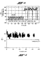
- the normalization of the difference pressure integral results in a nearly constant range of dp andi values irrespective of engine speed and loads. This enables a single threshold to be set, as opposed to necessitating a different threshold level for each different operating condition of the engine, as would be required with dp andi values which are not normalized in accordance with the present method, as illustrated in Figure 3. This capability is especially valuable in vehicular applications where misfire is to be detected in real-time for up to 8 or more cylinders simultaneously, under varying engine loads as typically occur in normal driving conditions.
- the normalized difference pressure integral data obtained using the present invention can also be further utilized to control the engine in a manner similar to that taught by Brosi, or by any other suitable method.
Landscapes
- Chemical & Material Sciences (AREA)
- Engineering & Computer Science (AREA)
- Combustion & Propulsion (AREA)
- Physics & Mathematics (AREA)
- General Physics & Mathematics (AREA)
- Combined Controls Of Internal Combustion Engines (AREA)
Claims (10)
- Procédé de détection des ratés dans un moteur à combustion interne comprenant les étapes consistant à :obtenir une série de mesures de pression dans au moins une chambre de combustion dudit moteur, chaque dite mesure étant associée à un angle croissant de manière incrémentielle de vilebrequin ;générer une série de valeurs reflétées de pression de compression en utilisant lesdites mesures de pression obtenues à des angles de vilebrequin avant la position du point mort haut du piston qui se déplace dans ladite chambre de combustion, dans l'ordre inverse pour des angles après la position du point mort haut dudit piston ;intégrer les différences entre lesdites mesures de pression et lesdites valeurs reflétées de pression de compression sur une plage d'angles de vilebrequin ;diviser l'intégrale obtenue par la mesure la plus grande desdites mesures de pression obtenues ;définir un seuil ; etcomparer ladite intégrale normalisée audit seuil dans lequel un raté est détecté lorsque ladite intégrale normalisée tombe en dessous dudit seuil.
- Procédé selon la revendication 1, comprenant, en outre, l'étape consistant à multiplier ladite intégrale par un facteur prédéterminé.
- Procédé selon la revendication 2, dans lequel ledit facteur est un nombre entier.
- Procédé selon la revendication 1, dans lequel ledit procédé est employé dans une application de véhicule automobile et ledit niveau du seuil est établi entre 0 et 50 % d'une valeur d'intégrale de pression normalisée attendue maximale.
- Procédé selon la revendication 1, dans lequel ledit procédé est employé dans une application de véhicule automobile et ledit niveau du seuil est établi pour être inférieur à une valeur d'intégrale de pression normalisée attendue minimale.
- Procédé selon la revendication 1, dans lequel la mesure de pression la plus grande est ladite mesure la plus grande obtenue à l'intérieur de 60° de ladite position de point mort haut.
- Procédé selon la revendication 1, dans lequel ladite plage des angles de vilebrequin commence avec l'angle à ladite position de point mort haut dudit piston.
- Procédé selon la revendication 7, dans lequel ladite plage des angles de vilebrequin s'étend sur 180°.
- Système pour détecter des ratés dans un moteur à combustion interne comportant un piston qui se déplace à l'intérieur d'un cylindre, ledit système utilisant le procédé de la revendication 1 et comprenant :un transducteur de pression disposé par rapport audit cylindre de façon à délivrer un signal électrique indicatif de la pression dans ledit cylindre ;un capteur d'angle de vilebrequin conçu pour produire un signal électrique indicatif d'un angle instantané d'un vilebrequin accouplé audit piston ;un dispositif de mémoire conçu pour mémoriser les mesures de pression obtenues par ledit transducteur haute pression, chaque dite mesure étant associée à une mesure de l'angle de vilebrequin instantané, ledit dispositif de mémoire étant également conçu pour mémoriser une série de valeurs reflétées de pression ; etun procédé électrique couplé audit dispositif de mémoire pour intégrer la différence entre lesdites mesures de pression et lesdites valeurs reflétées de pression sur une plage prédéfinie d'angles de vilebrequin et pour normaliser ladite intégrale en divisant ladite intégrale par la valeur maximale de pression mémorisée dans ladite mémoire.
- Système selon la revendication 9, dans lequel ledit système est mis en oeuvre à bord d'un véhicule automobile.
Applications Claiming Priority (2)
| Application Number | Priority Date | Filing Date | Title |
|---|---|---|---|
| US08/789,034 US5758307A (en) | 1997-01-27 | 1997-01-27 | Normalized misfire detection method |
| US789034 | 1997-01-27 |
Publications (2)
| Publication Number | Publication Date |
|---|---|
| EP0855588A1 EP0855588A1 (fr) | 1998-07-29 |
| EP0855588B1 true EP0855588B1 (fr) | 2003-06-11 |
Family
ID=25146376
Family Applications (1)
| Application Number | Title | Priority Date | Filing Date |
|---|---|---|---|
| EP98100948A Expired - Lifetime EP0855588B1 (fr) | 1997-01-27 | 1998-01-21 | Méthode de détection des ratés d'allumage normalisé |
Country Status (3)
| Country | Link |
|---|---|
| US (1) | US5758307A (fr) |
| EP (1) | EP0855588B1 (fr) |
| DE (1) | DE69815409T2 (fr) |
Families Citing this family (9)
| Publication number | Priority date | Publication date | Assignee | Title |
|---|---|---|---|---|
| US6367317B1 (en) * | 2000-02-24 | 2002-04-09 | Daimlerchrysler Corporation | Algorithm for determining the top dead center location in an internal combustion engine using cylinder pressure measurements |
| EP2479412A3 (fr) * | 2001-03-30 | 2014-08-13 | Mitsubishi Heavy Industries, Ltd. | Appareil et procédé de contrôle/diagnostic de la combustion d'un moteur à combustion interne |
| US7624718B2 (en) * | 2004-02-02 | 2009-12-01 | Yamaha Hatsudoki Kabushiki Kaisha | Engine control system, vehicle having the same, method for calculating combustion center of gravity, and method for controlling engine |
| KR100579926B1 (ko) * | 2004-06-30 | 2006-05-15 | 현대자동차주식회사 | 내연기관의 실화 판정 방법 및 시스템 |
| JP4509986B2 (ja) * | 2005-12-27 | 2010-07-21 | 本田技研工業株式会社 | 内燃機関の失火検出装置 |
| US10436676B2 (en) | 2011-08-10 | 2019-10-08 | Thompson Automotive Labs Llc | Method and apparatus for engine analysis and remote engine analysis |
| US9279406B2 (en) | 2012-06-22 | 2016-03-08 | Illinois Tool Works, Inc. | System and method for analyzing carbon build up in an engine |
| SE542026C2 (en) * | 2018-06-25 | 2020-02-11 | Scania Cv Ab | Method and control device for determining reliability regarding misfire determination of cylinders of an internal combustion engine |
| US10934965B2 (en) | 2019-04-05 | 2021-03-02 | Woodward, Inc. | Auto-ignition control in a combustion engine |
Family Cites Families (17)
| Publication number | Priority date | Publication date | Assignee | Title |
|---|---|---|---|---|
| US4050296A (en) * | 1976-05-07 | 1977-09-27 | United Technologies Corporation | Relative compression of an internal combustion engine |
| DE2655064A1 (de) * | 1976-12-04 | 1978-06-08 | Daimler Benz Ag | Verfahren und vorrichtung zur festlegung des oberen totpunktes bei kolbenmaschinen |
| US4539841A (en) * | 1984-02-13 | 1985-09-10 | General Motors Corporation | Method of determining engine cylinder compression pressure and power output |
| US5153834A (en) * | 1986-09-10 | 1992-10-06 | Nissan Motor Co., Ltd. | Method and apparatus for detecting a misfire in a combustion chamber of an internal combustion engine |
| DE3736430A1 (de) * | 1987-10-28 | 1989-05-11 | Bosch Gmbh Robert | Verfahren zur regelung des zuendwinkels bei einer brennkraftmaschine |
| US4892075A (en) * | 1987-11-02 | 1990-01-09 | Nissan Motor Co., Ltd. | Crank angle detecting system for internal combustion engines |
| KR920006456B1 (ko) * | 1988-03-08 | 1992-08-06 | 미쓰비시전기 주식회사 | 통내압 검출장치 |
| DE3835285A1 (de) * | 1988-10-15 | 1990-04-19 | Bosch Gmbh Robert | Verfahren und vorrichtung zur zuendaussetzerkennung |
| DE69125194T2 (de) * | 1990-01-09 | 1997-07-17 | Atsugi Unisia Corp | Verfahren und Vorrichtung zur Detektierung eines Verbrennungsdefekts in einem Zylinder einer inneren Brennkraftmaschine |
| DE4126782C2 (de) * | 1990-08-13 | 2001-02-15 | Mitsubishi Electric Corp | Gerät und Verfahren zur Erfassung von Fehlzündungen bei einem Verbrennungsmotor |
| DE59201787D1 (de) * | 1991-01-24 | 1995-05-04 | Siemens Ag | Einrichtung zum erkennen von mangelhaften verbrennungen in einer brennkraftmaschine. |
| US5193513A (en) * | 1992-06-03 | 1993-03-16 | Ford Motor Company | Misfire detection in an internal combustion engine using exhaust pressure |
| US5415036A (en) * | 1994-01-28 | 1995-05-16 | Kavlico Corporation | Automotive misfire cylinder identification system |
| JPH07286551A (ja) * | 1994-04-15 | 1995-10-31 | Unisia Jecs Corp | 内燃機関の失火検出装置 |
| US5559280A (en) * | 1994-11-14 | 1996-09-24 | Eaton Corporation | Combustion chamber pressure transducer and method of making same |
| JP3194680B2 (ja) * | 1994-12-15 | 2001-07-30 | 三菱電機株式会社 | 内燃機関の失火検出装置 |
| US5574217A (en) * | 1995-06-06 | 1996-11-12 | Chrysler Corporation | Engine misfire detection with compensation for normal acceleration of crankshaft |
-
1997
- 1997-01-27 US US08/789,034 patent/US5758307A/en not_active Expired - Fee Related
-
1998
- 1998-01-21 DE DE69815409T patent/DE69815409T2/de not_active Expired - Fee Related
- 1998-01-21 EP EP98100948A patent/EP0855588B1/fr not_active Expired - Lifetime
Also Published As
| Publication number | Publication date |
|---|---|
| DE69815409T2 (de) | 2004-05-13 |
| DE69815409D1 (de) | 2003-07-17 |
| EP0855588A1 (fr) | 1998-07-29 |
| US5758307A (en) | 1998-05-26 |
Similar Documents
| Publication | Publication Date | Title |
|---|---|---|
| US5915272A (en) | Method of detecting low compression pressure responsive to crankshaft acceleration measurement and apparatus therefor | |
| US6935313B2 (en) | System and method for diagnosing and calibrating internal combustion engines | |
| US5934256A (en) | Method for detecting irregular combustion processes in a multicylinder diesel internal combustion engine | |
| US6276319B2 (en) | Method for evaluating the march of pressure in a combustion chamber | |
| US5263364A (en) | Apparatus for detecting misfire in multicylinder internal combustion engines | |
| US6876919B2 (en) | Cylinder specific performance parameter computed for an internal combustion engine | |
| US5935189A (en) | System and method for monitoring engine performance characteristics | |
| US5351528A (en) | Apparatus and method for detecting misfiring in an internal combustion engine | |
| GB2210930A (en) | Variable compression ratio i.c. engine | |
| US6091244A (en) | Method and arrangement for detecting combustion misfires of a internal combustion engine | |
| US7455047B2 (en) | Control unit for an internal combustion engine | |
| JP6844098B2 (ja) | 大型低速エンジンの燃焼分析装置及びこれを利用したエンジンの燃焼状態判断方法 | |
| US5020360A (en) | Process for determining and evaluating the combustion pressure of an internal combustion engine | |
| US5493901A (en) | Combustion state-detecting system for internal combustion engines | |
| US5758307A (en) | Normalized misfire detection method | |
| JP3466207B2 (ja) | 動作行程識別方法および識別装置 | |
| CN1214758A (zh) | 用于识别一个多缸柴油发动机中的不规则的燃烧过程的方法 | |
| US5492007A (en) | Misfire detection in a spark ignition engine | |
| US5415035A (en) | Combustion state-detecting system for internal combustion engines | |
| US9322382B2 (en) | Method for detecting detonation phenomena in an internal combustion engine | |
| US5503007A (en) | Misfire detection method and apparatus therefor | |
| US5528930A (en) | Engine misfire detection system and method | |
| US20060116812A1 (en) | Combustion state detecting apparatus for an engine | |
| GB2301898A (en) | Detecting engine cylinder misfire | |
| US5571958A (en) | Apparatus and method for detecting misfire in an internal combustion engine |
Legal Events
| Date | Code | Title | Description |
|---|---|---|---|
| PUAI | Public reference made under article 153(3) epc to a published international application that has entered the european phase |
Free format text: ORIGINAL CODE: 0009012 |
|
| AK | Designated contracting states |
Kind code of ref document: A1 Designated state(s): DE FR GB |
|
| AX | Request for extension of the european patent |
Free format text: AL;LT;LV;MK;RO;SI |
|
| 17P | Request for examination filed |
Effective date: 19981031 |
|
| AKX | Designation fees paid |
Free format text: DE FR GB |
|
| RBV | Designated contracting states (corrected) |
Designated state(s): DE FR GB |
|
| 17Q | First examination report despatched |
Effective date: 20011025 |
|
| RAP1 | Party data changed (applicant data changed or rights of an application transferred) |
Owner name: DELPHI TECHNOLOGIES, INC. |
|
| GRAH | Despatch of communication of intention to grant a patent |
Free format text: ORIGINAL CODE: EPIDOS IGRA |
|
| RAP1 | Party data changed (applicant data changed or rights of an application transferred) |
Owner name: DELPHI TECHNOLOGIES, INC. |
|
| GRAH | Despatch of communication of intention to grant a patent |
Free format text: ORIGINAL CODE: EPIDOS IGRA |
|
| GRAA | (expected) grant |
Free format text: ORIGINAL CODE: 0009210 |
|
| AK | Designated contracting states |
Designated state(s): DE FR GB |
|
| REG | Reference to a national code |
Ref country code: GB Ref legal event code: FG4D |
|
| REF | Corresponds to: |
Ref document number: 69815409 Country of ref document: DE Date of ref document: 20030717 Kind code of ref document: P |
|
| ET | Fr: translation filed | ||
| PG25 | Lapsed in a contracting state [announced via postgrant information from national office to epo] |
Ref country code: GB Free format text: LAPSE BECAUSE OF NON-PAYMENT OF DUE FEES Effective date: 20040121 |
|
| PGFP | Annual fee paid to national office [announced via postgrant information from national office to epo] |
Ref country code: FR Payment date: 20040131 Year of fee payment: 7 Ref country code: DE Payment date: 20040131 Year of fee payment: 7 |
|
| PLBE | No opposition filed within time limit |
Free format text: ORIGINAL CODE: 0009261 |
|
| STAA | Information on the status of an ep patent application or granted ep patent |
Free format text: STATUS: NO OPPOSITION FILED WITHIN TIME LIMIT |
|
| 26N | No opposition filed |
Effective date: 20040312 |
|
| GBPC | Gb: european patent ceased through non-payment of renewal fee |
Effective date: 20040121 |
|
| PG25 | Lapsed in a contracting state [announced via postgrant information from national office to epo] |
Ref country code: DE Free format text: LAPSE BECAUSE OF NON-PAYMENT OF DUE FEES Effective date: 20050802 |
|
| PG25 | Lapsed in a contracting state [announced via postgrant information from national office to epo] |
Ref country code: FR Free format text: LAPSE BECAUSE OF NON-PAYMENT OF DUE FEES Effective date: 20050930 |
|
| REG | Reference to a national code |
Ref country code: FR Ref legal event code: ST |