EP0855691A1 - Panneau d'affichage à plasma - Google Patents
Panneau d'affichage à plasma Download PDFInfo
- Publication number
- EP0855691A1 EP0855691A1 EP97306454A EP97306454A EP0855691A1 EP 0855691 A1 EP0855691 A1 EP 0855691A1 EP 97306454 A EP97306454 A EP 97306454A EP 97306454 A EP97306454 A EP 97306454A EP 0855691 A1 EP0855691 A1 EP 0855691A1
- Authority
- EP
- European Patent Office
- Prior art keywords
- electrodes
- numbered
- odd
- discharge
- sustain
- Prior art date
- Legal status (The legal status is an assumption and is not a legal conclusion. Google has not performed a legal analysis and makes no representation as to the accuracy of the status listed.)
- Granted
Links
Images


Classifications
-
- G—PHYSICS
- G09—EDUCATION; CRYPTOGRAPHY; DISPLAY; ADVERTISING; SEALS
- G09G—ARRANGEMENTS OR CIRCUITS FOR CONTROL OF INDICATING DEVICES USING STATIC MEANS TO PRESENT VARIABLE INFORMATION
- G09G3/00—Control arrangements or circuits, of interest only in connection with visual indicators other than cathode-ray tubes
- G09G3/20—Control arrangements or circuits, of interest only in connection with visual indicators other than cathode-ray tubes for presentation of an assembly of a number of characters, e.g. a page, by composing the assembly by combination of individual elements arranged in a matrix no fixed position being assigned to or needed to be assigned to the individual characters or partial characters
- G09G3/22—Control arrangements or circuits, of interest only in connection with visual indicators other than cathode-ray tubes for presentation of an assembly of a number of characters, e.g. a page, by composing the assembly by combination of individual elements arranged in a matrix no fixed position being assigned to or needed to be assigned to the individual characters or partial characters using controlled light sources
- G09G3/28—Control arrangements or circuits, of interest only in connection with visual indicators other than cathode-ray tubes for presentation of an assembly of a number of characters, e.g. a page, by composing the assembly by combination of individual elements arranged in a matrix no fixed position being assigned to or needed to be assigned to the individual characters or partial characters using controlled light sources using luminous gas-discharge panels, e.g. plasma panels
- G09G3/288—Control arrangements or circuits, of interest only in connection with visual indicators other than cathode-ray tubes for presentation of an assembly of a number of characters, e.g. a page, by composing the assembly by combination of individual elements arranged in a matrix no fixed position being assigned to or needed to be assigned to the individual characters or partial characters using controlled light sources using luminous gas-discharge panels, e.g. plasma panels using AC panels
- G09G3/291—Control arrangements or circuits, of interest only in connection with visual indicators other than cathode-ray tubes for presentation of an assembly of a number of characters, e.g. a page, by composing the assembly by combination of individual elements arranged in a matrix no fixed position being assigned to or needed to be assigned to the individual characters or partial characters using controlled light sources using luminous gas-discharge panels, e.g. plasma panels using AC panels controlling the gas discharge to control a cell condition, e.g. by means of specific pulse shapes
- G09G3/292—Control arrangements or circuits, of interest only in connection with visual indicators other than cathode-ray tubes for presentation of an assembly of a number of characters, e.g. a page, by composing the assembly by combination of individual elements arranged in a matrix no fixed position being assigned to or needed to be assigned to the individual characters or partial characters using controlled light sources using luminous gas-discharge panels, e.g. plasma panels using AC panels controlling the gas discharge to control a cell condition, e.g. by means of specific pulse shapes for reset discharge, priming discharge or erase discharge occurring in a phase other than addressing
- G09G3/2927—Details of initialising
-
- G—PHYSICS
- G09—EDUCATION; CRYPTOGRAPHY; DISPLAY; ADVERTISING; SEALS
- G09G—ARRANGEMENTS OR CIRCUITS FOR CONTROL OF INDICATING DEVICES USING STATIC MEANS TO PRESENT VARIABLE INFORMATION
- G09G3/00—Control arrangements or circuits, of interest only in connection with visual indicators other than cathode-ray tubes
- G09G3/20—Control arrangements or circuits, of interest only in connection with visual indicators other than cathode-ray tubes for presentation of an assembly of a number of characters, e.g. a page, by composing the assembly by combination of individual elements arranged in a matrix no fixed position being assigned to or needed to be assigned to the individual characters or partial characters
- G09G3/22—Control arrangements or circuits, of interest only in connection with visual indicators other than cathode-ray tubes for presentation of an assembly of a number of characters, e.g. a page, by composing the assembly by combination of individual elements arranged in a matrix no fixed position being assigned to or needed to be assigned to the individual characters or partial characters using controlled light sources
- G09G3/28—Control arrangements or circuits, of interest only in connection with visual indicators other than cathode-ray tubes for presentation of an assembly of a number of characters, e.g. a page, by composing the assembly by combination of individual elements arranged in a matrix no fixed position being assigned to or needed to be assigned to the individual characters or partial characters using controlled light sources using luminous gas-discharge panels, e.g. plasma panels
- G09G3/288—Control arrangements or circuits, of interest only in connection with visual indicators other than cathode-ray tubes for presentation of an assembly of a number of characters, e.g. a page, by composing the assembly by combination of individual elements arranged in a matrix no fixed position being assigned to or needed to be assigned to the individual characters or partial characters using controlled light sources using luminous gas-discharge panels, e.g. plasma panels using AC panels
- G09G3/291—Control arrangements or circuits, of interest only in connection with visual indicators other than cathode-ray tubes for presentation of an assembly of a number of characters, e.g. a page, by composing the assembly by combination of individual elements arranged in a matrix no fixed position being assigned to or needed to be assigned to the individual characters or partial characters using controlled light sources using luminous gas-discharge panels, e.g. plasma panels using AC panels controlling the gas discharge to control a cell condition, e.g. by means of specific pulse shapes
- G09G3/293—Control arrangements or circuits, of interest only in connection with visual indicators other than cathode-ray tubes for presentation of an assembly of a number of characters, e.g. a page, by composing the assembly by combination of individual elements arranged in a matrix no fixed position being assigned to or needed to be assigned to the individual characters or partial characters using controlled light sources using luminous gas-discharge panels, e.g. plasma panels using AC panels controlling the gas discharge to control a cell condition, e.g. by means of specific pulse shapes for address discharge
- G09G3/2932—Addressed by writing selected cells that are in an OFF state
-
- G—PHYSICS
- G09—EDUCATION; CRYPTOGRAPHY; DISPLAY; ADVERTISING; SEALS
- G09G—ARRANGEMENTS OR CIRCUITS FOR CONTROL OF INDICATING DEVICES USING STATIC MEANS TO PRESENT VARIABLE INFORMATION
- G09G3/00—Control arrangements or circuits, of interest only in connection with visual indicators other than cathode-ray tubes
- G09G3/20—Control arrangements or circuits, of interest only in connection with visual indicators other than cathode-ray tubes for presentation of an assembly of a number of characters, e.g. a page, by composing the assembly by combination of individual elements arranged in a matrix no fixed position being assigned to or needed to be assigned to the individual characters or partial characters
- G09G3/22—Control arrangements or circuits, of interest only in connection with visual indicators other than cathode-ray tubes for presentation of an assembly of a number of characters, e.g. a page, by composing the assembly by combination of individual elements arranged in a matrix no fixed position being assigned to or needed to be assigned to the individual characters or partial characters using controlled light sources
- G09G3/28—Control arrangements or circuits, of interest only in connection with visual indicators other than cathode-ray tubes for presentation of an assembly of a number of characters, e.g. a page, by composing the assembly by combination of individual elements arranged in a matrix no fixed position being assigned to or needed to be assigned to the individual characters or partial characters using controlled light sources using luminous gas-discharge panels, e.g. plasma panels
- G09G3/288—Control arrangements or circuits, of interest only in connection with visual indicators other than cathode-ray tubes for presentation of an assembly of a number of characters, e.g. a page, by composing the assembly by combination of individual elements arranged in a matrix no fixed position being assigned to or needed to be assigned to the individual characters or partial characters using controlled light sources using luminous gas-discharge panels, e.g. plasma panels using AC panels
- G09G3/291—Control arrangements or circuits, of interest only in connection with visual indicators other than cathode-ray tubes for presentation of an assembly of a number of characters, e.g. a page, by composing the assembly by combination of individual elements arranged in a matrix no fixed position being assigned to or needed to be assigned to the individual characters or partial characters using controlled light sources using luminous gas-discharge panels, e.g. plasma panels using AC panels controlling the gas discharge to control a cell condition, e.g. by means of specific pulse shapes
- G09G3/294—Control arrangements or circuits, of interest only in connection with visual indicators other than cathode-ray tubes for presentation of an assembly of a number of characters, e.g. a page, by composing the assembly by combination of individual elements arranged in a matrix no fixed position being assigned to or needed to be assigned to the individual characters or partial characters using controlled light sources using luminous gas-discharge panels, e.g. plasma panels using AC panels controlling the gas discharge to control a cell condition, e.g. by means of specific pulse shapes for lighting or sustain discharge
-
- G—PHYSICS
- G09—EDUCATION; CRYPTOGRAPHY; DISPLAY; ADVERTISING; SEALS
- G09G—ARRANGEMENTS OR CIRCUITS FOR CONTROL OF INDICATING DEVICES USING STATIC MEANS TO PRESENT VARIABLE INFORMATION
- G09G3/00—Control arrangements or circuits, of interest only in connection with visual indicators other than cathode-ray tubes
- G09G3/20—Control arrangements or circuits, of interest only in connection with visual indicators other than cathode-ray tubes for presentation of an assembly of a number of characters, e.g. a page, by composing the assembly by combination of individual elements arranged in a matrix no fixed position being assigned to or needed to be assigned to the individual characters or partial characters
- G09G3/22—Control arrangements or circuits, of interest only in connection with visual indicators other than cathode-ray tubes for presentation of an assembly of a number of characters, e.g. a page, by composing the assembly by combination of individual elements arranged in a matrix no fixed position being assigned to or needed to be assigned to the individual characters or partial characters using controlled light sources
- G09G3/28—Control arrangements or circuits, of interest only in connection with visual indicators other than cathode-ray tubes for presentation of an assembly of a number of characters, e.g. a page, by composing the assembly by combination of individual elements arranged in a matrix no fixed position being assigned to or needed to be assigned to the individual characters or partial characters using controlled light sources using luminous gas-discharge panels, e.g. plasma panels
- G09G3/288—Control arrangements or circuits, of interest only in connection with visual indicators other than cathode-ray tubes for presentation of an assembly of a number of characters, e.g. a page, by composing the assembly by combination of individual elements arranged in a matrix no fixed position being assigned to or needed to be assigned to the individual characters or partial characters using controlled light sources using luminous gas-discharge panels, e.g. plasma panels using AC panels
- G09G3/296—Driving circuits for producing the waveforms applied to the driving electrodes
-
- G—PHYSICS
- G09—EDUCATION; CRYPTOGRAPHY; DISPLAY; ADVERTISING; SEALS
- G09G—ARRANGEMENTS OR CIRCUITS FOR CONTROL OF INDICATING DEVICES USING STATIC MEANS TO PRESENT VARIABLE INFORMATION
- G09G3/00—Control arrangements or circuits, of interest only in connection with visual indicators other than cathode-ray tubes
- G09G3/20—Control arrangements or circuits, of interest only in connection with visual indicators other than cathode-ray tubes for presentation of an assembly of a number of characters, e.g. a page, by composing the assembly by combination of individual elements arranged in a matrix no fixed position being assigned to or needed to be assigned to the individual characters or partial characters
- G09G3/22—Control arrangements or circuits, of interest only in connection with visual indicators other than cathode-ray tubes for presentation of an assembly of a number of characters, e.g. a page, by composing the assembly by combination of individual elements arranged in a matrix no fixed position being assigned to or needed to be assigned to the individual characters or partial characters using controlled light sources
- G09G3/28—Control arrangements or circuits, of interest only in connection with visual indicators other than cathode-ray tubes for presentation of an assembly of a number of characters, e.g. a page, by composing the assembly by combination of individual elements arranged in a matrix no fixed position being assigned to or needed to be assigned to the individual characters or partial characters using controlled light sources using luminous gas-discharge panels, e.g. plasma panels
- G09G3/288—Control arrangements or circuits, of interest only in connection with visual indicators other than cathode-ray tubes for presentation of an assembly of a number of characters, e.g. a page, by composing the assembly by combination of individual elements arranged in a matrix no fixed position being assigned to or needed to be assigned to the individual characters or partial characters using controlled light sources using luminous gas-discharge panels, e.g. plasma panels using AC panels
- G09G3/298—Control arrangements or circuits, of interest only in connection with visual indicators other than cathode-ray tubes for presentation of an assembly of a number of characters, e.g. a page, by composing the assembly by combination of individual elements arranged in a matrix no fixed position being assigned to or needed to be assigned to the individual characters or partial characters using controlled light sources using luminous gas-discharge panels, e.g. plasma panels using AC panels using surface discharge panels
- G09G3/299—Control arrangements or circuits, of interest only in connection with visual indicators other than cathode-ray tubes for presentation of an assembly of a number of characters, e.g. a page, by composing the assembly by combination of individual elements arranged in a matrix no fixed position being assigned to or needed to be assigned to the individual characters or partial characters using controlled light sources using luminous gas-discharge panels, e.g. plasma panels using AC panels using surface discharge panels using alternate lighting of surface-type panels
Definitions
- the present invention relates to a plasma display panel of the kind which comprises discharge cells having a memory effect and to a method of driving a plasma display panel of this kind.
- An AC (alternating current) plasma display panel operates by light emission via a sustaining discharge formed by applying voltage pulses alternately to a pair of sustain electrodes.
- the discharge itself forms in one to several microseconds after application of the voltage pulse, but positively charged ions generated as a result of the discharge are accumulated on the surface of an insulating layer overlying the electrode supplied with a negative voltage.
- electrons i.e. negative charges, are generated and accumulate on the surface of an insulating layer overlying the electrode supplied with a positive voltage.
- the threshold voltage required to cause a subsequent discharge is lowered so that applying a voltage pulse (sustain discharge pulse) lower in voltage than the initial voltage is sufficient to generate a discharge, as this sustain discharge voltage is superimposed on the voltage provided by the accumulated wall charges. That is, the AC PDP has the characteristic that a discharge cell, once subjected to a write pulse with the resulting formation of a wall charge, can be maintained in the discharging state by applying lower voltage sustain discharge pulses alternately in reverse polarity. This is called the memory effect or memory capability. Generally, AC PDPs display images use this memory effect.
- FIGS 10 to Figure 13b of the accompanying drawings show an interlaced plasma display panel and a method of driving the same according to Japanese Patent Application No. 8-194320.
- FIG 10 of the accompanying drawings is a plan view showing an interlaced PDP.
- Scan electrodes Y n and sustain electrodes X i extending in parallel to each other, are paired in adjacent positions, each pair forming one display line.
- Address electrodes A j are arranged intersecting at right angles with the scan electrodes Y n and sustain electrodes X i , a discharge cell being formed in each intersection region.
- four scan electrodes Y 1 to Y 4 , five sustain electrodes X 1 to X 5 , and five address electrodes A 1 to A 5 are shown in the figure, but actually, a large number of such electrodes are provided according to the required display resolution.
- Each discharge cell is spatially decoupled from horizontally adjacent discharge cells by barriers 2 (also called ribs).
- the odd-numbered electrodes are connected to an X-common driver A and the even-numbered electrodes are connected to an X-common driver B.
- the X-common driver A is indicated by reference numeral 31 and the X-common driver B by reference numeral 32.
- the X-common drivers A and B supply pulses, such as a blanket write pulse for a reset discharge and a sustain discharge pulse (Vs), to the sustain electrodes X i .
- the scan electrodes Y n are individually connected to Y-scan drivers 4 and are independently driven by respective ones of the Y-scan drivers 4.
- the odd-numbered electrodes Y 2n-1 are connected to a Y-common driver A and the even-numbered electrodes Y 2n are connected to a Y-common driver B.
- the Y-common driver A is indicated by reference numeral 51 and the Y-common driver B by reference numeral 52.
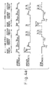
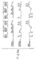
- the pulse Vs+Vw is applied to the odd-numbered scan electrodes Y 1 , Y 3 , ..., Y 2n-1 , while the potential of the pulse Vs+Vw being applied to the odd-numbered scan electrodes Y 1 , Y 3 , ..., Y 2n-1 is reduced to Vs.
- the even-numbered sustain electrodes X 2 , X 4 , ..., X 2i and the odd-numbered sustain electrodes X 1 , X 3 , ..., X 2i-1 are both at ground potential.
- the driving in the even field is essentially the same as that in the odd field, except that the display and non-display slits are interchanged.
- the positive polarity pulse Vs is applied to the odd-numbered sustain electrodes X 1 , X 3 , ..., X 2i-1 and the negative polarity pulse -Vw to the odd-numbered scan electrodes Y 1 , Y 3 , ..., Y 2n-1 .
- the even-numbered sustain electrodes X 2 , X 4 , ..., X 2i and scan electrodes Y 2 , Y 4 , ..., Y 2n which form the adjacent display slits, are both held at ground potential.
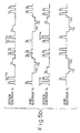
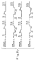
- the timing at which the second reset period is carried out is changed and the second reset period is initiated at a point halfway through the address period. More specifically, first the reset discharge in the first reset period is carried out between the odd-numbered scan electrodes and sustain electrodes, X 1 -Y 1 , X 3 -Y 3 , ..., X 2i-1 -Y 2n-1 , and then an address discharge is carried out in sequence between the same electrodes, X 1 -Y 1 , X 3 -Y 3 , ..., X 2i-1 -Y 2n-1 .
- Reset discharge is then carried out in the reset period of the first subfield in the even field.
- This reset discharge is carried out between the odd-numbered scan electrodes and even-numbered sustain electrodes, Y 1 -X 2 , Y 3 -X 4 , ..., Y 2n-1 -X 2i and also between the even-numbered scan electrodes and odd-numbered sustain electrodes, Y 2 -X 3 , Y 4 -X 5 , ..., Y 2n -X 2i-1 .
- the reset discharge is carried out in inner regions between the respective electrodes, thus tending to make it difficult to erase the wall charges remaining in the outer regions, that is, the inner regions between the electrodes where the discharge was carried out in the immediately preceding subfield.
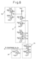
- the cathode of the diode D19 and the anode of the diode D20 are connected in common, and a power supply line of potential Vx is connected to the other terminals of the switch elements SW3 and SW4.
- Diodes D4 and D5 are connected in parallel with the switch elements SW3 and SW4, respectively.
- the cathode of the diode D19 and the anode of the diode D20, which are connected in common, are connected to the node between the switch elements SW1 and SW2 to provide an output of the X-common driver 3.
- a switch element SW5 and a switch element SW6 are connected in series between a power supply line of potential Vw and the ground line, and diodes D6 and D7 are connected in parallel with the switch elements SW5 and SW6, respectively.
- diodes D6 and D7 are connected in parallel with the switch elements SW5 and SW6, respectively.
- To the node between the switch elements SW5 and SW6 is connected one end of a capacitor C1 whose other end is connected to the node between the switch element SW1 and diode D1 in the X-common driver 3.
- the X negative write circuit B comprises a switch element SW9, connected between a power supply line of - Vyw and the node between the switch element SW7 and diode D21 in the X negative write circuit A, and a diode D10 connected in parallel with the switch element SW9.
- the switch element SW1 is turned on as needed, to produce the sustain discharge pulse Vs.
- each switch element is constructed from a D-FET which is a power FET capable of supplying large power.
- the D-FET (shown by a schematic representation for the X-side driver only) passes current only in one direction since essentially its source and drain are fixed, but at the same time, has a parasitic diode directed in the opposite direction. Accordingly, by using the D-FET, the diode connected in parallel with each element can be omitted.
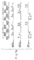
- FIG. 9 is a circuit diagram showing Y-side drivers embodying the present invention, wherein reference numeral 4 is a Y-scan driver, 5 is a Y-common driver, 53 is a Y positive write circuit, 54 is a Y negative write circuit A, and 55 is a Y negative write circuit B.
- a Y-common driver A connected to the odd-numbered electrodes Y o and a Y-common driver B connected to the even-numbered electrodes Y e are provided as the Y-common driver.
- the Y-scan drivers are connected to individual scan electrodes Y i , one driver driving each electrode independently.
- the Y-common driver is connected in common to the Y-scan drivers connected to the odd-numbered scan electrodes Y o or the Y-scan drivers connected to the even-numbered scan electrodes Y e , and drives the odd-numbered scan electrodes Y o or the even-numbered scan electrodes Y e .
- the other terminal of the switch element SW12 is connected to the ground line through the anode and cathode of a diode D15 and also to line FLG via a switch element SW13.
- the line FLG is connected to a power supply line of -Vy via a switch element SW14.
- the Y negative write circuit A includes a diode D18 whose cathode is connected to the power supply line of potential -Vw via a switch element SW19 and whose anode is connected to the line FVH of the Y-common driver.
- the Y negative write circuit B includes a switch element SW20 whose one end is connected to the power supply line of potential -Vyw and whose other end is connected to the line FVH of the Y-common driver.
- the switch element SW19 or SW20 is turned on as needed, causing current to flow via the diode D16 to the power supply line of -Vw or -Vyw to drive the odd-numbered electrodes Y o or the even-numbered electrodes Y e to the potential -Vw or -Vyw.
- the switch elements SW12 and SW13 are turned on to supply the potential Vs via the diodes D14 and D17.
- the switch element SW17 When supplying the potential Vs+Vw, the switch element SW17 is turned on so that the potential Vw is superimposed on the potential Vs being applied to the capacitor C2, and the resulting Vs+Vw is supplied via the diode D17 to the odd-numbered electrodes Y o or the even-numbered electrodes Y e .
- the switch element SW10 When lowering a positive potential scan electrode Y i to 0 V, the switch element SW10 is turn on and the other switch elements are turned off. This causes the current for bringing the scan electrode Y i to 0 V to flow from the scan electrode Y i and to pass through the diodes D16 and D12 and via the switch element SW10.
- the switch element SW13 When raising a negative potential scan electrode Y i to 0 V, the switch element SW13 is turned on and the other switch elements are turned off. This causes the current for driving the scan electrode Y i to 0 V to flow from the diode D15 and to pass through the switch element SW13 and diode D17.
- the potential Vs is applied to the scan electrode Y i through the diode D14, switch elements SW12 and SW13, and diode D17.
Landscapes
- Engineering & Computer Science (AREA)
- Physics & Mathematics (AREA)
- Power Engineering (AREA)
- Plasma & Fusion (AREA)
- Computer Hardware Design (AREA)
- General Physics & Mathematics (AREA)
- Theoretical Computer Science (AREA)
- Control Of Indicators Other Than Cathode Ray Tubes (AREA)
- Control Of Gas Discharge Display Tubes (AREA)
- Transforming Electric Information Into Light Information (AREA)
Applications Claiming Priority (3)
| Application Number | Priority Date | Filing Date | Title |
|---|---|---|---|
| JP01270097A JP3221341B2 (ja) | 1997-01-27 | 1997-01-27 | プラズマディスプレイパネルの駆動方法、プラズマディスプレイパネル及び表示装置 |
| JP12700/97 | 1997-01-27 | ||
| JP1270097 | 1997-01-27 |
Publications (2)
| Publication Number | Publication Date |
|---|---|
| EP0855691A1 true EP0855691A1 (fr) | 1998-07-29 |
| EP0855691B1 EP0855691B1 (fr) | 2005-05-04 |
Family
ID=11812679
Family Applications (1)
| Application Number | Title | Priority Date | Filing Date |
|---|---|---|---|
| EP97306454A Expired - Lifetime EP0855691B1 (fr) | 1997-01-27 | 1997-08-22 | Panneau d'affichage à plasma |
Country Status (6)
| Country | Link |
|---|---|
| US (1) | US6160529A (fr) |
| EP (1) | EP0855691B1 (fr) |
| JP (1) | JP3221341B2 (fr) |
| KR (1) | KR100271541B1 (fr) |
| DE (1) | DE69733190T2 (fr) |
| TW (1) | TW337575B (fr) |
Cited By (7)
| Publication number | Priority date | Publication date | Assignee | Title |
|---|---|---|---|---|
| WO2001004867A3 (fr) * | 1999-07-10 | 2001-05-10 | Koninkl Philips Electronics Nv | Procede de maintien progressif de l'attaque d'un ecran a plasma |
| FR2811127A1 (fr) * | 2000-06-30 | 2002-01-04 | Nec Corp | Dispositif d'affichage a plasma et procede de pilotage de celui-ci |
| EP1246156A1 (fr) * | 2001-03-26 | 2002-10-02 | Lg Electronics Inc. | Méthode de commande pour dispositif d'affichage au plasma avec inversion selective d'adressage |
| US6714175B1 (en) * | 1999-10-28 | 2004-03-30 | Fujitsu Limited | Plasma display panel and method for driving the panel |
| EP1528529A3 (fr) * | 1998-06-18 | 2005-08-17 | Fujitsu Limited | Méthode et dispositif de commande d'un panneau d'affichage à plasma |
| EP1528530A3 (fr) * | 1999-06-30 | 2006-08-02 | Hitachi, Ltd. | Appareil et procédé de commande pour un panneau d'affichage à plasma |
| EP1195738A3 (fr) * | 2000-10-04 | 2008-01-02 | Fujitsu Hitachi Plasma Display Limited | Méthode de commande d'un panneau d'affichage à plasma et appareil d'affichage |
Families Citing this family (42)
| Publication number | Priority date | Publication date | Assignee | Title |
|---|---|---|---|---|
| FR2758204B1 (fr) * | 1997-01-07 | 1999-04-09 | Thomson Tubes Electroniques | Procede de commande d'adressage d'un panneau a plasma de type alternatif |
| KR100347586B1 (ko) * | 1998-03-13 | 2002-11-29 | 현대 프라즈마 주식회사 | 교류형플라즈마디스플레이패널구동방법 |
| JP3640527B2 (ja) * | 1998-05-19 | 2005-04-20 | 富士通株式会社 | プラズマディスプレイ装置 |
| JP3420938B2 (ja) | 1998-05-27 | 2003-06-30 | 富士通株式会社 | プラズマディスプレイパネル駆動方法および駆動装置 |
| JP4210805B2 (ja) * | 1998-06-05 | 2009-01-21 | 株式会社日立プラズマパテントライセンシング | ガス放電デバイスの駆動方法 |
| KR100290830B1 (ko) * | 1998-07-04 | 2001-06-01 | 구자홍 | 플라즈마디스플레이패널구동방법및장치 |
| TW389883B (en) * | 1998-08-26 | 2000-05-11 | Acer Display Tech Inc | Method of driving the plasma display panel |
| KR100762065B1 (ko) | 1998-09-04 | 2007-10-01 | 마츠시타 덴끼 산교 가부시키가이샤 | 고화질과 고휘도를 표시할 수 있는 플라즈마 디스플레이패널 구동방법 및 화상 표시 장치 |
| JP2000112431A (ja) * | 1998-10-01 | 2000-04-21 | Fujitsu Ltd | ディスプレイ駆動方法及びその装置 |
| TW400530B (en) * | 1998-11-05 | 2000-08-01 | Acer Display Tech Inc | The method of decreasing the phenomena of dark area in the plasma monitor |
| JP3466098B2 (ja) | 1998-11-20 | 2003-11-10 | 富士通株式会社 | ガス放電パネルの駆動方法 |
| EP1022713A3 (fr) * | 1999-01-14 | 2000-12-06 | Nec Corporation | Méthode de commande d'un panneau d'affichage à plasma à courant alternatif |
| NO311317B1 (no) * | 1999-04-30 | 2001-11-12 | Thin Film Electronics Asa | Apparat omfattende elektroniske og/eller optoelektroniske kretser samt fremgangsmåte til å realisere og/eller integrerekretser av denne art i apparatet |
| JP2002006801A (ja) * | 2000-06-21 | 2002-01-11 | Fujitsu Hitachi Plasma Display Ltd | プラズマディスプレイパネルおよびその駆動方法 |
| JP2002014648A (ja) | 2000-06-28 | 2002-01-18 | Nec Corp | プラズマディスプレイパネルの駆動方法 |
| KR20020019670A (ko) * | 2000-09-06 | 2002-03-13 | 김순택 | 플라즈마 표시 패널의 구동 방법 |
| TW494372B (en) * | 2000-09-21 | 2002-07-11 | Au Optronics Corp | Driving method of plasma display panel and apparatus thereof |
| US6686897B2 (en) * | 2000-09-21 | 2004-02-03 | Au Optronics Corp. | Plasma display panel and method of driving the same |
| KR20030023719A (ko) * | 2001-05-29 | 2003-03-19 | 코닌클리케 필립스 일렉트로닉스 엔.브이. | 픽셀들을 디스플레이하기 위한 디스플레이 구동 유닛 및방법과 그러한 디스플레이 구동 유닛을 포함하는 이미지디스플레이 장치 |
| JP5063841B2 (ja) * | 2001-06-27 | 2012-10-31 | パナソニック株式会社 | プラズマディスプレイパネルの駆動方法 |
| KR100607511B1 (ko) * | 2001-08-17 | 2006-08-02 | 엘지전자 주식회사 | 플라즈마 디스플레이 패널의 구동 방법 |
| KR100458569B1 (ko) * | 2002-02-15 | 2004-12-03 | 삼성에스디아이 주식회사 | 플라즈마 디스플레이 패널의 구동방법 |
| KR20030079340A (ko) * | 2002-04-03 | 2003-10-10 | 오리온전기 주식회사 | 교류형 플라즈마 디스플레이 패널 구동 회로 및 그 구동방법 |
| KR100480152B1 (ko) * | 2002-05-17 | 2005-04-06 | 엘지전자 주식회사 | 플라즈마 디스플레이 패널의 구동방법 |
| EP1471491A3 (fr) * | 2003-04-22 | 2005-03-23 | Samsung SDI Co., Ltd. | Panneau d'affichage à plasma et son procédé de commande |
| KR100508921B1 (ko) * | 2003-04-29 | 2005-08-17 | 삼성에스디아이 주식회사 | 플라즈마 디스플레이 패널 및 그 구동 방법 |
| JP2005031479A (ja) * | 2003-07-08 | 2005-02-03 | Nec Plasma Display Corp | プラズマディスプレイ装置及びその駆動方法 |
| KR100515341B1 (ko) * | 2003-09-02 | 2005-09-15 | 삼성에스디아이 주식회사 | 플라즈마 디스플레이 패널의 구동 장치 |
| KR100551124B1 (ko) * | 2003-12-31 | 2006-02-13 | 엘지전자 주식회사 | 플라즈마 디스플레이 패널의 구동 방법 |
| KR100726634B1 (ko) * | 2004-04-27 | 2007-06-12 | 엘지전자 주식회사 | 플라즈마 표시 패널의 구동 방법 |
| KR100570970B1 (ko) * | 2004-05-06 | 2006-04-14 | 엘지전자 주식회사 | 플라즈마 디스플레이 패널의 구동방법 |
| JP4577681B2 (ja) * | 2004-07-30 | 2010-11-10 | 株式会社日立プラズマパテントライセンシング | プラズマディスプレイパネルの駆動方法 |
| JP4951907B2 (ja) * | 2005-09-16 | 2012-06-13 | 富士電機株式会社 | 半導体回路、インバータ回路および半導体装置 |
| JPWO2007088601A1 (ja) * | 2006-02-01 | 2009-06-25 | 日立プラズマディスプレイ株式会社 | プラズマディスプレイパネルの駆動方法およびプラズマディスプレイ装置 |
| JP4828994B2 (ja) * | 2006-04-13 | 2011-11-30 | パナソニック株式会社 | プラズマディスプレイパネルの駆動方法 |
| KR100793061B1 (ko) * | 2006-09-12 | 2008-01-10 | 엘지전자 주식회사 | 플라즈마 디스플레이 장치 및 그의 구동 방법 |
| US20080278415A1 (en) * | 2007-05-09 | 2008-11-13 | Pioneer Corporation | Method for driving plasma display panel |
| KR20090044780A (ko) * | 2007-11-01 | 2009-05-07 | 엘지전자 주식회사 | 플라즈마 디스플레이 장치 |
| KR100913586B1 (ko) * | 2007-11-01 | 2009-08-26 | 엘지전자 주식회사 | 플라즈마 디스플레이 장치 |
| KR20090044782A (ko) * | 2007-11-01 | 2009-05-07 | 엘지전자 주식회사 | 플라즈마 디스플레이 장치 |
| KR20110010127A (ko) * | 2008-06-26 | 2011-01-31 | 파나소닉 주식회사 | 플라즈마 디스플레이 패널의 구동 회로 및 플라즈마 디스플레이 장치 |
| KR20230092043A (ko) | 2021-12-16 | 2023-06-26 | 삼성디스플레이 주식회사 | 레이저 가공 장치 |
Citations (5)
| Publication number | Priority date | Publication date | Assignee | Title |
|---|---|---|---|---|
| JPH02220330A (ja) * | 1989-02-20 | 1990-09-03 | Fujitsu Ltd | ガス放電パネルとその駆動方法 |
| US5029257A (en) * | 1989-03-31 | 1991-07-02 | Samsung Electron Device Co., Ltd. | Method for separating scan line drive in plasma display panel and circuit arrangement thereof |
| JPH052993A (ja) * | 1991-06-26 | 1993-01-08 | Fujitsu Ltd | 面放電型プラズマデイスプレイパネル及びその駆動方法 |
| US5436634A (en) * | 1992-07-24 | 1995-07-25 | Fujitsu Limited | Plasma display panel device and method of driving the same |
| EP0762373A2 (fr) * | 1995-08-03 | 1997-03-12 | Fujitsu Limited | Panneau d'affichage à plasma, méthode de commande de mise en oeuvre d'un balayage entrelacé, et appareil d'affichage à plasma |
Family Cites Families (5)
| Publication number | Priority date | Publication date | Assignee | Title |
|---|---|---|---|---|
| US4772884A (en) * | 1985-10-15 | 1988-09-20 | University Patents, Inc. | Independent sustain and address plasma display panel |
| JP2772753B2 (ja) * | 1993-12-10 | 1998-07-09 | 富士通株式会社 | プラズマディスプレイパネル並びにその駆動方法及び駆動回路 |
| JP3644712B2 (ja) * | 1994-02-01 | 2005-05-11 | 富士通株式会社 | 平面表示装置 |
| US5656893A (en) * | 1994-04-28 | 1997-08-12 | Matsushita Electric Industrial Co., Ltd. | Gas discharge display apparatus |
| JP3704813B2 (ja) * | 1996-06-18 | 2005-10-12 | 三菱電機株式会社 | プラズマディスプレイパネルの駆動方法及びプラズマディスプレイ |
-
1997
- 1997-01-27 JP JP01270097A patent/JP3221341B2/ja not_active Expired - Fee Related
- 1997-08-22 TW TW086112087A patent/TW337575B/zh not_active IP Right Cessation
- 1997-08-22 EP EP97306454A patent/EP0855691B1/fr not_active Expired - Lifetime
- 1997-08-22 DE DE69733190T patent/DE69733190T2/de not_active Expired - Lifetime
- 1997-08-25 US US08/917,332 patent/US6160529A/en not_active Expired - Fee Related
- 1997-09-05 KR KR1019970045913A patent/KR100271541B1/ko not_active Expired - Fee Related
Patent Citations (5)
| Publication number | Priority date | Publication date | Assignee | Title |
|---|---|---|---|---|
| JPH02220330A (ja) * | 1989-02-20 | 1990-09-03 | Fujitsu Ltd | ガス放電パネルとその駆動方法 |
| US5029257A (en) * | 1989-03-31 | 1991-07-02 | Samsung Electron Device Co., Ltd. | Method for separating scan line drive in plasma display panel and circuit arrangement thereof |
| JPH052993A (ja) * | 1991-06-26 | 1993-01-08 | Fujitsu Ltd | 面放電型プラズマデイスプレイパネル及びその駆動方法 |
| US5436634A (en) * | 1992-07-24 | 1995-07-25 | Fujitsu Limited | Plasma display panel device and method of driving the same |
| EP0762373A2 (fr) * | 1995-08-03 | 1997-03-12 | Fujitsu Limited | Panneau d'affichage à plasma, méthode de commande de mise en oeuvre d'un balayage entrelacé, et appareil d'affichage à plasma |
Non-Patent Citations (2)
| Title |
|---|
| PATENT ABSTRACTS OF JAPAN vol. 14, no. 520 (E - 1022) 14 November 1990 (1990-11-14) * |
| PATENT ABSTRACTS OF JAPAN vol. 17, no. 257 (E - 1368) 20 May 1993 (1993-05-20) * |
Cited By (21)
| Publication number | Priority date | Publication date | Assignee | Title |
|---|---|---|---|---|
| US7345667B2 (en) | 1998-06-18 | 2008-03-18 | Hitachi, Ltd. | Method for driving plasma display panel |
| US8791933B2 (en) | 1998-06-18 | 2014-07-29 | Hitachi Maxell, Ltd. | Method for driving plasma display panel |
| US8558761B2 (en) | 1998-06-18 | 2013-10-15 | Hitachi Consumer Electronics Co., Ltd. | Method for driving plasma display panel |
| US8344631B2 (en) | 1998-06-18 | 2013-01-01 | Hitachi Plasma Patent Licensing Co., Ltd. | Method for driving plasma display panel |
| US8022897B2 (en) | 1998-06-18 | 2011-09-20 | Hitachi Plasma Licensing Co., Ltd. | Method for driving plasma display panel |
| US8018168B2 (en) | 1998-06-18 | 2011-09-13 | Hitachi Plasma Patent Licensing Co., Ltd. | Method for driving plasma display panel |
| EP1528529A3 (fr) * | 1998-06-18 | 2005-08-17 | Fujitsu Limited | Méthode et dispositif de commande d'un panneau d'affichage à plasma |
| US7009585B2 (en) | 1998-06-18 | 2006-03-07 | Fujitsu Limited | Method for driving plasma display panel |
| US8018167B2 (en) | 1998-06-18 | 2011-09-13 | Hitachi Plasma Licensing Co., Ltd. | Method for driving plasma display panel |
| US7906914B2 (en) | 1998-06-18 | 2011-03-15 | Hitachi, Ltd. | Method for driving plasma display panel |
| US7825875B2 (en) | 1998-06-18 | 2010-11-02 | Hitachi Plasma Patent Licensing Co., Ltd. | Method for driving plasma display panel |
| EP1528530A3 (fr) * | 1999-06-30 | 2006-08-02 | Hitachi, Ltd. | Appareil et procédé de commande pour un panneau d'affichage à plasma |
| US6731255B1 (en) | 1999-07-10 | 2004-05-04 | Koninklijke Philips Electronics N.V. | Progressive sustain method of driving a plasma display panel |
| WO2001004867A3 (fr) * | 1999-07-10 | 2001-05-10 | Koninkl Philips Electronics Nv | Procede de maintien progressif de l'attaque d'un ecran a plasma |
| US6714175B1 (en) * | 1999-10-28 | 2004-03-30 | Fujitsu Limited | Plasma display panel and method for driving the panel |
| FR2826768A1 (fr) * | 2000-06-30 | 2003-01-03 | Nec Corp | Procede de pilotage de dispositif d'affichage a plasma |
| FR2811127A1 (fr) * | 2000-06-30 | 2002-01-04 | Nec Corp | Dispositif d'affichage a plasma et procede de pilotage de celui-ci |
| EP1195738A3 (fr) * | 2000-10-04 | 2008-01-02 | Fujitsu Hitachi Plasma Display Limited | Méthode de commande d'un panneau d'affichage à plasma et appareil d'affichage |
| CN100353398C (zh) * | 2001-03-26 | 2007-12-05 | Lg电子株式会社 | 使用选择性转换寻址方法驱动等离子显示板的方法 |
| US7091935B2 (en) | 2001-03-26 | 2006-08-15 | Lg Electronics Inc. | Method of driving plasma display panel using selective inversion address method |
| EP1246156A1 (fr) * | 2001-03-26 | 2002-10-02 | Lg Electronics Inc. | Méthode de commande pour dispositif d'affichage au plasma avec inversion selective d'adressage |
Also Published As
| Publication number | Publication date |
|---|---|
| JPH10207417A (ja) | 1998-08-07 |
| KR19980069930A (ko) | 1998-10-26 |
| DE69733190T2 (de) | 2005-11-10 |
| TW337575B (en) | 1998-08-01 |
| JP3221341B2 (ja) | 2001-10-22 |
| EP0855691B1 (fr) | 2005-05-04 |
| DE69733190D1 (de) | 2005-06-09 |
| KR100271541B1 (ko) | 2000-11-15 |
| US6160529A (en) | 2000-12-12 |
Similar Documents
| Publication | Publication Date | Title |
|---|---|---|
| EP0855691B1 (fr) | Panneau d'affichage à plasma | |
| US6288693B1 (en) | Plasma display panel driving method | |
| JP5146410B2 (ja) | プラズマディスプレイ装置の駆動方法 | |
| US6573878B1 (en) | Method of driving AC-discharge plasma display panel | |
| JP3259766B2 (ja) | プラズマディスプレイパネルの駆動方法 | |
| KR100341218B1 (ko) | 플라즈마 디스플레이의 구동 방법 및 플라즈마 디스플레이 구동 | |
| US7427969B2 (en) | Plasma display apparatus | |
| US20030102812A1 (en) | Suppression of vertical crosstalk in a plasma display panel | |
| JP3231569B2 (ja) | プラズマディスプレイパネルの駆動方法および駆動装置 | |
| JP3485874B2 (ja) | Pdpの駆動方法および表示装置 | |
| KR100607894B1 (ko) | 플라즈마 표시 장치 및 상기 플라즈마 표시 장치에이용되는 구동 방법 | |
| JP3630640B2 (ja) | プラズマディスプレイパネルおよびその駆動方法 | |
| US20060145956A1 (en) | Plasma display panel and driving method thereof | |
| US7006060B2 (en) | Plasma display panel and method of driving the same capable of providing high definition and high aperture ratio | |
| US7417602B2 (en) | Plasma display panel and driving method thereof | |
| US20050212723A1 (en) | Driving method of plasma display panel and plasma display device | |
| JP4332585B2 (ja) | プラズマディスプレイパネルの駆動方法 | |
| US20020043940A1 (en) | Method of driving plasma display panel and a plasma display panel using the method | |
| JP4438131B2 (ja) | 表示パネルの駆動方法と放電式表示装置 | |
| KR100648879B1 (ko) | 플라즈마 디스플레이 장치 및 플라즈마 디스플레이 장치에사용되는 구동방법 | |
| KR20010046350A (ko) | 플라즈마 디스플레이 패널의 구동방법 | |
| JP4223541B2 (ja) | プラズマディスプレイパネルの駆動方法 | |
| JP4387206B2 (ja) | プラズマディスプレイパネル | |
| JP3402272B2 (ja) | プラズマディスプレイパネル駆動方法 | |
| US20050264475A1 (en) | Plasma display device and driving method thereof |
Legal Events
| Date | Code | Title | Description |
|---|---|---|---|
| PUAI | Public reference made under article 153(3) epc to a published international application that has entered the european phase |
Free format text: ORIGINAL CODE: 0009012 |
|
| AK | Designated contracting states |
Kind code of ref document: A1 Designated state(s): DE FR GB |
|
| AX | Request for extension of the european patent |
Free format text: AL;LT;LV;RO;SI |
|
| 17P | Request for examination filed |
Effective date: 19980622 |
|
| AKX | Designation fees paid |
Free format text: DE FR GB |
|
| RBV | Designated contracting states (corrected) |
Designated state(s): DE FR GB |
|
| GRAP | Despatch of communication of intention to grant a patent |
Free format text: ORIGINAL CODE: EPIDOSNIGR1 |
|
| GRAS | Grant fee paid |
Free format text: ORIGINAL CODE: EPIDOSNIGR3 |
|
| GRAA | (expected) grant |
Free format text: ORIGINAL CODE: 0009210 |
|
| AK | Designated contracting states |
Kind code of ref document: B1 Designated state(s): DE FR GB |
|
| REG | Reference to a national code |
Ref country code: GB Ref legal event code: FG4D |
|
| REF | Corresponds to: |
Ref document number: 69733190 Country of ref document: DE Date of ref document: 20050609 Kind code of ref document: P |
|
| REG | Reference to a national code |
Ref country code: GB Ref legal event code: 732E |
|
| ET | Fr: translation filed | ||
| PLBE | No opposition filed within time limit |
Free format text: ORIGINAL CODE: 0009261 |
|
| STAA | Information on the status of an ep patent application or granted ep patent |
Free format text: STATUS: NO OPPOSITION FILED WITHIN TIME LIMIT |
|
| REG | Reference to a national code |
Ref country code: FR Ref legal event code: TP |
|
| 26N | No opposition filed |
Effective date: 20060207 |
|
| REG | Reference to a national code |
Ref country code: GB Ref legal event code: 732E |
|
| REG | Reference to a national code |
Ref country code: FR Ref legal event code: TP |
|
| PGFP | Annual fee paid to national office [announced via postgrant information from national office to epo] |
Ref country code: FR Payment date: 20090814 Year of fee payment: 13 |
|
| PGFP | Annual fee paid to national office [announced via postgrant information from national office to epo] |
Ref country code: GB Payment date: 20090818 Year of fee payment: 13 Ref country code: DE Payment date: 20090821 Year of fee payment: 13 |
|
| GBPC | Gb: european patent ceased through non-payment of renewal fee |
Effective date: 20100822 |
|
| REG | Reference to a national code |
Ref country code: FR Ref legal event code: ST Effective date: 20110502 |
|
| REG | Reference to a national code |
Ref country code: DE Ref legal event code: R119 Ref document number: 69733190 Country of ref document: DE Effective date: 20110301 |
|
| PG25 | Lapsed in a contracting state [announced via postgrant information from national office to epo] |
Ref country code: FR Free format text: LAPSE BECAUSE OF NON-PAYMENT OF DUE FEES Effective date: 20100831 Ref country code: DE Free format text: LAPSE BECAUSE OF NON-PAYMENT OF DUE FEES Effective date: 20110301 |
|
| PG25 | Lapsed in a contracting state [announced via postgrant information from national office to epo] |
Ref country code: GB Free format text: LAPSE BECAUSE OF NON-PAYMENT OF DUE FEES Effective date: 20100822 |