EP0855843A2 - Channel selection control in a selective call receiver - Google Patents
Channel selection control in a selective call receiver Download PDFInfo
- Publication number
- EP0855843A2 EP0855843A2 EP98101334A EP98101334A EP0855843A2 EP 0855843 A2 EP0855843 A2 EP 0855843A2 EP 98101334 A EP98101334 A EP 98101334A EP 98101334 A EP98101334 A EP 98101334A EP 0855843 A2 EP0855843 A2 EP 0855843A2
- Authority
- EP
- European Patent Office
- Prior art keywords
- signal
- radio
- predetermined
- received signal
- channel
- Prior art date
- Legal status (The legal status is an assumption and is not a legal conclusion. Google has not performed a legal analysis and makes no representation as to the accuracy of the status listed.)
- Granted
Links
Images


Classifications
-
- H—ELECTRICITY
- H03—ELECTRONIC CIRCUITRY
- H03J—TUNING RESONANT CIRCUITS; SELECTING RESONANT CIRCUITS
- H03J1/00—Details of adjusting, driving, indicating, or mechanical control arrangements for resonant circuits in general
- H03J1/0008—Details of adjusting, driving, indicating, or mechanical control arrangements for resonant circuits in general using a central processing unit, e.g. a microprocessor
-
- H—ELECTRICITY
- H04—ELECTRIC COMMUNICATION TECHNIQUE
- H04W—WIRELESS COMMUNICATION NETWORKS
- H04W88/00—Devices specially adapted for wireless communication networks, e.g. terminals, base stations or access point devices
- H04W88/02—Terminal devices
- H04W88/022—Selective call receivers
-
- H—ELECTRICITY
- H04—ELECTRIC COMMUNICATION TECHNIQUE
- H04B—TRANSMISSION
- H04B1/00—Details of transmission systems, not covered by a single one of groups H04B3/00 - H04B13/00; Details of transmission systems not characterised by the medium used for transmission
- H04B1/06—Receivers
- H04B1/16—Circuits
- H04B1/18—Input circuits, e.g. for coupling to an antenna or a transmission line
-
- H—ELECTRICITY
- H04—ELECTRIC COMMUNICATION TECHNIQUE
- H04W—WIRELESS COMMUNICATION NETWORKS
- H04W48/00—Access restriction; Network selection; Access point selection
- H04W48/16—Discovering, processing access restriction or access information
Definitions
- the present invention relates to a radio selective call receiver and, more specifically, to a channel selection control method in the radio selective call receiver.
- a cordless telephone having an available-channel determination function has been disclosed in Japanese Patent Unexamined Publication No. 1-202939.
- the cordless telephone is provided with an attenuator at the previous stage of a high-frequency amplifier. Since the attenuator attenuates the level of radio received signal, the effect of strong interference waves can be reduced.
- the receiving sensitivity is set to a maximum level to increase the probability of detection of a calling area. Therefore, in cases where a plurality of calling areas are overlapped, an optimal calling channel is not always detected. There is a possibility that a receiving channel with lower signal level is selected.
- An object of the present invention is to provide a channel selection control method which can increase the reliability of receiving channel.
- Another object of the present invention is to provide a radio selective call receiver and a channel selection control method which are capable of establishing synchronization with reliability in the case of two or more radio selective calling signals being overlapped.
- the sensitivity of a radio receiver is set to a first sensitivity level which is lower than a second sensitivity level of the radio receiver.
- the predetermined channels are searched for a receiving channel while receiving a radio signal before searching in the second sensitivity level.
- the radio signal is received and a receiving channel is searched for in the state that the sensitivity of the radio receiver is lowered, a receiving channel with higher signal level can be selected and the synchronization can be established.
- a radio selective call receiver having a channel scan function of scanning a plurality of predetermined channels in a predetermined order to search for a receiving channel
- the first radio received signal is demodulated to a first baseband received signal and it is determining whether a predetermined signal format is detected from the first baseband received signal.
- the predetermined channels are scanned according to the predetermined order in the attenuation state that the radio received signal is attenuated.
- the radio received signal which is not attenuated is demodulated to a second baseband received signal, and it is determined whether the predetermined signal format is detected from the second baseband received signal.
- the predetermined channels are scanned according to the predetermined order a first predetermined number of times in the normal state that the radio received signal is not attenuated.
- a receiving channel with higher signal level can be selected with reliability.
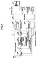
- a selective call receiver is mainly comprised of a radio system 10, a controller 11, and a man-machine interface 12.
- the radio system 10 is connected to an antenna and receives radio waves through the antenna.
- the controller 11 inputs a baseband received signal from the radio system 10 and controls the radio system as will be described.
- the man-machine interface 12 includes a display such as liquid-crystal display, a keypad, and an informer such as a beeper, an LED or a vibrator.
- the radio system 10 includes a variable attenuator 100 which attenuates radio waves received from the antenna under the control of the controller 11.
- the radio waves output from the attenuator 100 are amplified by a variable-gain high-frequency amplifier 101 and then are output to a frequency converter 102.
- the frequency converter 102 is comprised of a radio-frequency (RF) filter, a mixer and an intermediate-frequency (IF) filter, which are not shown in this figure.
- a PLL (phase-locked loop) synthesizer 103 generates a local frequency signal having a frequency controlled by a channel selection signal S CH .
- the radio waves are converted to an IF signal of a designated frequency by the mixer mixing the radio waves with the local frequency signal generated by the PLL synthesizer 103.
- the IF signal passing through the IF filter is output to a demodulator 104.
- the demodulator 104 demodulates the IF signal into a baseband signal which is output to the controller 11.
- a decoder 105 and a sync signal detector 106 receive the baseband received signal from the demodulator 104 of the radio system 10.
- the decoder 105 performs a decoding operation with error-correction of the received baseband signal and then outputs decoded and error-corrected data to a processor 107.
- the sync signal detector 106 detects a sync signal (SYNC) of each frame from the received baseband signal (see Fig. 5). Upon detecting the sync signal, the sync signal detector 106 outputs a sync interrupt signal to the processor 107.
- SYNC sync signal
- the controller 11 further includes a receiving controller 108 and a scan list memory 109. More specifically, the receiving controller 108 outputs an attenuation control signal S ATT to the variable attenuator 100. The receiving controller 108 further outputs a gain control signal S G and a channel selection signal S CH to the high-frequency amplifier 101 and the PLL synthesizer 103, respectively. Furthermore, the receiving controller 108 performs well-known intermittent receiving control of the radio system 10.
- the channel selection control is performed by the processor 107 while referring to the scan list memory 109 and the receiving controller 108 outputting the attenuation control signal S ATT , the gain control signal S G and the channel selection signal S CH .
- An ID-ROM (identification read-only memory) 110 and a ROM 111 are connected to the processor 107.
- the ID-ROM 110 stores a predetermined identification number and the ROM 111 stores programs including a channel selection control program and a message receiving program.
- the processor 107 can implement necessary functions of the selective call receiver. For example, after synchronization has been established according to the channel selection control program, the processor 107 runs the message receiving program to compare a calling number included in a received selective calling signal with the predetermined identification number stored in the ID-ROM 110. When they are coincident to each other, the processor 107 controls the man-machine interface 12 to inform the user of the incoming call and to display a received message on screen.
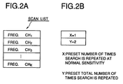
- the scan list memory 109 stores the sequence of designation of frequency channels CH 1 -CH K .
- the receiving channel is designated according to the sequence from the frequency channel CH 1 to the last frequency channel CH K .
- the designation position returns to the top frequency channel CH 1 .
- the scan list memory 109 further stores preset data consisting of a preset maximum number X of times that channel search repeats at normal sensitivity and a preset maximum total number Y of times that channel search repeats.
- the preset data X and Y are used in the channel selection control procedure.
- initialization is performed such that a first variable N indicating the number of times that channel search has repeated at normal sensitivity level and a second variable M indicating the total number of times that channel search has repeated are both reset to zero (step S201).
- the receiving controller 108 outputs the attenuation control signal S ATT to the attenuator 100 so that received radio signals are attenuated by a predetermined amount (step S202).
- the reception sensitivity is set to a level lower than the normal level.
- the receiving operation is started according to the scan list stored in the scan list memory 109.
- the processor 107 gets access to the head location of the scan list memory 109 and designates the frequency channel CH 1 as a receiving channel by setting the PLL synthesizer 103 to an oscillation state corresponding to the frequency channel CH 1 (step S203).
- the sync signal or the like is detected from the received selective calling signal (step S204).
- the sync establishment procedure is performed at the frequency channel CH 1 (step S205).
- step S206 When the sync signal or the like has not been detected (NO in step S204), it is checked whether the present channel designation position is at the end of the scan list (step S206). If it is not at the end of the scan list (NO in step S206), the next channel is designated (step S207) and then the above scan steps S203-S206 are repeated until the sync signal is detected or the channel designation position reaches the end of scan list. In other words, the channel search in the low sensitivity state is repeated according to the sequence of frequency channels stored in the scan list memory 109 until the sync signal is detected or the channel designation position reaches the end of scan list.
- the receiving operation is performed according to the scan list as described above (steps S203-S206).
- the sync signal has never been detected over the frequency channels in the normal sensitivity state (YES in step S206)
- it is checked whether the first variable N (here, N 1) is smaller than the preset maximum number X (step S208).
- the receiving controller 108 outputs the attenuation control signal S ATT to the attenuator 100 so that received radio signals are attenuated by a predetermined amount (step S202) and the above steps S203-S212 are repeated until the second variable M is equal to or greater than Y. If the second variable M is equal to or greater than Y (NO in step S211), it is determined that there is no available channel (step S213).
- the sequence of 4 frequency channels CH 1 -CH 4 is predetermined in the order presented.
- the receiving operation is performed in the low receiving sensitivity for the first cycle from the frequency channel CH 1 to CH 4 .
- the time required for detection of the sync signal for each frequency channel may be set to a predetermined time period t.
- the receiving sensitivity is set to the normal level and then the receiving operation is repeated.
- the channel scan is performed in the low sensitivity state and, if no channel is found, then the channel scan is further performed in the normal sensitivity state. Since the channel scan is first performed in the low sensitivity state, it is possible to select a radio channel having a stronger signal level from a plurality of available radio channels. Therefore, in the case where a plurality of calling areas are overlapped, the selective call receiver according to the present invention increases the possibility of selecting an optimal radio channel. Further, it is possible to avoid causing a channel not to be detected due to instantaneous sensitivity reduction such as fading.
- the attenuation of received radio signals may be achieved not only by the attenuator 100 but also by both the attenuator 100 and the high-frequency amplifier 101. More specifically, by controlling an attenuation amount of the attenuator 100 and a gain of the amplifier 101, the signal level of received radio signals can be set to three or more levels. Therefore, the channel selection may be sequentially performed for the signal levels of received radio signals in the ascending order.
Landscapes
- Engineering & Computer Science (AREA)
- Computer Networks & Wireless Communication (AREA)
- Signal Processing (AREA)
- Computer Hardware Design (AREA)
- Microelectronics & Electronic Packaging (AREA)
- Computer Security & Cryptography (AREA)
- Mobile Radio Communication Systems (AREA)
- Circuits Of Receivers In General (AREA)
- Channel Selection Circuits, Automatic Tuning Circuits (AREA)
Abstract
Description
Claims (13)
- A method for searching a plurality of predetermined channels (CH1-CHK) for a receiving channel in a radio receiver (10), characterized by the steps of:a) (S202) setting sensitivity of the radio receiver to a first sensitivity level which is lower than a second sensitivity level of the radio receiver; andb) (S203-208) searching the predetermined channels for the receiving channel while receiving a radio signal in the first sensitivity level before searching in the second sensitivity level.
- The method according to claim 1, further comprising the steps of:c) (S210) setting sensitivity of the radio receiver to the second sensitivity level when the receiving channel has not been found in the step b); andd) (S203-S208) searching the predetermined channels for the receiving channel while receiving a radio signal in the second sensitivity level.
- The method according to claim 2, whereinthe step d) is repeated a first predetermined number of times when the receiving channel has not been found (S208); andthe steps a) to d) are repeated a second predetermined number of times when the receiving channel has not been found (S211).
- The method according to claim 1, wherein the step b) comprises the steps of:b-1) selecting a first channel from the predetermined channels;b-2) receiving the radio signal at the first channel;b-3) determining whether a predetermined signal format is detected from the radio signal within a predetermined time period;b-4) designating the first channel as the receiving channel when the predetermined signal format is detected from the radio signal within the predetermined time period; andb-5) repeating the steps b-1) to b-4) while sequentially selecting a channel from the predetermined channels in a predetermined order until the predetermined channels have been selected.
- A control method for a radio selective call receiver having a channel scan function of scanning a plurality of predetermined channels in a predetermined order to search for a receiving channel, characterized by the steps of:a) (S202) attenuating a radio received signal by a predetermined amount to produce a first radio received signal;b) demodulating the first radio received signal to a first baseband received signal;c) determining whether a predetermined signal format is detected from the first baseband received signal;d) (S203-S207) scanning the predetermined channels according to the predetermined order while performing the steps a) to c) when the predetermined signal format is not detected from the first baseband received signal.
- The control method according to claim 5, further comprising the steps of:e) demodulating the radio received signal to a second baseband received signal when the predetermined signal format is not detected from the first baseband received signal in the step d);f) determining whether the predetermined signal format is detected from the second baseband received signal;g) (S209, S210, S203-S208) scanning the predetermined channels according to the predetermined order while performing the steps e) and f) a first predetermined number of times when the predetermined signal format is not detected from the second baseband received signal.
- The control method according to claim 6, further comprising the steps of:h) repeating the steps a) to g) a second predetermined number of times when the predetermined signal format is not detected from the second baseband received signal in the step g).
- A radio selective call receiver comprising:a signal level adjuster (100) for adjusting a signal level of a radio received signal to produce an adjusted radio received signal;a channel selector (102, 103) for selecting a receiving channel from a plurality of predetermined channels in a predetermined order;a demodulator (104) for demodulating the adjusted radio received signal obtained at a selected receiving channel to produce a first baseband received signal; anda detector (106) for detecting a predetermined signal format from the first baseband received signal,
characterized bya controller (107-109) for controlling the signal level adjuster and the channel selector such that the signal level adjuster decreases the signal level of the radio received signal to produce the adjusted radio received signal and, when the predetermined signal format is not detected from the first baseband received signal, the channel selector scans the predetermined channels according to the predetermined order in a decreased signal level state. - The radio selective call receiver according to claim 8, wherein the signal level adjuster comprises:a variable attenuator (100) for attenuating the radio received signal to produce a first radio received signal; andan variable-gain amplifier (101) for amplifying the first radio received signal to produce the adjusted radio received signal.
- The radio selective call receiver according to claim 8, wherein the signal level adjuster comprises:a variable attenuator (100) for attenuating the radio received signal to produce the adjusted radio received signal.
- The radio selective call receiver according to claim 7, wherein the controller controls the signal level adjuster and the channel selector such that the signal level adjuster sets the signal level of the radio received signal to a normal level when the predetermined signal format has not been detected from the first baseband received signal in the decreased signal level state and the channel selector scans the predetermined channels a first predetermined number of times according to the predetermined order in a normal level state.
- The radio selective call receiver according to claim 11, wherein the controller controls the signal level adjuster and the channel selector such that the predetermined channels are scanned a second predetermined number of times in the decreased signal level state and the normal level state.
- A method for searching a plurality of predetermined channels for a receiving channel in a radio receiver, characterized by the steps of:searching the predetermined channels for the receiving channel while receiving a radio signal in an attenuation state that a receiving sensitivity of the radio receiver is reduced; andsearching the predetermined channels for the receiving channel while receiving a radio signal in a normal state that the receiving sensitivity of the radio receiver is not reduced when the receiving channel has not been found in the attenuation state.
Applications Claiming Priority (3)
| Application Number | Priority Date | Filing Date | Title |
|---|---|---|---|
| JP14230/97 | 1997-01-28 | ||
| JP1423097 | 1997-01-28 | ||
| JP9014230A JP3037175B2 (en) | 1997-01-28 | 1997-01-28 | Radio selective call receiver |
Publications (3)
| Publication Number | Publication Date |
|---|---|
| EP0855843A2 true EP0855843A2 (en) | 1998-07-29 |
| EP0855843A3 EP0855843A3 (en) | 1998-12-16 |
| EP0855843B1 EP0855843B1 (en) | 2001-12-05 |
Family
ID=11855280
Family Applications (1)
| Application Number | Title | Priority Date | Filing Date |
|---|---|---|---|
| EP98101334A Expired - Lifetime EP0855843B1 (en) | 1997-01-28 | 1998-01-27 | Channel selection control in a selective call receiver |
Country Status (7)
| Country | Link |
|---|---|
| US (1) | US6263196B1 (en) |
| EP (1) | EP0855843B1 (en) |
| JP (1) | JP3037175B2 (en) |
| KR (1) | KR19980070917A (en) |
| CN (1) | CN1201340A (en) |
| DE (1) | DE69802718T2 (en) |
| TW (1) | TW462195B (en) |
Cited By (1)
| Publication number | Priority date | Publication date | Assignee | Title |
|---|---|---|---|---|
| GB2492960A (en) * | 2011-07-15 | 2013-01-23 | Toumaz Uk Ltd | Incrementally increasing the sensitivity of a sensor node when scanning for network attachment |
Families Citing this family (7)
| Publication number | Priority date | Publication date | Assignee | Title |
|---|---|---|---|---|
| KR20000009183A (en) * | 1998-07-22 | 2000-02-15 | 이가형 | Pager channel selecting method in overlapped area and the pager |
| US6904101B1 (en) * | 2000-02-17 | 2005-06-07 | Lear Corporation | Tuneless narrow-band super-regenerative receiver |
| JP3600568B2 (en) * | 2001-09-28 | 2004-12-15 | 株式会社東芝 | Wireless LAN access point |
| DE60319001T2 (en) * | 2002-06-07 | 2009-01-29 | Nxp B.V. | METHOD AND CIRCUIT FOR AUTOMATIC TUNING IN A FM BROADBOX RECEIVER |
| KR101317880B1 (en) * | 2006-07-14 | 2013-10-16 | 삼성전자주식회사 | Method for determining channels to be used a wireless network, method for wireless communication, and apparatus for the same |
| US20090237218A1 (en) * | 2007-06-08 | 2009-09-24 | Nam Yun Kim | Wireless communication device |
| US8036696B2 (en) * | 2008-09-18 | 2011-10-11 | At&T Intellectual Property I, L.P. | Time-multiplexed, two tier wireless device and method therefor |
Family Cites Families (12)
| Publication number | Priority date | Publication date | Assignee | Title |
|---|---|---|---|---|
| US4166927A (en) * | 1978-07-21 | 1979-09-04 | British Columbia Telephone Company | Apparatus and method for frequency channel selection in a radiotelephone system |
| JPS59153178A (en) | 1983-02-21 | 1984-09-01 | Advantest Corp | Signal detector |
| JPH01202939A (en) | 1988-02-08 | 1989-08-15 | Toshiba Corp | Idle channel deciding system for cordless telephone system |
| JPH06222732A (en) | 1991-02-21 | 1994-08-12 | Nec Corp | Light emitting diode device |
| JP2725480B2 (en) * | 1991-06-25 | 1998-03-11 | 日本電気株式会社 | Radio selective call receiver |
| JP2730347B2 (en) * | 1991-10-09 | 1998-03-25 | 松下電器産業株式会社 | Automatic receiver gain control method |
| JP2503946B2 (en) * | 1993-04-28 | 1996-06-05 | 日本電気株式会社 | Selective call receiver |
| JP2727948B2 (en) * | 1993-12-28 | 1998-03-18 | 日本電気株式会社 | Radio selective call receiver |
| JP3319131B2 (en) | 1994-03-28 | 2002-08-26 | 株式会社明電舎 | Chassis dynamometer for radio wave measurement |
| JP2868998B2 (en) | 1994-03-14 | 1999-03-10 | 株式会社デンソー | Scroll compressor |
| JP2689932B2 (en) * | 1994-12-30 | 1997-12-10 | 日本電気株式会社 | Radio selective call receiver |
| JPH08268173A (en) | 1995-03-31 | 1996-10-15 | Seiko Kogyo Kk | Roof carrier |
-
1997
- 1997-01-28 JP JP9014230A patent/JP3037175B2/en not_active Expired - Fee Related
-
1998
- 1998-01-26 TW TW087101060A patent/TW462195B/en not_active IP Right Cessation
- 1998-01-27 DE DE69802718T patent/DE69802718T2/en not_active Expired - Fee Related
- 1998-01-27 CN CN98105658A patent/CN1201340A/en active Pending
- 1998-01-27 US US09/013,903 patent/US6263196B1/en not_active Expired - Fee Related
- 1998-01-27 EP EP98101334A patent/EP0855843B1/en not_active Expired - Lifetime
- 1998-01-30 KR KR1019980002499A patent/KR19980070917A/en not_active Ceased
Cited By (3)
| Publication number | Priority date | Publication date | Assignee | Title |
|---|---|---|---|---|
| GB2492960A (en) * | 2011-07-15 | 2013-01-23 | Toumaz Uk Ltd | Incrementally increasing the sensitivity of a sensor node when scanning for network attachment |
| WO2013011263A1 (en) * | 2011-07-15 | 2013-01-24 | Toumaz Uk Limited | Method for power saving in bio sensor when attaching to base station, system and bio sensor |
| GB2492960B (en) * | 2011-07-15 | 2015-12-30 | Toumaz Uk Ltd | A wireless communication method and system |
Also Published As
| Publication number | Publication date |
|---|---|
| KR19980070917A (en) | 1998-10-26 |
| DE69802718D1 (en) | 2002-01-17 |
| US6263196B1 (en) | 2001-07-17 |
| CN1201340A (en) | 1998-12-09 |
| EP0855843B1 (en) | 2001-12-05 |
| EP0855843A3 (en) | 1998-12-16 |
| JP3037175B2 (en) | 2000-04-24 |
| JPH10210522A (en) | 1998-08-07 |
| TW462195B (en) | 2001-11-01 |
| DE69802718T2 (en) | 2002-09-26 |
Similar Documents
| Publication | Publication Date | Title |
|---|---|---|
| EP0886388B1 (en) | Transmitter, receiver and power control in a data transmission system | |
| US5010584A (en) | Mobile communication transceiver | |
| EP0855843B1 (en) | Channel selection control in a selective call receiver | |
| US7515920B2 (en) | Communication terminal unit, cell-search method, and program | |
| JPH10145188A (en) | Receiver | |
| JP3203202B2 (en) | Radio receiver | |
| EP0522885A2 (en) | Method and arrangement of detecting control channel in mobile communications system | |
| EP0926837B1 (en) | Automatic gain control for frequency hopping communications receivers | |
| JP2001217735A (en) | Broadcasting receiver | |
| US7308235B2 (en) | Audio broadcast receiver and automatic broadcasting-station selecting method | |
| JP3278575B2 (en) | Diversity receiver circuit | |
| EP2485481B1 (en) | Broadcast receiving device and broadcast receiving method | |
| JPH11145858A (en) | Radio receiver and radio selection call receiver | |
| JPH06326621A (en) | Tuning method for wireless microphone | |
| JP4173171B2 (en) | Radio receiver and carrier wave detection method | |
| US20080211970A1 (en) | Television reception circuit and television reception apparatus | |
| JPH09233517A (en) | Radio selective call receiver | |
| JP2005020302A (en) | Television broadcast signal receiver | |
| JP2006024994A (en) | Analog / digital broadcast receiver | |
| JP2009105800A (en) | Portable information terminal | |
| AU744861B2 (en) | Frequency hopping communications receivers | |
| JP4490570B2 (en) | Wireless receiver with AGC circuit | |
| JP2569934Y2 (en) | Radio receiver for RDS | |
| JPH07270511A (en) | Radio sign receiver | |
| JP2003204277A (en) | Receiving device and method, and program |
Legal Events
| Date | Code | Title | Description |
|---|---|---|---|
| PUAI | Public reference made under article 153(3) epc to a published international application that has entered the european phase |
Free format text: ORIGINAL CODE: 0009012 |
|
| AK | Designated contracting states |
Kind code of ref document: A2 Designated state(s): DE FR GB |
|
| AX | Request for extension of the european patent |
Free format text: AL;LT;LV;MK;RO;SI |
|
| PUAL | Search report despatched |
Free format text: ORIGINAL CODE: 0009013 |
|
| AK | Designated contracting states |
Kind code of ref document: A3 Designated state(s): AT BE CH DE DK ES FI FR GB GR IE IT LI LU MC NL PT SE |
|
| AX | Request for extension of the european patent |
Free format text: AL;LT;LV;MK;RO;SI |
|
| 17P | Request for examination filed |
Effective date: 19990301 |
|
| 17Q | First examination report despatched |
Effective date: 19990503 |
|
| AKX | Designation fees paid |
Free format text: DE FR GB |
|
| GRAG | Despatch of communication of intention to grant |
Free format text: ORIGINAL CODE: EPIDOS AGRA |
|
| GRAG | Despatch of communication of intention to grant |
Free format text: ORIGINAL CODE: EPIDOS AGRA |
|
| GRAH | Despatch of communication of intention to grant a patent |
Free format text: ORIGINAL CODE: EPIDOS IGRA |
|
| GRAH | Despatch of communication of intention to grant a patent |
Free format text: ORIGINAL CODE: EPIDOS IGRA |
|
| GRAA | (expected) grant |
Free format text: ORIGINAL CODE: 0009210 |
|
| AK | Designated contracting states |
Kind code of ref document: B1 Designated state(s): DE FR GB |
|
| REG | Reference to a national code |
Ref country code: GB Ref legal event code: IF02 |
|
| REF | Corresponds to: |
Ref document number: 69802718 Country of ref document: DE Date of ref document: 20020117 |
|
| PLBE | No opposition filed within time limit |
Free format text: ORIGINAL CODE: 0009261 |
|
| STAA | Information on the status of an ep patent application or granted ep patent |
Free format text: STATUS: NO OPPOSITION FILED WITHIN TIME LIMIT |
|
| 26N | No opposition filed | ||
| PGFP | Annual fee paid to national office [announced via postgrant information from national office to epo] |
Ref country code: DE Payment date: 20030206 Year of fee payment: 6 |
|
| PGFP | Annual fee paid to national office [announced via postgrant information from national office to epo] |
Ref country code: FR Payment date: 20040108 Year of fee payment: 7 |
|
| PGFP | Annual fee paid to national office [announced via postgrant information from national office to epo] |
Ref country code: GB Payment date: 20040121 Year of fee payment: 7 |
|
| PG25 | Lapsed in a contracting state [announced via postgrant information from national office to epo] |
Ref country code: DE Free format text: LAPSE BECAUSE OF NON-PAYMENT OF DUE FEES Effective date: 20040803 |
|
| PG25 | Lapsed in a contracting state [announced via postgrant information from national office to epo] |
Ref country code: GB Free format text: LAPSE BECAUSE OF NON-PAYMENT OF DUE FEES Effective date: 20050127 |
|
| GBPC | Gb: european patent ceased through non-payment of renewal fee |
Effective date: 20050127 |
|
| PG25 | Lapsed in a contracting state [announced via postgrant information from national office to epo] |
Ref country code: FR Free format text: LAPSE BECAUSE OF NON-PAYMENT OF DUE FEES Effective date: 20050930 |
|
| REG | Reference to a national code |
Ref country code: FR Ref legal event code: ST |