EP0855875B1 - Gerät zur invivo nichtinvasiven messung eines biologischen parameters von einer körperflüssigkeit einer person oder eines tieres - Google Patents
Gerät zur invivo nichtinvasiven messung eines biologischen parameters von einer körperflüssigkeit einer person oder eines tieres Download PDFInfo
- Publication number
- EP0855875B1 EP0855875B1 EP96932860A EP96932860A EP0855875B1 EP 0855875 B1 EP0855875 B1 EP 0855875B1 EP 96932860 A EP96932860 A EP 96932860A EP 96932860 A EP96932860 A EP 96932860A EP 0855875 B1 EP0855875 B1 EP 0855875B1
- Authority
- EP
- European Patent Office
- Prior art keywords
- measuring
- bio
- electrodes
- current
- impedance
- Prior art date
- Legal status (The legal status is an assumption and is not a legal conclusion. Google has not performed a legal analysis and makes no representation as to the accuracy of the status listed.)
- Expired - Lifetime
Links
Images




Classifications
-
- A—HUMAN NECESSITIES
- A61—MEDICAL OR VETERINARY SCIENCE; HYGIENE
- A61B—DIAGNOSIS; SURGERY; IDENTIFICATION
- A61B5/00—Measuring for diagnostic purposes; Identification of persons
- A61B5/48—Other medical applications
- A61B5/4869—Determining body composition
-
- A—HUMAN NECESSITIES
- A61—MEDICAL OR VETERINARY SCIENCE; HYGIENE
- A61B—DIAGNOSIS; SURGERY; IDENTIFICATION
- A61B5/00—Measuring for diagnostic purposes; Identification of persons
- A61B5/02—Detecting, measuring or recording for evaluating the cardiovascular system, e.g. pulse, heart rate, blood pressure or blood flow
- A61B5/026—Measuring blood flow
- A61B5/0295—Measuring blood flow using plethysmography, i.e. measuring the variations in the volume of a body part as modified by the circulation of blood therethrough, e.g. impedance plethysmography
-
- A—HUMAN NECESSITIES
- A61—MEDICAL OR VETERINARY SCIENCE; HYGIENE
- A61B—DIAGNOSIS; SURGERY; IDENTIFICATION
- A61B5/00—Measuring for diagnostic purposes; Identification of persons
- A61B5/05—Detecting, measuring or recording for diagnosis by means of electric currents or magnetic fields; Measuring using microwaves or radio waves
- A61B5/053—Measuring electrical impedance or conductance of a portion of the body
- A61B5/0537—Measuring body composition by impedance, e.g. tissue hydration or fat content
-
- A—HUMAN NECESSITIES
- A61—MEDICAL OR VETERINARY SCIENCE; HYGIENE
- A61B—DIAGNOSIS; SURGERY; IDENTIFICATION
- A61B5/00—Measuring for diagnostic purposes; Identification of persons
- A61B5/72—Signal processing specially adapted for physiological signals or for diagnostic purposes
- A61B5/7235—Details of waveform analysis
- A61B5/7239—Details of waveform analysis using differentiation including higher order derivatives
Definitions
- the present invention relates to an apparatus for the in-vivo non-invasive measurement of a biological parameter concerning a bodily fluid of a person or animal, wherein the apparatus is provided with at least two pairs of electrodes to be placed on the skin of a part of the body, a pair of input electrodes for feeding a measuring alternating current to the part of the body and a measuring pair of electrodes for measuring the voltage at the electrodes of the measuring pair of electrodes, comprising a current source providing the measuring alternating current, a converter for the transformation of the measuring voltage into a bio-impedance signal, being a measure of the bio-impedance of the part of the body, and means for the generation of signals which form a measure for further variables with the aid of which said parameter can be determined using the calculating model, said signals encompassing a signal forming a measure for the time derivative of the bio-impedance signal.
- Such an apparatus is known from the international patent application WO-A-90/00367.
- This known apparatus is used to determine a number of biological parameters of the thorax of a patient by means of a bio-impedance measurement.
- the measurement is rather inaccurate because the fluid distribution in the patient is not taken into account.
- the known apparatus there is also a local bio-impedance measurement; this is used for the determination of an average arterial pressure.
- the apparatus of the invention is characterized in that the current source or current sources have an electrically symmetrical configuration and is provided with a galvanic separation in relation to the instrument earth and is suitable for generating a measuring current having a constant amplitude on at least two frequencies, a low frequency and a high frequency, in a frequency range of up to about 2000 kHz.
- a measuring current having a constant amplitude on at least two frequencies, a low frequency and a high frequency, in a frequency range of up to about 2000 kHz.
- galvanic separation of the current sources is in itself known in the art; see for instance the article in Med. & Biol. Engineering & Computing, Vol. 28 (1990), January, No. 1, entitled: "Two-frequency impedance plethysmograph: real and imaginary parts".
- Fig. 2a of this application shows galvanic separation of the current sources and the measuring part of the instrument.
- the configuration employs thereto, however, three separate transformers to which large stray capacities attach which are detrimental
- the biological parameters that can be determined by means of the apparatus according to the invention include preferably the measuring of a circulatory parameter and more preferably the stroke volume of a heart. Further, the so-called cardiac output which is derived form the stroke volume and the heart rhythm, the so-called cardiac index, the left ventricle ejection time, the right ventricle ejection time, the preejection period, the Heather index, the acceleration index, and venous occlusion plethysmography. These terms are known to the expert and need no further explanation.
- Other biological parameters that may be determined by means of the apparatus are, for instance, the distribution between extracellular and intracellular bodily fluids and the distribution of fluid during a septic shock.
- the US patent specification 4,870,578 describes an apparatus for the determination of the stroke volume of a heart by means of bio-impedance measurement.
- the apparatus according to this publication comprises means for sending a constant, high frequency current through the thorax of a person to be examined, as well as means for measuring a consequentially induced voltage over the thorax, from which signal the impedance of the particular thorax is derived. From this impedance the time derivative is determined, and a limited time portion of this time derivative subsequently serves as a measure for the stroke volume of the heart in the thorax.
- VET In this formula ⁇ is the specific resistance of the blood, L is the distance at which the electrodes are placed for measuring the voltage, Z 0 is the average thorax resistance and VET is the ventricular ejection time.
- the current source provides a current having a frequency of about 100 kHz.
- a time frequency diagram is determined for the measured time derivative of the bio-impedance signal.
- the stroke volume of the heart is then derived from this frequency diagram, while the stroke volume is assumed to be dependent on the time lapse between the first frequency signal in this distribution and the point in time when the time derivative of the bio-impedance signal reaches the maximum value.
- Optimal separation of measurement results becoming available on the two different frequencies is obtained because the low frequency f l is in the region of about 1-64 kHz and the high frequency f h in the region of about 32-2000 kHz, such that in all cases f l is smaller than f h .
- the difference in sensitivity is optimal for both situations.
- the relatively low frequency currents are transmitted mainly through the extracellular fluid, while the high frequency currents are also transmitted through the intracellular fluid.
- Fluid distribution may, for instance, be analyzed by means of the so-called Cole-Cole-model, which is based on a Nyquist analysis of a simple equivalent-circuit diagram of the thorax, based on a parallel circuit of a purely resistive component for the relatively low frequencies and for the high frequencies a series connection of a resistive and a capacitive component. Consequently, by applying the known formulas for the determination of the stroke volume and other biological parameters, different frequencies provide independent measurements for those parameters. These measurements provide information about the above-mentioned correction factor ⁇ . With the aid of the measured impedance Z 0 , or through determination of the measured phase angle, ⁇ , the ratio intracellular and extracellular fluid can be determined at different frequencies.
- the current source is suitable for simultaneous generation of the two frequencies. This has the advantage that the time the patient has to be connected to the apparatus for measurement is shortened.
- a preferred embodiment of the apparatus according to the invention is characterized in that said apparatus comprises four pairs of electrodes, two pairs of electrodes being intended for taking a transversal bio-impedance measurement and two pairs of electrodes being intended for taking a local bio-impedance measurement.
- the local bio-impedance measurement is to be carried out at a location removed from the heart.
- transversal measuring indicates a measurement in which the current runs substantially lengthways of the person to be examined.
- the measure discussed just now allows a further correction to be carried out on the resulting measurements, due to the different test results of the cardiovascular system at a relatively low and a relatively high frequency.
- a measurement check is thus obtained in which the interfering influence of the cardiovascular system is eliminated. In this way the local measurement produces a correction signal to compensate the transversal measurement.
- the apparatus is preferably provided with connecting means for connecting the current source and the transformer in series, in order to sequentially carry out the local bio-impedance measurement and the transversal bio-impedance measurement. This limits the number of components comprising the apparatus, and by always employing the same system parts an optimally reproducible measurement is obtained.
- the apparatus according to the invention is characterized in that said apparatus comprises a current source or current sources suitable for the simultaneous generation of signals at two low frequencies and two high frequencies, so as to limit the inconvenience for a patient to be examined. These frequencies all range from about 4 to 2000 kHz, with a first low frequency and a first high frequency being coupled to a first two pairs of electrodes to carry out the local bio-impedance measurement and the second low frequency and the second high frequency being coupled to the second two pairs of electrodes to carry out the transversal bio-impedance measurement. In this way both measurements can be carried out simultaneously.
- the measurement amplifier or measurement amplifiers are configured electrically symmetrical and are provided with a galvanic separation in relation to the instrument earth. This increases the resistance to common mode interference signals.
- the input stage of the apparatus is inductively coupled, thereby reducing transmission of the interference signal residue.
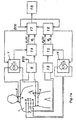
- Fig 1a shows a block diagram of an embodiment of the apparatus for carrying out simultaneous measurements on a patient 1.
- current supply electrodes 2 and 3 current from a current source 7 is supplied to a patient 1.
- the voltage resulting from current passing through the tissue of the test person 1 is measured by means of a pair of electrodes 4 and 5 which are connected with a differential amplifier 6.
- the electrodes 4 and 5 serve for the transversal measurement.
- Current input electrodes 8 and 9 are locally placed on the patient 1 and are connected with current source 12.
- the resulting voltage over the tissue between said electrodes is measured by means of the electrodes 10 and 11 which are connected with differential amplifier 13.
- the electrodes 10 and 11 serve for the local measurement.
- the output of the differential amplifier 6 is fed into a calculating element 14 providing an electric bio-impedance signal Z 1 (t) which is directly related to the bio-impedance of the thorax of the patient 1 as a function of the time and a phase signal ⁇ 1 which is directly related to the phase difference between the current supplied by means of a current source 7 and the voltage measured by electrodes 4 and 5.
- the output of the differential amplifier 13 is supplied to the calculating element 15 which provides an electric bio-impedance signal Z 2 (t) which is directly related to the bio-impedance of a locally measured part of the body as a function of the time and a phase signal ⁇ 2 which is directly related to the phase difference between the current supplied into said part of the body and the resulting voltage over that part of the body as measured by means of the electrodes 10 and 11.
- the electric bio-impedance signal Z 1 (t) and the phase signal ⁇ 1 are fed into a processor 17 in order to determine a parameter to be identified below.
- the frequency and possibly the amplitude of the current source 7 are preferably controlled by the processor 17.
- the electrocardiogram (ECG) obtained at the output side of the differential amplifier 6 or from a separate ECG amplifier (not shown), is fed into the processor 17.
- the signals Z 2 (t) and ⁇ 2 are fed into the processor 16 for the determination of the fluid distribution in the locally measured part of the body.
- the resulting parameters are then fed into the processor 17 for the determination of correction factors in the operations carried out by processor 17.
- the above-mentioned ECG also serves for the improvement of accuracy.
- the output of processor 17 showing the desired parameters, is connected to indicator 18 for display and registration purposes.
- Fig. 1b shows the circuit suitable for sequential measurement on the patient 1.
- the functions of blocks 6, 7, 14, 17 and 18 have already been elucidated.
- the switch 19 is controlled by the processor 17 for carrying out sequential measuring on the thorax bio-impedance and measuring the local bio-impedance of a part of the body of patient 1.
- Fig. 1b shows clearly that in a first situation the current source 7 is connected with the electrodes 2 and 3, while the differential amplifier 6 is at the same time connected with the electrodes 4 and 5 by which measuring of the thorax bio-impedance can then take place. In the other situation said current source is connected with the electrodes 8 and 9, while said differential amplifier 6 is connected with the electrodes 10 and 11 so that local measuring of the bio-impedance of the part of the body of the patient 1 can take place.
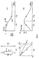
- Fig. 2 shows a typical progress of a bio-impedance signal ⁇ Z, as measured with the differential amplifier 6 based on an excitation by current source 7.
- the progress of this signal is time-dependant in particular because of the pumping activity of the heart of the test person 1.
- the time derivative of the signal ⁇ Z, dZ/dt is shown one row higher in Fig. 2. According to the prior art, when determining the stroke volume of the heart, this is approximated by multiplying the minimum value of the time derivative (dZ/dt) min by a time interval which is determined by the characteristic waveforms in the signal dZ/dt.
- this time interval is indicated as (left) ventricular ejection time (abbreviated (L)VET), and is dependent on a point in time at the beginning of a curve indicated by B and a point in time determined by the next maximum in the time derivative indicated by C.
- L ventricular ejection time
- C electrocardiogram
- measuring errors ensuing due to over- or underweight of the test person 1 or due to measurements carried out under conditions where the normal moisture balance of the test person is upset, for instance with oedema formation are prevented due to the fact that the current source 7 can generate an electric current having at least two frequencies.
- the measuring results becoming available from differential amplifier 6 are converted into a bio-impedance signal Z, while this element 14 also determines the phase difference ⁇ between the current from source 7 and the voltage from amplifier 6.
- the current source 7 can generate a current having frequencies in the range of about 4 kHz to about 2000 kHz; if desired, the current source 7 can simultaneously generate currents having different frequencies.
- the frequency-dependent measuring results for a particular thorax transfer model may be transformed into a current distribution factor which is dependent on the geometry of the test person 1.
- the moisture distribution according to the Cole-Cole-model may be used by means of which a current ratio between the intracellular fluid and the extracellular fluid can be determined. This current ratio corresponds to the current distribution over the cardiovascular system and the rest of the thorax.
- the current source 7 is suitable for the generation of a electric current having a frequency sweep of about 4 kHz to 2000 kHz, while the calculation element 14 is also suitable for the determination of the maximum phase angle dependent on the frequency.
- the moisture distribution can be determined with the aid of a Bode analysis of the transfer model of the thorax by determining the maximum phase angle and possibly the frequency at which this occurs. Normally the maximum phase angle is about 9 to 10° at a frequency of 70 kHz.
- a local impedance measurement can be carried out by means of the electrode pairs 8, 9 and 10, 11.
- the measurement results becoming available through the measuring amplifier 13, together with data from the current source 12 are fed into a calculation element 15, and from these a local impedance value and the phase angle between the current from the source 12 and the voltage from the differential amplifier 13 are determined.
- the measuring data thus derived are further processed in a processor 16 in order to determine the current distribution over the cardiovascular system and the rest of the thorax.
- This measuring signal suffering no interference from the heart's pumping action is subsequently also fed into the processor 17 to compensate the measuring data obtained form the transversal measurement.
- the measuring data thus corrected may then be made available for reading via an indicator 18. If necessary, special operations may be carried out by feeding the ECG signal to the processors 16, 17.
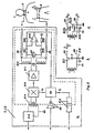
- Fig. 3a shows the block diagram of the current source.
- the current source comprises a floating part which is electrically insulated with respect to its housing.
- a pure sine form whose frequency is controlled by processor 17 is generated by means of the oscillator 212 and is inductively coupled to the floating part of the current source by means of the transformer 214.
- the output of said transformer is fed into a wideband amplifier 210 whose amplification is controlled by the processor 29.
- the output of said amplifier is fed into a wideband capacity amplifier 211, being coupled at its output side via a transformer 215 to the current feed electrodes placed on the patient 1.
- the transformer 215 comprises two analogous secondary windings connected with each other in such a way that a current i can be measured by means of determining the voltage over a precision resistor 27.
- the live cables 25 and 26 are protected in order to reduce the electromagnetic field generated by this cable. However, this protection could cause a problem, because with the increased frequency an increased current resulting from the capacity of these cables, plays a role.
- the wideband amplifier 216 measures the voltage produced at the spot of said precision resistor 27, which data is fed into processor 29 in order to be compared with an amplitude control signal coming, for instance, from processor 17 or from a reference present in the processor 29.
- the processor 29 emits a voltage Vc for the control of the amplification of amplifier 210.
- Vc the amplitude of current i is directly related to the amplitude control signal so that said current is stabilized.
- the amplitude control signal is preferably generated by processor 17.
- processor 29 transforms the voltage over resistor 27 into a reference signal f r for the phase measurement.
- this signal is transmitted galvanically separated.
- an electric apparatus is prone to the development of electromagnetic stray fields.
- Fig. 3b shows a current source according to the prior art, from which can be seen that the amplitude of the parasitic current is determined by the measure of parasitic capacity 217 and the insulation capacity 218.
- the parasitic capacity 217 is determined by the body surface of the patient 1.
- the diagram in Fig. 3c shows the symmetric arrangement according to the invention, as a result of which no voltage is generated over the insulation capacity, with the result that the effective parasitic capacity is reduced.
- Fig. 4 shows a block diagram of the differential amplifiers 6 and 13. Said amplifiers are divided into an electrically insulated part (floating part) comprising a pair of amplifiers 35 consisting of a junction FET 50, 51 and a PHP-transistor 52, 53 arranged symmetrically.
- the emission resistor 36 and the decoupling capacity 37 form a time constant ⁇ .
- the signal present on these emitters is passed on via the insulation amplifier 33.
- the circuit behaves like a differencial source follower connected with the transformer 31.
- the current input side serves as an amplifier for the electrocardiogram signal since this signal holds frequency to about 100 Hz, being well below f c .
- the circuit serves as input side impedance transformer for the bio-impedance measurement for the conduction of the high frequency signal measured at the location of the electrodes 4 and 5, to transformer 31.
- Said transformer conducts the signal over the galvanic separation to the amplifier 32 and realizes at the same time an impedance matching.
- the circuit shown with current source 30 in combination with the floating input results in suppression of common mode signals at the location of the measuring electrodes.
- Fig. 5 shows the determination of the frequency behaviour of the Cole-Cole model with the aid of Bode analysis.
- Fig. 5 shows the actual Cole-Cole model, the vector diagram of current and voltages and the amplitude and phase diagrams as a function of the frequency.
- the maximum phase angle ⁇ max depends on the ratio ⁇ 2 / ⁇ 1 and occurs at frequency ⁇ m .
- Fig. 6 shows a block diagram of a typical embodiment of the transformers 14 and 15.
- the signal from the amplifier 32 (see Fig. 4) is fed into a device 40 passing the signal to a demodulator formed by the amplifiers 42, 43 and 44, and a carrier regeneration oscillator 41 based on a phase-locked loop. Said oscillator adapts its frequency dependent on the signal received from device 40 such that no phase shift ensues.
- the output of oscillator 41 is used for the synchronized connection between the outputs of the amplifiers 42 and 43 in order to obtain complete rectification of the signal at the input of said amplifiers.
- the output of the oscillator 41 is fed into a phase detector 46 for measuring the phase difference between the signal input of device 40 and a reference signal REF obtained from the optocoupler 28 (see Fig. 3) which depends directly on the current passing through the electrodes 2 and 3.
- the output of the detector 46 is fed through a low-pass filter 47, which low-pass filter 47 in itself is known, in order to obtain a signal which is directly related to the phase difference between the current input provided by current source 7, 12 and the voltage measured by means of the differential amplifier 6, 13.
- the bio-impedance signal Z(t) is obtained by feeding the output from amplifier 44 through a low-pass filter 45, which low-pass filter 45 in itself is known.
Landscapes
- Health & Medical Sciences (AREA)
- Life Sciences & Earth Sciences (AREA)
- Medical Informatics (AREA)
- Animal Behavior & Ethology (AREA)
- Veterinary Medicine (AREA)
- Biophysics (AREA)
- Pathology (AREA)
- Engineering & Computer Science (AREA)
- Biomedical Technology (AREA)
- Heart & Thoracic Surgery (AREA)
- Public Health (AREA)
- Molecular Biology (AREA)
- Surgery (AREA)
- Physics & Mathematics (AREA)
- General Health & Medical Sciences (AREA)
- Nuclear Medicine, Radiotherapy & Molecular Imaging (AREA)
- Radiology & Medical Imaging (AREA)
- Hematology (AREA)
- Cardiology (AREA)
- Physiology (AREA)
- Measurement Of The Respiration, Hearing Ability, Form, And Blood Characteristics Of Living Organisms (AREA)
- Measurement And Recording Of Electrical Phenomena And Electrical Characteristics Of The Living Body (AREA)
- Investigating Or Analysing Biological Materials (AREA)
Claims (11)
- Eine Vorrichtung zur nicht-invasiven in-vivo-Messung eines biologischen Parameters hinsichtlich eines Körperfluids einer Person (1) oder eines Tiers gemäß einem Rechenmodell, wobei die Vorrichtung mit zumindest zwei Paaren von Elektroden (2, 3, 4, 5, 8, 9, 10, 11) versehen ist, die auf der Haut eines Körperteils zu plazieren sind, und die aus einem Paar von Eingangselektroden (2, 3, 8, 9) zum Zuführen eines Meßwechselstroms zu dem Körperteil und einem Meßpaar (4, 5, 10, 11) von Elektroden zum Messen der Spannung an den Elektroden des Meßpaars von Elektroden bestehen, wobei die Vorrichtung ferner eine Stromquelle (7, 12), die den Meßwechselstrom liefert, einen Konverter (14, 15) für die Umwandlung der Meßspannung und des Meßstroms in ein Bioimpedanzsignal, das ein Maß für die Bioimpedanz des Körperteils ist, und eine Einrichtung für die Erzeugung von Signalen aufweist, die ein Maß für weitere Variablen bilden, mit deren Hilfe der Parameter unter Verwendung des Rechenmodells bestimmt werden kann, wobei die Signale ein Signal umfassen, das ein Maß für die Zeitableitung des Bioimpedanzsignals bildet, dadurch gekennzeichnet, daß die Stromquelle (7, 12) oder Stromquellen (7, 14) elektrisch symmetrisch konfiguriert und galvanisch hinsichtlich der Instrumentenmasse getrennt sind und geeignet zum Erzeugen eines Meßstroms ist oder sind, der bei zumindest zwei Frequenzen, nämlich einer niedrigen Frequenz und einer hohen Frequenz, in einem Frequenzbereich von bis zu 2000 kHz eine konstante Amplitude aufweist.
- Eine Vorrichtung gemäß Anspruch 1, dadurch gekennzeichnet, daß der Parameter ein Kreislaufparameter des Herzens ist.
- Eine Vorrichtung gemäß Anspruch 1 oder 2, dadurch gekennzeichnet, daß der Parameter das Schlagvolumen des Herzens ist.
- Eine Vorrichtung gemäß einem der vorhergehenden Ansprüche, dadurch gekennzeichnet, daß die niedrige Frequenz f l in dem Bereich von etwa 1 bis 64 kHz und die hohe Frequenz f h in dem Bereich von etwa 32 bis 2000 kHz liegt, derart, daß in jedem Fall f l kleiner als f h ist.
- Eine Vorrichtung gemäß einem der Ansprüche 1 bis 4, dadurch gekennzeichnet, daß die Stromquelle (7, 12) geeignet zur gleichzeitigen Erzeugung der beiden Frequenzen ist.
- Eine Vorrichtung gemäß einem der Ansprüche 1 bis 5, dadurch gekennzeichnet, daß die Vorrichtung mit vier Paaren von Elektroden (2, 3; 4, 5; 8, 9; 10, 11) versehen ist, von denen zwei Paare als Eingangselektrodenpaar (2, 3) und ein Meßelektrodenpaar (4, 5) zum Nehmen der transversalen Bioimpedanzmessung bei einer niedrigen und einer hohen Frequenz dienen und zwei weitere Paare als ein Eingangselektrodenpaar (8, 9) und ein Meßelektrodenpaar (10, 11) zum Nehmen einer lokalen Bioimpedanzmessung bei einer niedrigen und einer hohen Frequenz dienen.
- Eine Vorrichtung gemäß Anspruch 6, dadurch gekennzeichnet, daß die Vorrichtung mit einer Verbindungseinrichtung (19) zum In-Serie-Schalten der Stromquelle (7) und des Wandlers (6, 14) versehen ist, um die lokale Bioimpedanzmessung und die transversale Bioimpedanzmessung nacheinander auszuführen.
- Eine Vorrichtung gemäß Anspruch 6, dadurch gekennzeichnet, daß die Vorrichtung eine Stromquelle oder Stromquellen (7, 12) aufweist, die geeignet für die gleichzeitige Erzeugung von Signalen bei zwei niedrigen Frequenzen und zwei hohen Frequenzen sind.
- Eine Vorrichtung gemäß einem der vorhergehenden Ansprüche, dadurch gekennzeichnet, daß die Einrichtung (14, 15) für die Bestimmung der maximalen Phasenverschiebung zwischen dem Meßstrom und der Meßspannung als eine Funktion der Frequenz vorgesehen ist.
- Eine Vorrichtung gemäß einem der vorhergehende Ansprüche, dadurch gekennzeichnet, daß der Meßverstärker (6) für die Verstärkung der Meßspannung elektrisch symmetrisch konfiguriert ist und mit einer galvanischen Trennung hinsichtlich der Instrumentenerde versehen ist.
- Eine Vorrichtung gemäß Anspruch 10, dadurch gekennzeichnet, daß der Meßverstärker (6) mit einer galvanischen Trennung (31) von einer Testperson (1) versehen ist, die mit der Vorrichtung verbunden werden soll.
Applications Claiming Priority (3)
| Application Number | Priority Date | Filing Date | Title |
|---|---|---|---|
| NL1001282 | 1995-09-26 | ||
| NL1001282A NL1001282C2 (nl) | 1995-09-26 | 1995-09-26 | Inrichting voor slagvolumebepaling van een menselijk hart. |
| PCT/NL1996/000374 WO1997011638A2 (en) | 1995-09-26 | 1996-09-25 | Apparatus for the in-vivo non-invasive measurement of a biological parameter concerning a bodily fluid of a person or animal |
Publications (2)
| Publication Number | Publication Date |
|---|---|
| EP0855875A2 EP0855875A2 (de) | 1998-08-05 |
| EP0855875B1 true EP0855875B1 (de) | 2002-08-28 |
Family
ID=19761625
Family Applications (1)
| Application Number | Title | Priority Date | Filing Date |
|---|---|---|---|
| EP96932860A Expired - Lifetime EP0855875B1 (de) | 1995-09-26 | 1996-09-25 | Gerät zur invivo nichtinvasiven messung eines biologischen parameters von einer körperflüssigkeit einer person oder eines tieres |
Country Status (11)
| Country | Link |
|---|---|
| US (1) | US6339722B1 (de) |
| EP (1) | EP0855875B1 (de) |
| JP (1) | JP3935937B2 (de) |
| AT (1) | ATE222726T1 (de) |
| AU (1) | AU7146996A (de) |
| DE (1) | DE69623304T2 (de) |
| ES (1) | ES2183010T3 (de) |
| IL (1) | IL123763A (de) |
| NL (1) | NL1001282C2 (de) |
| NO (1) | NO325522B1 (de) |
| WO (1) | WO1997011638A2 (de) |
Cited By (3)
| Publication number | Priority date | Publication date | Assignee | Title |
|---|---|---|---|---|
| DE102005031752A1 (de) * | 2005-07-07 | 2007-01-18 | Dräger Medical AG & Co. KG | Elektroimpedanztomographie-Gerät mit Gleichtaktsignalunterdrückung |
| DE102005031751A1 (de) * | 2005-07-07 | 2007-01-18 | Dräger Medical AG & Co. KG | Elektroimpedanztomographie-Gerät mit Gleichtaktsignalunterdrückung |
| EP3558108B1 (de) * | 2016-12-26 | 2025-12-10 | Bioserenity | Störungsanzeige für eine wearable-vorrichtung |
Families Citing this family (105)
| Publication number | Priority date | Publication date | Assignee | Title |
|---|---|---|---|---|
| AUPQ113799A0 (en) * | 1999-06-22 | 1999-07-15 | University Of Queensland, The | A method and device for measuring lymphoedema |
| AU2001263239A1 (en) * | 2000-05-18 | 2001-11-26 | Nuvasive, Inc. | Tissue discrimination and applications in medical procedures |
| RU2177717C1 (ru) * | 2000-07-31 | 2002-01-10 | Закрытое акционерное общество "Руссоком" | Способ измерения электрических параметров кожных и слизистых покровов и устройство для его осуществления |
| JP3977983B2 (ja) * | 2000-07-31 | 2007-09-19 | 株式会社タニタ | 生体インピーダンス測定による脱水状態判定装置 |
| FI109651B (fi) * | 2001-03-23 | 2002-09-30 | Delfin Technologies Ltd | Menetelmä kudosturvotuksen mittaamiseksi |
| US6631292B1 (en) * | 2001-03-23 | 2003-10-07 | Rjl Systems, Inc. | Bio-electrical impedance analyzer |
| US7044911B2 (en) * | 2001-06-29 | 2006-05-16 | Philometron, Inc. | Gateway platform for biological monitoring and delivery of therapeutic compounds |
| WO2003003920A2 (en) * | 2001-07-05 | 2003-01-16 | Gennady Gedevanishvili | Method and device for non-invasive research of blood distribution and its circulatory characteristics in warm-blooded organism |
| US7664544B2 (en) | 2002-10-30 | 2010-02-16 | Nuvasive, Inc. | System and methods for performing percutaneous pedicle integrity assessments |
| NL1019788C2 (nl) | 2002-01-18 | 2003-07-21 | A J Van Liebergen Holding B V | Werkwijze voor het elektronisch meten van een parameter van bijvoorbeeld een (electro-)mechanisch systeem of van een menselijk lichaam. |
| NL1019789C2 (nl) | 2002-01-18 | 2003-07-21 | A J Van Liebergen Holding B V | Samenstel van een connector en een van de connector losneembare elektrode alsmede de losse connector en losse elektrode. |
| US7050847B2 (en) | 2002-03-26 | 2006-05-23 | Stig Ollmar | Non-invasive in vivo determination of body fluid parameter |
| AU2002951925A0 (en) * | 2002-10-09 | 2002-10-24 | Queensland University Of Technology | An Impedence Cardiography Device |
| CA2537451A1 (en) * | 2002-11-22 | 2004-06-10 | Impedimed Pty Limited | Multifrequency bioimpedance determination |
| JP2004255120A (ja) * | 2003-02-28 | 2004-09-16 | Tanita Corp | 体組成推定法及び体組成測定装置 |
| WO2004082460A2 (en) * | 2003-03-14 | 2004-09-30 | Shock, Llc | Methods of and apparatus for determining fluid volume presence in mammalian tissue |
| US20040225228A1 (en) | 2003-05-08 | 2004-11-11 | Ferree Bret A. | Neurophysiological apparatus and procedures |
| US8414498B2 (en) | 2003-05-12 | 2013-04-09 | Cheetah Medical, Inc. | System, method and apparatus for measuring blood flow and blood volume |
| CA2539547A1 (en) * | 2003-08-20 | 2005-03-03 | Philometron, Inc. | Hydration monitoring |
| US20050272891A1 (en) * | 2004-02-13 | 2005-12-08 | Atofina Research S.A. | Double loop technology |
| CA2578106C (en) * | 2004-06-18 | 2015-09-01 | The University Of Queensland | Oedema detection |
| US8068906B2 (en) | 2004-06-21 | 2011-11-29 | Aorora Technologies Pty Ltd | Cardiac monitoring system |
| JP2008503277A (ja) * | 2004-06-21 | 2008-02-07 | オーロラ・テクノロジーズ・プロプライエタリー・リミテッド | 心臓モニタシステム |
| WO2006029035A1 (en) * | 2004-09-02 | 2006-03-16 | Philometron, Inc. | Monitoring platform for wound and ulcer monitoring and detection |
| US8103337B2 (en) * | 2004-11-26 | 2012-01-24 | Impedimed Limited | Weighted gradient method and system for diagnosing disease |
| US8109981B2 (en) * | 2005-01-25 | 2012-02-07 | Valam Corporation | Optical therapies and devices |
| CN101160091B (zh) * | 2005-02-15 | 2010-07-14 | 奇塔医疗有限公司 | 用于测量血流和血容量的系统、方法和设备 |
| CN1319490C (zh) * | 2005-07-01 | 2007-06-06 | 天津大学 | 模拟解调方式的混频生物阻抗测量系统 |
| AU2006265763B2 (en) * | 2005-07-01 | 2012-08-09 | Impedimed Limited | Monitoring system |
| JP5034028B2 (ja) * | 2005-07-01 | 2012-09-26 | インペダイムド・リミテッド | 肺モニタリングシステム |
| CN100333689C (zh) * | 2005-07-01 | 2007-08-29 | 天津大学 | 模拟解调方式的混频生物阻抗测量方法 |
| CA2608962C (en) * | 2005-07-01 | 2016-12-06 | Scott Chetham | Monitoring system |
| WO2007009183A1 (en) * | 2005-07-20 | 2007-01-25 | Impedance Cardiology Systems, Inc. | Index determination |
| EP1912563B1 (de) * | 2005-08-02 | 2016-04-20 | Impedimed Limited | Impedanzparameter-werte |
| WO2007041783A1 (en) | 2005-10-11 | 2007-04-19 | Impedance Cardiology Systems, Inc. | Hydration status monitoring |
| AT502921B1 (de) * | 2005-10-21 | 2012-01-15 | Falko Dr Skrabal | Gerät zur messung von herz- und gefässfunktion (function) und körperräumen (spaces) mit hilfe der impedanzmessung |
| US8600497B1 (en) | 2006-03-31 | 2013-12-03 | Pacesetter, Inc. | Systems and methods to monitor and treat heart failure conditions |
| JP5431147B2 (ja) | 2006-05-30 | 2014-03-05 | インぺディメッド リミテッド | インピーダンス測定 |
| KR101498305B1 (ko) | 2006-09-05 | 2015-03-03 | 엔. 아이. 메디컬 엘티디. | 심장 지표들의 비침습적 측정을 위한 방법 및 시스템 |
| CA2663897C (en) * | 2006-09-19 | 2015-01-06 | Gambro Lundia Ab | Estimation of propensity to symptomatic hypotension |
| CA2670293C (en) | 2006-11-30 | 2017-01-03 | Impedimed Limited | Measurement apparatus |
| WO2008086565A1 (en) * | 2007-01-15 | 2008-07-24 | Impedimed Limited | Monitoring system |
| US9095271B2 (en) * | 2007-08-13 | 2015-08-04 | Cheetah Medical, Inc. | Dynamically variable filter |
| US8876725B2 (en) * | 2007-02-23 | 2014-11-04 | Cheetah Medical, Inc. | Method and system for estimating exercise capacity |
| EP2131737B1 (de) * | 2007-03-07 | 2015-04-29 | Cheetah Medical, Inc. | Verfahren und system zur überwachung des schlafes |
| US8487686B2 (en) * | 2007-03-30 | 2013-07-16 | Impedimed Limited | Active guarding for reduction of resistive and capacitive signal loading with adjustable control of compensation level |
| CA2683684C (en) * | 2007-04-19 | 2016-02-02 | Cheetah Medical Ltd. | Method, apparatus and system for predicting electromechanical dissociation |
| EP2148613B9 (de) | 2007-04-20 | 2014-12-10 | Impedimed Limited | Überwachungssystem und sonde |
| CN100571612C (zh) * | 2007-07-13 | 2009-12-23 | 深圳迪美泰数字医学技术有限公司 | 用于临床或非临床生物信号记录的纯数字医用放大器 |
| EP2175776B1 (de) | 2007-08-09 | 2016-03-23 | Impedimed Limited | Impedanz-messverfahren |
| USD625823S1 (en) | 2007-08-30 | 2010-10-19 | Cheetah Medical Ltd. | Electrode |
| US9186089B2 (en) | 2007-09-14 | 2015-11-17 | Medtronic Monitoring, Inc. | Injectable physiological monitoring system |
| US20090076350A1 (en) * | 2007-09-14 | 2009-03-19 | Corventis, Inc. | Data Collection in a Multi-Sensor Patient Monitor |
| EP2194847A1 (de) | 2007-09-14 | 2010-06-16 | Corventis, Inc. | Haftende vorrichtung mit mehreren physiologischen sensoren |
| WO2009036333A1 (en) * | 2007-09-14 | 2009-03-19 | Corventis, Inc. | Dynamic pairing of patients to data collection gateways |
| WO2009036327A1 (en) * | 2007-09-14 | 2009-03-19 | Corventis, Inc. | Adherent device for respiratory monitoring and sleep disordered breathing |
| WO2009036334A1 (en) * | 2007-09-14 | 2009-03-19 | Corventis, Inc. | Adherent multi-sensor device with empathic monitoring |
| EP2200499B1 (de) * | 2007-09-14 | 2019-05-01 | Medtronic Monitoring, Inc. | Multi-sensor-patientenmonitor zum nachweis von bevorstehender herzdekompensation |
| US20090076341A1 (en) * | 2007-09-14 | 2009-03-19 | Corventis, Inc. | Adherent Athletic Monitor |
| US20090076397A1 (en) * | 2007-09-14 | 2009-03-19 | Corventis, Inc. | Adherent Emergency Patient Monitor |
| WO2009036348A1 (en) * | 2007-09-14 | 2009-03-19 | Corventis, Inc. | Medical device automatic start-up upon contact to patient tissue |
| WO2009036306A1 (en) | 2007-09-14 | 2009-03-19 | Corventis, Inc. | Adherent cardiac monitor with advanced sensing capabilities |
| US20090076559A1 (en) * | 2007-09-14 | 2009-03-19 | Corventis, Inc. | Adherent Device for Cardiac Rhythm Management |
| EP2211714B1 (de) * | 2007-11-05 | 2016-11-23 | Impedimed Limited | Nachweis der impedanz |
| AU2008207672B2 (en) * | 2008-02-15 | 2013-10-31 | Impedimed Limited | Impedance Analysis |
| JP5405500B2 (ja) * | 2008-03-12 | 2014-02-05 | コーヴェンティス,インク. | 心調律に基づく心代償不全予測 |
| US8412317B2 (en) * | 2008-04-18 | 2013-04-02 | Corventis, Inc. | Method and apparatus to measure bioelectric impedance of patient tissue |
| WO2009131664A2 (en) * | 2008-04-21 | 2009-10-29 | Carl Frederick Edman | Metabolic energy monitoring system |
| US20090270756A1 (en) * | 2008-04-23 | 2009-10-29 | Gamache Ronald W | Determining physiological characteristics of animal |
| US20100191310A1 (en) * | 2008-07-29 | 2010-07-29 | Corventis, Inc. | Communication-Anchor Loop For Injectable Device |
| CN102159132B (zh) * | 2008-09-22 | 2015-11-25 | 奇塔医疗公司 | 用于确定血流的系统和方法 |
| US20100081915A1 (en) * | 2008-09-29 | 2010-04-01 | Searete Llc, Alimited Liability Corporation Of The State Of Delaware | Histological facilitation systems and methods |
| US20100081926A1 (en) * | 2008-09-29 | 2010-04-01 | Searete Llc, A Limited Liability Corporation Of The State Of Delaware | Histological facilitation systems and methods |
| US20100081916A1 (en) * | 2008-09-29 | 2010-04-01 | Searete Llc, A Limited Liability Corporation Of The State Of Delaware. | Histological facilitation systems and methods |
| US20100081927A1 (en) * | 2008-09-29 | 2010-04-01 | Searete Llc, A Limited Liability Corporation Of The State Of Delaware | Histological facilitation systems and methods |
| US20100081928A1 (en) * | 2008-09-29 | 2010-04-01 | Searete Llc, A Limited Liability Corporation Of The State Of Delaware | Histological Facilitation systems and methods |
| US20100081924A1 (en) * | 2008-09-29 | 2010-04-01 | Searete Llc, A Limited Liability Corporation Of The State Of Delaware | Histological facilitation systems and methods |
| EP2348987B1 (de) | 2008-11-28 | 2017-03-22 | Impedimed Limited | Impedanz-messverfahren |
| CZ2008802A3 (cs) * | 2008-12-15 | 2010-06-23 | Ústav prístrojové techniky AV CR, v.v.i. | Zarízení pro merení vlastností toku krve a zpusob jeho pripojení |
| DE112010001220A5 (de) * | 2009-03-20 | 2012-07-05 | Technische Universität Berlin | Messsystem zur beurteilung des schluckvorgangs und/oder bestimmung der aspiration |
| CA2764637C (en) | 2009-06-09 | 2018-03-20 | Biosensors, Inc. | Non-invasive monitoring of blood metabolite levels |
| WO2011050283A2 (en) | 2009-10-22 | 2011-04-28 | Corventis, Inc. | Remote detection and monitoring of functional chronotropic incompetence |
| WO2011050393A1 (en) | 2009-10-26 | 2011-05-05 | Impedimed Limited | Fluid level indicator determination |
| WO2011060497A1 (en) | 2009-11-18 | 2011-05-26 | Impedimed Limited | Signal distribution for patient-electrode measurements |
| US9451897B2 (en) * | 2009-12-14 | 2016-09-27 | Medtronic Monitoring, Inc. | Body adherent patch with electronics for physiologic monitoring |
| WO2011112972A2 (en) * | 2010-03-11 | 2011-09-15 | Philometron, Inc. | Physiological monitor system for determining medication delivery and outcome |
| US8965498B2 (en) | 2010-04-05 | 2015-02-24 | Corventis, Inc. | Method and apparatus for personalized physiologic parameters |
| DE102010028902A1 (de) * | 2010-05-11 | 2011-11-17 | Fresenius Medical Care Deutschland Gmbh | Verfahren und Vorrichtung zur Bestimmung zellulärer und/oder extrazellulärer, insbesondere makromolekularer Anteile von Flüssigkeiten, vorzugsweise von Körperflüssigkeiten von Lebewesen |
| JP2015512658A (ja) | 2011-12-14 | 2015-04-30 | インターセクション・メディカル・インコーポレイテッドIntersection Medical,Inc. | 組織内の周波数に対する表面下抵抗率の相対的空間変化を決定するためのデバイス、システム及び方法 |
| JP5694139B2 (ja) * | 2011-12-28 | 2015-04-01 | 日本光電工業株式会社 | 睡眠中における無呼吸低呼吸状態の検出装置 |
| WO2013126788A1 (en) * | 2012-02-22 | 2013-08-29 | Bomed Inc. | System for detection and processing of electrical bioimpedance signals in an animal or human segment |
| WO2014059308A2 (en) * | 2012-10-12 | 2014-04-17 | Cardioinsight Technologies, Inc. | Medical amplifier isolation |
| AT514017B1 (de) | 2013-02-22 | 2020-11-15 | Dr Skrabal Falko | Hämodynamisches EKG |
| US9113805B2 (en) | 2013-03-04 | 2015-08-25 | Mortara Instrument, Inc. | Impedance measurement system |
| US9591987B1 (en) | 2013-08-23 | 2017-03-14 | Rjl Systems, Inc. | Determining body composition through segmental bioelectrical impedance analysis (BIA) |
| RU2586457C1 (ru) * | 2015-02-25 | 2016-06-10 | Федеральное государственное бюджетное образовательное учреждение высшего профессионального образования "Тамбовский государственный технический университет" ФГБОУ ВПО ТГТУ | Способ определения составляющих импеданса биообъекта |
| AT516499B1 (de) | 2015-04-22 | 2016-06-15 | Skrabal Falko Dr | Körperimpedanz-Messgerät |
| WO2016177901A1 (en) | 2015-05-06 | 2016-11-10 | National University Of Ireland, Galway | Non-invasive detection of the backflow of urine |
| TWI598073B (zh) * | 2016-12-15 | 2017-09-11 | 財團法人工業技術研究院 | 生理訊號量測方法及生理訊號量測裝置 |
| RU2669484C1 (ru) * | 2017-06-27 | 2018-10-11 | Федеральное государственное бюджетное образовательное учреждение высшего образования "Тамбовский государственный технический университет" (ФГБОУ ВО "ТГТУ") | Способ определения составляющих импеданса биообъекта |
| EP3957240B1 (de) * | 2019-04-15 | 2024-11-06 | Msheaf Health Management Technologies Limited | Nichtinvasives verfahren und system zur detektion von merkmalsinformationen von in-vivo-gewebe |
| WO2020211051A1 (zh) * | 2019-04-18 | 2020-10-22 | 麦层移动健康管理有限公司 | 一种测量心肌组织运动特征的非侵入性方法及系统 |
| DE102020003524B4 (de) * | 2020-06-12 | 2023-03-23 | Coco Beteiligungsgesellschaft mbH | Überwachungseinheit und Hochfrequenz-Chirurgiesystem mit einer solchen Überwachungseinheit |
| IT202100010775A1 (it) | 2021-04-28 | 2022-10-28 | Roni Shabat | Sistemi e metodi per la determinazione dell'impedenza polmonare |
| US12551160B2 (en) * | 2021-07-22 | 2026-02-17 | Nfant Labs, Inc. | System and method for measuring human milk production |
Family Cites Families (5)
| Publication number | Priority date | Publication date | Assignee | Title |
|---|---|---|---|---|
| WO1990000367A1 (en) * | 1988-07-14 | 1990-01-25 | Bomed Medical Manufacturing, Ltd. | Management of hemodynamic state of a patient |
| US5423326A (en) * | 1991-09-12 | 1995-06-13 | Drexel University | Apparatus and method for measuring cardiac output |
| IL102300A (en) * | 1992-06-24 | 1996-07-23 | N I Medical Ltd | Non-invasive system for determining of the main cardiorespiratory parameters of the human body |
| US5807272A (en) * | 1995-10-31 | 1998-09-15 | Worcester Polytechnic Institute | Impedance spectroscopy system for ischemia monitoring and detection |
| US5685316A (en) * | 1996-04-08 | 1997-11-11 | Rheo-Graphic Pte Ltd. | Non-invasive monitoring of hemodynamic parameters using impedance cardiography |
-
1995
- 1995-09-26 NL NL1001282A patent/NL1001282C2/nl not_active IP Right Cessation
-
1996
- 1996-09-25 JP JP51331197A patent/JP3935937B2/ja not_active Expired - Fee Related
- 1996-09-25 US US09/043,864 patent/US6339722B1/en not_active Expired - Fee Related
- 1996-09-25 EP EP96932860A patent/EP0855875B1/de not_active Expired - Lifetime
- 1996-09-25 ES ES96932860T patent/ES2183010T3/es not_active Expired - Lifetime
- 1996-09-25 AU AU71469/96A patent/AU7146996A/en not_active Abandoned
- 1996-09-25 IL IL12376396A patent/IL123763A/xx not_active IP Right Cessation
- 1996-09-25 WO PCT/NL1996/000374 patent/WO1997011638A2/en not_active Ceased
- 1996-09-25 AT AT96932860T patent/ATE222726T1/de not_active IP Right Cessation
- 1996-09-25 DE DE69623304T patent/DE69623304T2/de not_active Expired - Fee Related
-
1998
- 1998-03-23 NO NO19981304A patent/NO325522B1/no unknown
Cited By (6)
| Publication number | Priority date | Publication date | Assignee | Title |
|---|---|---|---|---|
| DE102005031752A1 (de) * | 2005-07-07 | 2007-01-18 | Dräger Medical AG & Co. KG | Elektroimpedanztomographie-Gerät mit Gleichtaktsignalunterdrückung |
| DE102005031751A1 (de) * | 2005-07-07 | 2007-01-18 | Dräger Medical AG & Co. KG | Elektroimpedanztomographie-Gerät mit Gleichtaktsignalunterdrückung |
| US7941210B2 (en) | 2005-07-07 | 2011-05-10 | Dräger Medical GmbH | Electroimpedance tomograph with common-mode signal suppression |
| DE102005031751B4 (de) * | 2005-07-07 | 2017-09-14 | Drägerwerk AG & Co. KGaA | Elektroimpedanztomographie-Gerät mit Gleichtaktsignalunterdrückung |
| DE102005031752B4 (de) * | 2005-07-07 | 2017-11-02 | Drägerwerk AG & Co. KGaA | Elektroimpedanztomographie-Gerät mit Gleichtaktsignalunterdrückung |
| EP3558108B1 (de) * | 2016-12-26 | 2025-12-10 | Bioserenity | Störungsanzeige für eine wearable-vorrichtung |
Also Published As
| Publication number | Publication date |
|---|---|
| NO981304D0 (no) | 1998-03-23 |
| NO325522B1 (no) | 2008-06-02 |
| ATE222726T1 (de) | 2002-09-15 |
| IL123763A0 (en) | 1998-10-30 |
| DE69623304T2 (de) | 2003-07-31 |
| ES2183010T3 (es) | 2003-03-16 |
| JPH11511371A (ja) | 1999-10-05 |
| WO1997011638A3 (en) | 1997-05-29 |
| WO1997011638A2 (en) | 1997-04-03 |
| JP3935937B2 (ja) | 2007-06-27 |
| IL123763A (en) | 2003-04-10 |
| US6339722B1 (en) | 2002-01-15 |
| EP0855875A2 (de) | 1998-08-05 |
| DE69623304D1 (de) | 2002-10-02 |
| NO981304L (no) | 1998-05-15 |
| NL1001282C2 (nl) | 1997-03-28 |
| AU7146996A (en) | 1997-04-17 |
Similar Documents
| Publication | Publication Date | Title |
|---|---|---|
| EP0855875B1 (de) | Gerät zur invivo nichtinvasiven messung eines biologischen parameters von einer körperflüssigkeit einer person oder eines tieres | |
| US5203344A (en) | Method and apparatus for taking bioelectrical impedance measurements using proximally positioned electrodes | |
| JP2875137B2 (ja) | 心肺のパラメーターを決定する非侵入的医学的装置 | |
| US20060247543A1 (en) | High resoution bio-impedance device | |
| US8911379B2 (en) | Method and system for non-invasive measurement of cardiac parameters | |
| US6016445A (en) | Method and apparatus for electrode and transthoracic impedance estimation | |
| US7806830B2 (en) | Apparatus and method for determination of stroke volume using the brachial artery | |
| US4548211A (en) | Computer assisted admittance plethysmograph | |
| US7261697B2 (en) | Apparatus for determination of stroke volume using the brachial artery | |
| US3730171A (en) | Impedance related blood flow measuring device | |
| JP2789486B2 (ja) | 追跡型多電極電子声門グラフと被検体の喉頭の移動状態の検出方法 | |
| US7147601B2 (en) | Signal averaging using gating signal obtained from autocorrelation of input signals | |
| US10709350B2 (en) | Body impedance measuring device | |
| US6058325A (en) | Method and apparatus for high current electrode, transthoracic and transmyocardial impedance estimation | |
| US6253103B1 (en) | Method and apparatus for high current electrode, transthoracic and transmyocardial impedance estimation | |
| Zambrano et al. | Comparative responses to orthostatic stress in normal and abnormal subjects: evaluation by impedance cardiography | |
| KR100321261B1 (ko) | 심박출량과 심전도를 모니터링하기 위한 전극 설치 방법 및 이를 이용한 장치 | |
| RU2664633C2 (ru) | Устройство для измерения электрического импеданса в частях тела | |
| Goovaerts et al. | An electrically isolated balanced wideband current source: basic considerations and design | |
| RU2242165C1 (ru) | Устройство для измерения электрического импеданса в частях тела | |
| RU2134533C1 (ru) | Устройство для определения кожного кровотока | |
| RU2134059C1 (ru) | Способ определения ударного объема сердца | |
| AU2003266844A1 (en) | High resolution bio-impedance device | |
| Pospisilik et al. | Contactless ECG scanning device hardware design proposal | |
| Ghoreishi | A MORPHOLOGICAL STUDY IN ELECTRICAL IMPEDANCE CARDIOGRAPHY AND DISPLACEMENT CARDIOGRAPHY (CARDIOGRAPHY, BLOOD FLOW, HEART) |
Legal Events
| Date | Code | Title | Description |
|---|---|---|---|
| PUAI | Public reference made under article 153(3) epc to a published international application that has entered the european phase |
Free format text: ORIGINAL CODE: 0009012 |
|
| 17P | Request for examination filed |
Effective date: 19980320 |
|
| AK | Designated contracting states |
Kind code of ref document: A2 Designated state(s): AT BE CH DE DK ES FI FR GB IT LI NL SE |
|
| 17Q | First examination report despatched |
Effective date: 20011022 |
|
| GRAG | Despatch of communication of intention to grant |
Free format text: ORIGINAL CODE: EPIDOS AGRA |
|
| GRAG | Despatch of communication of intention to grant |
Free format text: ORIGINAL CODE: EPIDOS AGRA |
|
| GRAH | Despatch of communication of intention to grant a patent |
Free format text: ORIGINAL CODE: EPIDOS IGRA |
|
| GRAH | Despatch of communication of intention to grant a patent |
Free format text: ORIGINAL CODE: EPIDOS IGRA |
|
| GRAA | (expected) grant |
Free format text: ORIGINAL CODE: 0009210 |
|
| AK | Designated contracting states |
Kind code of ref document: B1 Designated state(s): AT BE CH DE DK ES FI FR GB IT LI NL SE |
|
| PG25 | Lapsed in a contracting state [announced via postgrant information from national office to epo] |
Ref country code: LI Free format text: LAPSE BECAUSE OF FAILURE TO SUBMIT A TRANSLATION OF THE DESCRIPTION OR TO PAY THE FEE WITHIN THE PRESCRIBED TIME-LIMIT Effective date: 20020828 Ref country code: FI Free format text: LAPSE BECAUSE OF FAILURE TO SUBMIT A TRANSLATION OF THE DESCRIPTION OR TO PAY THE FEE WITHIN THE PRESCRIBED TIME-LIMIT Effective date: 20020828 Ref country code: CH Free format text: LAPSE BECAUSE OF FAILURE TO SUBMIT A TRANSLATION OF THE DESCRIPTION OR TO PAY THE FEE WITHIN THE PRESCRIBED TIME-LIMIT Effective date: 20020828 Ref country code: AT Free format text: LAPSE BECAUSE OF FAILURE TO SUBMIT A TRANSLATION OF THE DESCRIPTION OR TO PAY THE FEE WITHIN THE PRESCRIBED TIME-LIMIT Effective date: 20020828 |
|
| REF | Corresponds to: |
Ref document number: 222726 Country of ref document: AT Date of ref document: 20020915 Kind code of ref document: T |
|
| REG | Reference to a national code |
Ref country code: GB Ref legal event code: FG4D |
|
| REG | Reference to a national code |
Ref country code: CH Ref legal event code: EP |
|
| REF | Corresponds to: |
Ref document number: 69623304 Country of ref document: DE Date of ref document: 20021002 |
|
| PG25 | Lapsed in a contracting state [announced via postgrant information from national office to epo] |
Ref country code: SE Free format text: LAPSE BECAUSE OF FAILURE TO SUBMIT A TRANSLATION OF THE DESCRIPTION OR TO PAY THE FEE WITHIN THE PRESCRIBED TIME-LIMIT Effective date: 20021128 Ref country code: DK Free format text: LAPSE BECAUSE OF FAILURE TO SUBMIT A TRANSLATION OF THE DESCRIPTION OR TO PAY THE FEE WITHIN THE PRESCRIBED TIME-LIMIT Effective date: 20021128 |
|
| REG | Reference to a national code |
Ref country code: CH Ref legal event code: PL |
|
| REG | Reference to a national code |
Ref country code: ES Ref legal event code: FG2A Ref document number: 2183010 Country of ref document: ES Kind code of ref document: T3 |
|
| ET | Fr: translation filed | ||
| PLBE | No opposition filed within time limit |
Free format text: ORIGINAL CODE: 0009261 |
|
| STAA | Information on the status of an ep patent application or granted ep patent |
Free format text: STATUS: NO OPPOSITION FILED WITHIN TIME LIMIT |
|
| 26N | No opposition filed |
Effective date: 20030530 |
|
| PGFP | Annual fee paid to national office [announced via postgrant information from national office to epo] |
Ref country code: ES Payment date: 20070925 Year of fee payment: 12 |
|
| PGFP | Annual fee paid to national office [announced via postgrant information from national office to epo] |
Ref country code: GB Payment date: 20070921 Year of fee payment: 12 |
|
| PGFP | Annual fee paid to national office [announced via postgrant information from national office to epo] |
Ref country code: NL Payment date: 20070924 Year of fee payment: 12 Ref country code: IT Payment date: 20070927 Year of fee payment: 12 Ref country code: DE Payment date: 20071127 Year of fee payment: 12 |
|
| PGFP | Annual fee paid to national office [announced via postgrant information from national office to epo] |
Ref country code: FR Payment date: 20070926 Year of fee payment: 12 |
|
| PGFP | Annual fee paid to national office [announced via postgrant information from national office to epo] |
Ref country code: BE Payment date: 20080924 Year of fee payment: 13 |
|
| GBPC | Gb: european patent ceased through non-payment of renewal fee |
Effective date: 20080925 |
|
| PG25 | Lapsed in a contracting state [announced via postgrant information from national office to epo] |
Ref country code: NL Free format text: LAPSE BECAUSE OF NON-PAYMENT OF DUE FEES Effective date: 20090401 |
|
| NLV4 | Nl: lapsed or anulled due to non-payment of the annual fee |
Effective date: 20090401 |
|
| REG | Reference to a national code |
Ref country code: FR Ref legal event code: ST Effective date: 20090529 |
|
| PG25 | Lapsed in a contracting state [announced via postgrant information from national office to epo] |
Ref country code: IT Free format text: LAPSE BECAUSE OF NON-PAYMENT OF DUE FEES Effective date: 20080925 Ref country code: DE Free format text: LAPSE BECAUSE OF NON-PAYMENT OF DUE FEES Effective date: 20090401 |
|
| PG25 | Lapsed in a contracting state [announced via postgrant information from national office to epo] |
Ref country code: FR Free format text: LAPSE BECAUSE OF NON-PAYMENT OF DUE FEES Effective date: 20080930 |
|
| REG | Reference to a national code |
Ref country code: ES Ref legal event code: FD2A Effective date: 20080926 |
|
| PG25 | Lapsed in a contracting state [announced via postgrant information from national office to epo] |
Ref country code: GB Free format text: LAPSE BECAUSE OF NON-PAYMENT OF DUE FEES Effective date: 20080925 |
|
| PG25 | Lapsed in a contracting state [announced via postgrant information from national office to epo] |
Ref country code: ES Free format text: LAPSE BECAUSE OF NON-PAYMENT OF DUE FEES Effective date: 20080926 |
|
| BERE | Be: lapsed |
Owner name: A.J. *VAN LIEBERGEN HOLDING B.V. Effective date: 20090930 |
|
| PG25 | Lapsed in a contracting state [announced via postgrant information from national office to epo] |
Ref country code: BE Free format text: LAPSE BECAUSE OF NON-PAYMENT OF DUE FEES Effective date: 20090930 |