EP0856232B1 - Verfahren zur verbindungsübergabe und netzwerkwechsel in einer funkübertragungsumgebung - Google Patents
Verfahren zur verbindungsübergabe und netzwerkwechsel in einer funkübertragungsumgebung Download PDFInfo
- Publication number
- EP0856232B1 EP0856232B1 EP96934731A EP96934731A EP0856232B1 EP 0856232 B1 EP0856232 B1 EP 0856232B1 EP 96934731 A EP96934731 A EP 96934731A EP 96934731 A EP96934731 A EP 96934731A EP 0856232 B1 EP0856232 B1 EP 0856232B1
- Authority
- EP
- European Patent Office
- Prior art keywords
- radio
- radio access
- call
- unit
- radio link
- Prior art date
- Legal status (The legal status is an assumption and is not a legal conclusion. Google has not performed a legal analysis and makes no representation as to the accuracy of the status listed.)
- Expired - Lifetime
Links
- 238000004891 communication Methods 0.000 title claims abstract description 157
- 238000000034 method Methods 0.000 title claims abstract description 49
- 230000001360 synchronised effect Effects 0.000 claims abstract description 35
- 230000000977 initiatory effect Effects 0.000 claims abstract description 4
- 230000011664 signaling Effects 0.000 claims description 10
- 239000000725 suspension Substances 0.000 claims description 6
- 238000012360 testing method Methods 0.000 claims description 6
- 230000000007 visual effect Effects 0.000 claims description 3
- 230000005540 biological transmission Effects 0.000 abstract description 12
- 238000010586 diagram Methods 0.000 description 7
- 230000001413 cellular effect Effects 0.000 description 5
- 238000012545 processing Methods 0.000 description 5
- 230000009471 action Effects 0.000 description 3
- 230000008569 process Effects 0.000 description 3
- 238000012546 transfer Methods 0.000 description 3
- 125000004122 cyclic group Chemical group 0.000 description 2
- 230000001419 dependent effect Effects 0.000 description 2
- 238000005516 engineering process Methods 0.000 description 2
- 230000006872 improvement Effects 0.000 description 2
- IRLPACMLTUPBCL-KQYNXXCUSA-N 5'-adenylyl sulfate Chemical compound C1=NC=2C(N)=NC=NC=2N1[C@@H]1O[C@H](COP(O)(=O)OS(O)(=O)=O)[C@@H](O)[C@H]1O IRLPACMLTUPBCL-KQYNXXCUSA-N 0.000 description 1
- 102100034626 Germ cell nuclear acidic protein Human genes 0.000 description 1
- 101000995459 Homo sapiens Germ cell nuclear acidic protein Proteins 0.000 description 1
- 238000013459 approach Methods 0.000 description 1
- 239000000969 carrier Substances 0.000 description 1
- 230000015556 catabolic process Effects 0.000 description 1
- 230000010267 cellular communication Effects 0.000 description 1
- 230000008859 change Effects 0.000 description 1
- 238000006731 degradation reaction Methods 0.000 description 1
- 230000000593 degrading effect Effects 0.000 description 1
- 238000001514 detection method Methods 0.000 description 1
- 230000000694 effects Effects 0.000 description 1
- 230000006870 function Effects 0.000 description 1
- 238000004519 manufacturing process Methods 0.000 description 1
- 238000013139 quantization Methods 0.000 description 1
- 238000001228 spectrum Methods 0.000 description 1
- 238000005303 weighing Methods 0.000 description 1
Images



Classifications
-
- H—ELECTRICITY
- H04—ELECTRIC COMMUNICATION TECHNIQUE
- H04W—WIRELESS COMMUNICATION NETWORKS
- H04W36/00—Hand-off or reselection arrangements
- H04W36/0005—Control or signalling for completing the hand-off
- H04W36/0083—Determination of parameters used for hand-off, e.g. generation or modification of neighbour cell lists
- H04W36/0085—Hand-off measurements
-
- H—ELECTRICITY
- H04—ELECTRIC COMMUNICATION TECHNIQUE
- H04W—WIRELESS COMMUNICATION NETWORKS
- H04W36/00—Hand-off or reselection arrangements
- H04W36/16—Performing reselection for specific purposes
- H04W36/18—Performing reselection for specific purposes for allowing seamless reselection, e.g. soft reselection
-
- H—ELECTRICITY
- H04—ELECTRIC COMMUNICATION TECHNIQUE
- H04W—WIRELESS COMMUNICATION NETWORKS
- H04W84/00—Network topologies
- H04W84/02—Hierarchically pre-organised networks, e.g. paging networks, cellular networks, WLAN [Wireless Local Area Network] or WLL [Wireless Local Loop]
- H04W84/10—Small scale networks; Flat hierarchical networks
- H04W84/14—WLL [Wireless Local Loop]; RLL [Radio Local Loop]
Definitions
- the present invention relates generally to wireless telecommunication systems and, more specifically, to radio telecommunication systems for duplex radio communication between two or more units, at least one of which can be mobile.
- Wireless telecommunication systems such as the well-known cellular and cordless telephone and data transmission systems, typically comprise a plurality of mobile or portable radio communication units and a plurality of radio access units.
- Each access unit provides a number of radio communication channels to a geographical area or cell defined by the operating ranges of the access unit.
- the access units are connected to a central interface unit, also called radio exchange (RE) or mobile telephone switching office (MTSO).
- the RE or MTSO are in turn coupled to a Public Switch Telephone Network (PSTN) or Integrated Services Digital Network (ISDN), in some cases via an intermediate Private (Automatic) Branch Exchange (P(A)BX), for completing telephone and data calls between mobile radio and landline subscribers.
- PSTN Public Switch Telephone Network
- ISDN Integrated Services Digital Network
- P(A)BX Private (Automatic) Branch Exchange
- Typical cellular communication systems provide coverage over a relatively wide area, i.e. relatively large cells.
- First generation cellular mobile networks provide service to macrocells having a range from the radio access unit to the cell boundary of 1 to 5 km, and large cells (5 to 35 km).
- Analogue cellular systems such as designated AMPS, ETACS, NMT-450 and NMT-900 have been deployed throughout the world.
- Digital cellular systems are designated IS-54B in North America and the pan-European GSM system. These systems and others are described, for example, in the book titled "Cellular Radio Systems", by Balston et al., published by Artech House, Norwood, MA., 1993.
- Cordless radio communication systems ranging from simple residential cordless telephones to business cordless communication systems capable of serving hundreds or even thousands of cordless radio communication units across (large) offices, production halls etc., have been developed for use in picocell (a few meters), nanocell (up to 10 m) and microcell (10 to 400 m) applications.
- Analogue cordless telephones are designated CT0, CT1 and CT1+.
- CT2, CT2-CAI, CT3 and DECT Digital Enhanced Cordless Telecommunications
- both CT3 and DECT use TDMA (Time Division Multiple Access) as their transmission technique
- CT2 operates under FDMA (Frequency Division Multiple Access).
- FDMA Frequency Division Multiple Access
- CDMA Code Division Multiple Access
- C. Buckingham et al. "A Business Cordless PABX Telephone System on 800 MHz Based on the DECT Technology", IEEE Communications Magazine, 29(1991)January, p. 105-110.
- RLL Radio in the Local Loop
- RLL Fixed RLL
- MRLL Mobile RLL
- FAU Fixed Access Unit
- WFAU Wireless Fixed Access Unit
- a radio link is established with a radio access unit, which in turn is coupled to a central interface unit providing access to the PSTN/ISDN.
- FAU Fixed Access Unit
- WFAU Wireless Fixed Access Unit
- MRLL Mobile RLL
- the subscriber is provided with a portable cordless or mobile radio telephone handset by which, via the radio access unit, access to the PSTN/ISDN can be established.
- FRLL providing mobility in the subscriber premises, also called Cordless In The Home (CITH) and residential or neighbourhood mobility, also called Cordless In The Neighbourhood (CITN).
- CITH Cordless In The Home
- CITN Cordless In The Neighbourhood
- the radio access units in an RLL system may provide service to remote communication units in their respective coverage area, i.e. pico-, nano-, micro- or macrocell, dependent on the type of radio access unit used.
- a call from a communication unit in a wireless radio communication system often has to change its radio communication link due to degrading link quality. This, for example, because another communication unit having a call in progress on the same radio link moves into the coverage of a particular communication unit, or if the communication unit itself moves out of the coverage area of the radio access unit to which it currently connects.
- the action of switching a call in progress from one or more physical radio links or channels to other physical radio links or channels is called handover.
- Such a handover can be solely completed within the radio access unit to which a radio communication unit is currently connected, a so-called "intra-cell handover".
- inter-cell handover In case a call is continued via a radio access unit serving another cell of a particular radio communication system, this type of handover is called “inter-cell handover”. A call handover to another radio communication system is called “inter-system handover” or “external handover”.
- radio communication unit In the idle or standby mode of a radio communication unit, i.e. when no call is in progress, and the radio communication is moving, for example, location updates and other information and activities are performed by the radio communication unit, which process is called “roaming". Roaming within the same system is called “intra-system roaming” and roaming to another communication system is called “inter-system roaming” or “external roaming”.
- handover or roaming can be initiated by evaluating the received radio links with regard to the transmission quality of the radio links, using either one or a combination of the following criteria: RF signal level (RSSI), burst synchronisation (SYNC) error, system information field test word (A CRC) error, data field test word (X CRC) error.
- RSSI RF signal level
- SYNC burst synchronisation
- a CRC system information field test word
- X CRC data field test word
- transmission criteria other parameters such as system identification, access rights etc. may be induded in the decision of initiating handover or roaming.
- inter-cell and inter-system handover and roaming can be performed without timing reference constraints using one or a plurality of the above criteria.
- a time synchronous operation of all the access units can be difficult to achieve or only with a high and costly effort.
- Swiss patent CH 0,682,867 and British patent application GB-A-2,281,117 disclose methods for performing handover in a mobile radio telecommunication system, wherein a call without interruption of the ongoing service is transferred from a first radio link to a second radio link.
- a handover which does not cause a degradation of the service provided is called a "seamless handover".
- transceiver control devices used in current radio communication units are provided with a single timing reference to operate in time-synchronous radio networks. Due to lack of a second timing reference the transceiver control devices are not able to simultaneously support two or even more asynchronously operated radio links, as required for a seamless handover in an asynchronously operating radio environment.
- handover by a radio communication unit having a single timing reference is effected by first releasing the existing or first radio link and thereafter establishing a new or second radio link with a second radio access unit while the call is temporarily suspended.
- this method can be used for inter-cell and inter-system handover in asynchronous radio environments it has a severe drawback in that when the set up of the new radio link fails, in particular in dense traffic areas, the first or any other radio link of the first radio access unit cannot be longer available for resumption of the call because it can be occupied by another call already, for example.
- a scanning method for initiating handover of a call or roaming in a duplex radio communication system comprising radio access units and at least one remote radio communication unit.
- the radio access units and the or each remote radio communication unit being arranged for establishing a call at a radio link between a remote radio communication unit and a radio access unit, which radio link is selected from a plurality of predetermined radio links, and for switching a call in progress at a first radio link between a remote radio communication unit and a first radio access unit to a second radio link between the remote radio communication unit and a second radio access unit.
- the or each, or clusters of access units are operated in a mutually time asynchronous manner forming an asynchronous radio environment.
- the method comprises the following steps performed by the radio communication unit:
- a global air usage map of the radio environment of the radio communication unit is established, including synchronously as well as asynchronously operating radio links.
- the term synchronous refers in this case to those radio links which operate time synchronous with the radio access unit to which the radio communication unit is currently synchronised or locked.
- priority may be given to a handover to an acceptable but not the best synchronously operating radio link in terms of other link criteria such as radio link transmission quality parameters. This to be able to initiate a seamless handover for a radio communication unit having a single timing reference. Seamless handovers are preferred because a call in progress is not interrupted.
- the time difference between the receipt of synchronising data at the various radio links is evaluated and used to distinguish between synchronous and asynchronous radio links.
- the respective time difference may be used for updating the timing reference of the radio communication unit.
- Such a timing reference update may be initiated in both a radio communication unit having a single or a double timing reference.
- the timing reference is updated by the timing difference established, such to be adapted to the timing of a selected new radio link.
- the second timing reference may be updated by the timing difference to match the timing of the selected new radio link.
- the first or single timing reference is synchronised to the radio access unit to which the communication unit is synchronised or locked. This to guarantee that the remote radio communication unit is in a position of receiving or starting a call.
- the scanning rates at the steps a) and b) above may differ, such to save scarce battery power.
- the scanning rates may be adaptively set and the extent of a scan may be limited dependent on the number of available radio links, for example.
- the method according to the invention comprises the steps of:
- the remote radio communication unit stops transmitting at the first radio link, synchronisation with the first radio access unit has not to be maintained and the timing reference and transceiver control circuitry in the remote communication unit can be adjusted to set up the second radio link.
- This second radio link may be time asynchronous to the first radio link. It will be appreciated that this method of call handover can be performed by a radio communication unit having a single timing reference and transceiver control circuitry.
- the first radio access unit maintains transmitting the call at the first radio link
- the remote radio communication unit maintains receiving the call at the first radio link
- This embodiment of the invention is based on the provision of transceiver control devices currently in use to receive data from asynchronous radio links without requiring additional timing references. Contrary to handover wherein the first radio link is completely released, in this further embodiment of the invention, during handover, a receive simplex radio link with the remote communication unit is maintained. For some types of data communication, for example, handover according to this embodiment of the invention does not cause any noticeable interruption at the side of the radio communication unit, i.e. a virtually seamless handover.
- a signalling message can be exchanged for the purpose of indicating to the parties involved that the call is subjected to handover.
- This signalling message may be transmitted by the radio access unit such that it can be received by the radio communication unit.
- the signalling message may take the form of but not limited to a voice signal, an audio tone signal or a visual display signal. The signalling message is eventually released if the call is resumed.
- the transmit suspension message may independently invoke an indication that the unit is subjected to handover.
- Release of the first radio link after a successful handover may be executed by implementing a time-out period at the radio access units and/or via a release message from the second radio access unit to the first radio access unit.
- the invention relates further to a remote communication unit, such as a radio telephone, and a radio access unit, such as a radio base station for use in a duplex radio communication system, in particular a cordless radio communication system, comprising control means adapted to operate following a method according to the present invention.
- a remote communication unit such as a radio telephone
- a radio access unit such as a radio base station for use in a duplex radio communication system, in particular a cordless radio communication system, comprising control means adapted to operate following a method according to the present invention.
- DECT is a Multi Carrier/Time Division Multiple Access/Time Division Duplex (MC/TDMA/TDD) digital radio access technique, providing ten radio carriers, each divided into 24 time-slots which serve 12 duplex communication channels, called a frame.
- MC/TDMA/TDD Multi Carrier/Time Division Multiple Access/Time Division Duplex
- Fig. 1 illustrates a typical DECT radio communication system, generally designated with reference numeral 1.
- the system comprises three essential elements: a radio exchange (RE) 2, a plurality of compact radio access units or base stations 3, which are installed throughout the area to be covered and connect directly to the radio exchange 2, and remote cordless or wireless radio communication units in the form of portable telephones or handsets 4 which connect over a radio link 9 to the radio access units 3.
- RE radio exchange
- base stations 3 which are installed throughout the area to be covered and connect directly to the radio exchange 2
- remote cordless or wireless radio communication units in the form of portable telephones or handsets 4 which connect over a radio link 9 to the radio access units 3.
- Each radio access unit 3 provides service to a given area, called a cell, which is surrounded and/or overlapped by other cells of other radio access units 3, i.e. a so-called multi-cell approach.
- the radius of indoor cells amounts typically from 10m - 100m, whereas the radius of outdoor cells typically ranges from 200m up to 5000m.
- the radio exchange 2 is connected to a wired exchange 5 to which a plurality of wired telephones 6 can be connected.
- this exchange 5 is generally a so-called Private Branch Exchange (PBX)
- PBX Private Branch Exchange
- LTE Local Exchange
- PSTN Public Switched Telephone Network
- the radio access units 3 may also connect over an air link 9 with so-called (Wireless) Fixed Access Units ((W)FAU) 8 which, in fixed RLL or WLL, connect to a fixed telephone terminal or socket for the connection of an ordinary wired telephone 6.
- W Wireless
- FAU 8 In mobile RLL or WLL, providing local mobility in the home, for example, the FAU 8 is arranged to establish an air link with a handset 4 in the home (not shown).
- the information over the air link 9 is transmitted using a frame structure shown in Fig. 2.
- the first halve of the frame i.e. the first twelve time-slots designated R1, R2, ... R12
- data from the radio access units 3 are received by the handsets 4 or (W)FAU 8
- the second halve of each frame i.e. the second twelve time-slots designated T1, T2, ... T12
- the remote communication units 4 or 8 transmit data to the radio access units 3.
- a radio communication link between a radio access unit 3 and a remote communication unit 4 or 8 is assigned a slot in the first halve of the frame and a slot bearing the same number in the second halve of the frame.
- Each time-slot typically contains control data, system data and information or user data.
- the control data field contains a so-called synchronisation (SYNC) word, which has to be correctly identified at a radio access unit 3 or a remote communication unit 4, 8 in order to process the received data.
- SYNC data will typically need 16 bits, preceded by a preamble of 16 bits.
- the system data field regularly contain system information on identity and access rights, services availability and, when required, information for handover to another communication channel in case of disturbances or transfer of a call to another radio access unit. Also paging and call set up procedures are carried over the system data field, which is also called A-FIELD. System data will typically need 64 bits with a 16 bit Cyclic Redundancy Check word designated ACRC.
- the information or user data comprise in case of a telephone call digitised speech samples obtained during the frame cycle time T F of 10 ms. These speech samples are coded in accordance with the above-mentioned ADPCM coding algorithm CCITT Rec. G.726 having a typical bit rate of 32 kb/s. This means that for each speech call 320 bits have to be transmitted and received during every frame.
- the ADPCM coded B-FIELD data contain 80 speech samples of 4 bit each. These ADPCM data are formed from the difference of successive 8 bit wide PCM coded speech samples.
- the ADPCM quantization process is dynamically adapted to the momentary average signal level.
- the B-FIELD data is scrambled and a 4 bit Cyclic Redundancy Check word designated XCRC is formed from the information data. Including guard space, the total number of bits per time slot according to the DECT standard amounts to 480. These bits are transmitted at a system dock frequency or system bit rate of 1152 kb/s.
- the selection of a radio channel is based on the so-called Dynamic Channel Allocation (DCA) technique, in which a free radio link or communication channel amongst a plurality of radio links or communication channels common to all radio access units 3 or cells of the system is selected.
- DCA requires no channel or frequency planning and the like, and optimises the occupation of the available communication capacity of the system.
- CDCS Continuous Dynamic Channel Selection
- DECT radio communication networks may comprise several DECT radio communication systems 1, which can be independently operated by one or more operators, for example. Further, several DECT radio communication systems 1 may be operated independently in the same geographical area.
- the transmit and receive data in frames and time slots of the radio access units of a network or clusters of radio access units belonging to several systems are not adjusted to a common system or network timing. Note that the radio access units in a particular cluster may operate synchronously.
- synchronous radio links are detected by a radio communication unit 4, 10 by using a scan window having a width and position in time adjusted to the position and width of the SYNC data field in a receive time slot R1, R2, ... R12; i.e. blocks "Lock communication unit to a particular transmission timing” and "Set scan window for receiving SYNC word according to transmission timing".
- the radio link concerned Upon a successful detection of the SYNC word, i.e. block "Scan radio environment” and decision block "SYNC word received” answer "Yes", the radio link concerned will most probably belong to a system which operates time synchronous with the system to which the access unit or the radio communication unit is locked.
- the timing reference of a radio communication unit can be adjusted to the common system timing retrieved via the SYNC word. This action can be performed, for example, in the block "Scan radio environment”.
- Asynchronous radio links can be detected by using a scan window which, in principle, has to be as wide as a complete frame. This because the SYNC word of an asynchronous system can be positioned in time anywhere during the frame of a system to which the radio communication unit is synchronised or locked. Synchronous and asynchronous radio links can be distinguished by a suitable positioning of the scan window in time, such that the window is dosed or not active during the time period of the SYNC word of the system to which the radio communication unit is currently locked. SYNC data received belongs then most probably to asynchronous radio links. This action can be performed in the blocks "SYNC word received?" and "Adapt scan window". Alternatively, or in addition to, by measuring the time difference between received SYNC words, i.e. block "Establish timing difference", there can be distinguished between several asynchronous systems, for example.
- RF signal level RSSI
- SYNC burst synchronisation
- a CRC system information field test word
- X CRC data field test word
- the decision to handover or roam may take into account other information than link quality as well, such as access rights, preferences of inter-cell or inter-system handover or roaming to synchronous radio links etc.
- the scanning may be adaptively adjusted to cope with the particular radio environment of a radio communication unit and communication characteristics.
- the scanning rate preferably has to be faster than in the waiting or idle mode of a communication unit, i.e. no call pending, for example.
- a full scan of all the available radio links is not always necessary. The scan can be stopped or limited if, for instance, a sufficient number of adequately radio links has been found, i.e. decision block "Scan completed?".
- an initial locking procedure has to be performed. It is preferred to scan first the entire radio environment. Synchronisation should be performed with respect to the strongest radio access unit.
- scanning for synchronous radio links can be performed more often than scanning for asynchronous systems. This to enhance the possibility of retrieving a synchronous link to ensure as much as possible a seamless handover, if applicable.
- these functions can be performed by a suitable setting of parameters in the blocks "Scan radio environment", "Adapt scan window" and "Scan completed".
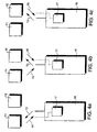
- the method according to the present invention for handover of a call in progress from a first radio link to a second radio link is generally illustrated in Figs. 4a, 4b and 4c.
- Fig. 4a shows in a very schematic manner a radio communication system comprising a remote radio communication unit 10, such as a telephone handset 4 or a (W)FAU 8 shown in Fig. 1, and two radio access units 11 and 12.
- Arrows 13 and 14 represent a first duplex radio link carrying a call in progress between the radio communication unit 10 and the first radio access unit 11.
- the radio communication unit 10 comprises a timing reference 17 which is synchronised or locked to the radio access unit 11, as indicated by a dashed line.
- the radio communication unit 10 is also in the range of the second radio access unit 12. It is assumed that the radio access units 11 and 12 do not operate time synchronous.
- the radio communication unit 10 has to perform an inter-cell handover of the call from the first radio access unit 11 to the second radio access unit 12. This because the user of the radio communication unit 10 is moving in the direction of the second radio access unit 12 or that the radio path between the radio communication unit 10 and first radio access unit 11 is suddenly blocked, for example.
- a suitable second duplex radio link 15, 16 is selected by the radio communication unit 10 and it starts to occupy this second radio link, however not before transmitting by the radio communication unit 10 at the first radio link 13, 14 is suspended.
- the radio communication unit 10 In order to establish the second radio link 15, 16 the radio communication unit 10 synchronizes its timing reference 17 to the second radio access unit, as indicated by the dashed line. If the second radio link 15, 16 is successfully established the call can be resumed and the first radio access unit 11 can cease its transmitting at the first radio link, either via a time out or upon receipt of message from the second radio access unit 12 indicating that the call has been taken over.
- the first radio access unit ceased its transmission at the first radio link 13, 14 whereas the radio communication unit 10 is now synchronised to the second radio access unit 12 and the second radio link 15, 16 which bears the call in progress.
- the first radio access unit not only may continue to transmit on the first radio link in order to prevent in a DCA/CDCS channel selection environment occupation thereof by another radio communication unit, such to have a fall back possibility in case the second radio link cannot be established, but preferably may continue to transmit the call itself.
- a simplex radio link is maintained. Note that a wide scan window can be used for receiving the first radio link which is now asynchronous to the radio communication unit 10.
- the method of handover of the present invention will not cause any interruption in the service provided, such that one may speak of a virtual seamless handover.
- a transmit suspension message may be forward by the remote radio communication unit 10 before transmitting at the first radio link is suspended.
- This message can be used for signalling purposes to the end users and may take the form of a spoken message, a special tone or tone sequence, a text displayed at a terminal display etc. In the case of a remote radio communication unit 10 still receiving at the first radio link, this message can also received back by the radio communication unit 10.
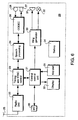
- Fig. 6 shows a simplified block diagram of a radio telephone set comprising frequency or clock control circuitry according to the present invention.
- the radio telephone set 20 has four essential building blocks, i.e. a central control and application logic unit 21, a radio unit 22, a timing and synchronisation control unit 23 and a speech processing unit 24.
- the radio unit 22 comprises an air interface 25 having an antenna system coupled to a transceiver unit comprising a transmitter/modulator and a receiver/demodulator (not shown).
- the timing and synchronisation control unit 23 receives data over the air interface 25 and the radio unit 22 from a base station 3 (Fig. 1), which data are processed in accordance with the system dock timing provided by the radio exchange 2 (Fig. 1). Signalling and synchronisation information are removed from the received data by the unit 23 and received speech data are fed to the speech processing unit 24.
- a codec 26 decodes the received digitised speech data into a form for making it audible to a user of the handset via a loudspeaker 27 connected to the codec 26.
- Speech produced by the user is received by a microphone 28 and encoded into a suitable digital format by the codec 26.
- This encoded speech data is fed to the speech processing unit 24 which, among others, takes care of encryption of the speech data.
- the timing and synchronisation control unit 23 adds suitable synchronisation and signalling information to the encrypted speech data.
- the radio unit 22 transmits this signalling and speech data via the air interface 25 for reception by a base station 3 (Fig. 1) of the communication system to which the telephone set 20 is operatively connected.
- the central control and application logic unit 21 comprises a microprocessor or microcontroller and memory means, and connects to the timing and synchronisation control unit 23.
- the central control unit 21 essentially controls the system data and the communication with the user of the radio telephone set 20 via a keypad means 29, display means 33 and ring generator means 30, all connected to the central control unit 21. Further, an external interface 35 connects to the central control unit 21 for external control and data processing purposes. Frame and time slot allocation and, in the case of a multi-carrier multi-time-slot technology such as DECT, also the various combinations of carrier frequencies and time-slots are controlled by the central control unit 21 and stored in the memory means.
- the ring generator means 30 connect to a buzzer 31 for producing a ringing or alerting sound at the arrival of a call.
- a visual alerting signal may be emitted by a lamp or Light Emitting Diode (LED) 32, connected as shown.
- the display means 33 such as an LCD device, are operatively connected to the central control unit 21 for displaying call information and other user and system data.
- a battery and powering unit 34 is included.
- the timing and synchronisation control unit 23 is controlled such to perform handover and roaming to synchronous as well asynchronous radio links.
- Fig. 7 shows a block diagram of a radio access unit 40 which operates in accordance with the DECT standard.
- the access unit 40 has a wired connection 41 to a radio exchange 2 shown in Fig. 1.
- Central control and application logic 42 detects incoming calls and controls outgoing calls and select suitable combinations of carrier and time slots in accordance with the DCA/CDCS algorithm. The different connections and time slots are merged via a multiplexer 43.
- the radio access unit 40 has a frame and slot synchronisation unit 44 which controls slot reception and transmission timing.
- the central control logic 42 also controls a Transmit/Receive (T/R) switch 45 and an antenna diversity switch 46, if antenna diversity is implemented.
- T/R Transmit/Receive
- the control logic first tries the other antenna before changing the radio communication channel.
- the radio interface of the access unit 40 consists of a receiver/demodulator 47 and a transmitter/modulator 48. Synchronisation and control information is stripped from received data by unit 49, whereas such information is added to the data to be transmitted by unit 50, connected as shown.
- the frame and slot synchronisation unit 44 is controlled such to support handover in accordance with the present invention.
- the present invention is generally illustrated with respect to a DECT radio telephone communication system, it is not restricted thereto.
- the present invention can be used with other communication devices, such as data communication equipment, as well as in other wireless multicell communication systems.
Landscapes
- Engineering & Computer Science (AREA)
- Computer Networks & Wireless Communication (AREA)
- Signal Processing (AREA)
- Mobile Radio Communication Systems (AREA)
Claims (20)
- Abtastungsverfahren zur Einleitung einer Anrufübergabe oder eines Roaming in einem Duplexfunkkommunikationssystem, das Funkzugangseinheiten (11, 12) und mindestens eine Fernfunkkommunikationseinheit (10) umfasst, wobei die Funkzugangseinheiten (11, 12) und die oder jede Fernfunkkommunikationseinheit (10) eingerichtet sind, um einen Anruf oder eine Funkverbindung zwischen einer Fernfunkkommunikationseinheit (10) und einer Funkzugangseinheit (11, 12) zu errichten, welche Funkverbindung ausgewählt ist aus einer Vielzahl von vorbestimmten Funkverbindungen, und um einen in einer ersten Funkverbindung (13, 14) zwischen einer Fernfunkkommunikationseinheit (10) und einer ersten Funkzugangseinheit (11) in Gang befindlichen Anruf auf eine zweite Funkverbindung (15, 16) zwischen der Fernfunkkommunikationseinheit (10) und einer zweiten Funkzugangseinheit (12) umzuschalten, dadurch gekennzeichnet, dass wenn jede oder Gruppen von Funkzugangseinheiten (11, 12) auf gegenseitig zeitlich asynchrone Weise betrieben werden, um eine asynchrone Funkumgebung zu bilden, und die Fernfunkkommunikationseinheit (10) mit einer ersten Funkzugangseinheit (11) synchronisiert ist, das Verfahren die folgenden von der Fernfunkkommunikationseinheit (10) durchgeführten Schritte umfasst:a) Abtasten der Funkumgebung nach Funkzugangseinheiten, welche auf zeitlich synchrone Weise mit der ersten Funkzugangseinheit (11) arbeiten, unter Verwendung eines Abtastfensters, das eine Breite und/oder zeitliche Position hat, sodass es im wesentlichen Synchronisationsdaten und Steuerungsdaten, die während einer vorbestimmten Zeitperiode in einer Funkverbindungsbetriebszeit synchron mit der ersten Funkverbindung (13, 14) ausgetauscht werden, holt,b) Abtasten der Funkumgebung nach Funkzugangseinheiten, welche auf zeitlich asynchrone Weise mit der ersten Funkzugangseinheit (11) arbeiten, unter Verwendung eines Abtastfensters, dass eine solche Breite und zeitliche Position hat, das Synchronisationsdaten und Steuerungsdaten, welche im wesentlichen außerhalb der vorbestimmten Zeitperiode ausgetauscht werden, geholt werden,c) Unterhalten einer Liste von synchronen und asynchronen Funkverbindungen, die für die Übergabe zur Verfügung stehen, undd) Auswerten der Liste auf der Grundlage von vorbestimmten Funkverbindungskriterien, um so zu bestimmen, ob eine Übergabe oder ein Roaming eingeleitet werden muss.
- Verfahren nach Anspruch 1, wobei bei Schritt a) die Fernkommunikationseinheit (10) ihre Zeitreferenz mit den geholten Synchronisationsdaten synchronisiert.
- Verfahren nach Anspruch 1 oder 2, wobei bei Schritt b) das Abtastfenster eine solche Breite und zeitliche Position hat, dass es die vorbestimmte Zeitperiode enthält, und wobei synchrone Funkverbindungen und asynchrone Funkverbindungen auf der Grundlage der Zeitdifferenz zwischen dem Empfang der Synchronisationsdaten und der vorbestimmten Zeitperiode unterschieden werden.
- Verfahren nach Anspruch 3, wobei die Zeitdifferenz von der Funkkommunikationseinheit (10) verwendet wird, um ihre Zeitreferenz einzustellen.
- Verfahren nach Anspruch 1, 2, 3 oder 4, wobei der Schritt a) und Schritt b) mit unterschiedlichen Raten durchgeführt werden.
- Verfahren nach Anspruch 5, wobei der Schritt a) bei einer höheren Rate als Schritt b) durchgeführt wird, wenn eine Zahl von synchronen Funkverbindungen, die für eine Übergabe adäquat sind, erfasst wird, wobei die Zahl und die Rate adaptiv eingestellt werden können, abhängig von vorbestimmten Funkverbindungskriterien.
- Verfahren nach einem der Ansprüche 1 bis 6, wobei bei Schritt a) und Schritt b) die Zahl der abzutastenden Funkverbindungen begrenzt ist, wenn eine Zahl von für eine Übergabe adäquate Funkverbindungen erfasst wird, wobei die Zahl adaptiv eingestellt werden kann, abhängig von vorbestimmten Funkverbindungskriterien.
- Verfahren nach Anspruch 6 oder 7, wobei das Funkkommunikationssystem in Übereinstimmung mit dem Standard für Digitale Europäische Schnurlostelekommunikation (DECT) arbeitet, und wobei die vorbestimmten Funkverbindungskriterien gebildet werden durch eines oder eine Kombination der folgenden Kriterien: HF-Signalpegel (RSSI), Fehler der Burstsynchronisation (SYNC), Fehler des Systeminformations-Feldtestworts (A CRC), Fehler des Datenfeld-Testworts (X CRC).
- Verfahren nach einem der vorangehenden Ansprüche, ferner umfassend die Schritte:e) Aussetzen der Übertragung durch die Fernfunkkommunikationseinheit (10) in der ersten Funkverbindung (13, 14) während das Übertragen durch die erste Funkzugangseinheit (11) in der ersten Funkverbindung (14) aufrecht erhalten wird,f) Herstellen der zweiten Funkverbindung (15, 16),g) Wiederaufnahme des Anrufs in der zweiten Funkverbindung (15, 16), undh) Freigabe der ersten Funkverbindung (14) durch die erste Funkzugangseinheit (11).
- Verfahren nach Anspruch 9, wobei die ersten und zweiten Funkzugangseinheiten (11, 12) auf gegenseitig zeitlich asynchrone Weise betrieben werden, und wobei die ersten und zweiten Funkzugangseinheiten (11, 12) einen Teil von ersten und zweiten zeitlich unabhängig betriebenen Funkkommunikationsnetzen sein können.
- Verfahren nach Anspruch 9 oder 10, wobei während der Schritte e) und f) die erste Funkzugangseinheit (11) die Übertragung des Anrufs in der ersten Funkverbindung (14) aufrecht erhält, und die Fernfunkkommunikationseinheit (10) das Empfangen des Anrufs in der ersten Funkverbindung (14) aufrecht erhält.
- Verfahren nach Anspruch 9, 10 oder 11, wobei zu Beginn der Übergabe die Fernkommunikationseinheit (10) eine Übertragungsaussetzungsmitteilung an die erste Funkzugangseinheit (11) weiterleitet.
- Verfahren nach Anspruch 12, wobei nach Empfang der Übertragungsaussetzungsmitteilung durch die erste Funkzugangseinheit (11), eine Signalisierungsmitteilung ausgetauscht wird, zum Zwecke der Angabe, dass der Anruf einer Übergabe unterliegt, welche Mitteilung endgeräteseitig die Form eines Sprachsignals, eines Audiotonsignals oder eines visuellen Anzeigesignals annehmen kann, ohne hierauf beschränkt zu sein, und wobei die Signalisierungsmitteilung freigegeben wird, wenn der Anruf wieder aufgenommen wird.
- Verfahren nach Anspruch 9, 10, 11, 12 oder 13, wobei wenn der Anruf in der zweiten Funkverbindung (15, 16) wieder aufgenommen wird, die erste Funkverbindung (14) freigegeben wird nach einer vorbestimmten Zeitperiode nach der Aussetzung der Übertragung durch die Fernkommunikationseinheit (10).
- Verfahren nach Anspruch 9, 10, 11, 12, 13 oder 14, wobei wenn der Anruf in der zweiten Funkverbindung (15, 16) wieder aufgenommen wird, eine Freigabemitteilung an die erste Funkzugangseinheit (11) über ihr entsprechendes Funkkommunikationsnetz weitergeleitet wird, um die erste Funkverbindung (14) freizugeben.
- Verfahren nach Anspruch 9, 10, 11, 12, oder 13, wobei wenn die zweite Funkverbindung (15, 16) nicht hergestellt werden kann, der Anruf in der ersten Funkverbindung (13, 14) wieder aufgenommen wird.
- Verfahren nach Anspruch 16, wobei wenn der Anruf in der ersten Funkverbindung (13, 14) nicht wieder aufgenommen werden kann, eine dritte Funkverbindung zwischen der Funkkommunikationseinheit (10) und der ersten Funkzugangseinheit (11) errichtet wird, und der Anruf in der dritten Funkverbindung wieder aufgenommen wird.
- Verfahren nach einem der Ansprüche 9 bis 17, wobei der Anruf unter Aufrechterhaltung von für die erste Funkverbindung (13, 14) besonderen Anrufsteuerungsmerkmalen wieder aufgenommen wird.
- Fernkommunikationseinheit (20), wie zum Beispiel ein Funktelefon zur Verwendung in einem Duplexfunkkommunikationssystem, das Funkzugangseinheiten (40) und mindestens eine Fernkommunikationseinheit (20) umfasst, insbesondere ein schnurloses Funkkommunikationssystem, wobei die Fernkommunikationseinheit (20) Steuerungsmittel (23) umfasst, die ausgebildet sind, um gemäß jedem der Schritte des Verfahrens nach einem der vorangehenden Ansprüche zu arbeiten.
- Funkzugangseinheit (40), wie zum Beispiel eine Funkbasisstation zur Verwendung in einem Duplexfunkkommunikationssystem, das Funkzugangseinheiten (40) und mindestens eine Fernkommunikationseinheit (20) enthält, insbesondere ein schnurloses Funkkommunikationssystem, wobei die Funkzugangseinheit (40) Steuerungsmittel (44) umfasst, die ausgebildet sind, um gemäß jedem der Schritte des Verfahrens nach einem der Ansprüche 1 bis 18 zu arbeiten.
Priority Applications (1)
| Application Number | Priority Date | Filing Date | Title |
|---|---|---|---|
| EP96934731A EP0856232B1 (de) | 1995-10-17 | 1996-10-16 | Verfahren zur verbindungsübergabe und netzwerkwechsel in einer funkübertragungsumgebung |
Applications Claiming Priority (4)
| Application Number | Priority Date | Filing Date | Title |
|---|---|---|---|
| EP95202806 | 1995-10-17 | ||
| EP95202806 | 1995-10-17 | ||
| EP96934731A EP0856232B1 (de) | 1995-10-17 | 1996-10-16 | Verfahren zur verbindungsübergabe und netzwerkwechsel in einer funkübertragungsumgebung |
| PCT/EP1996/004519 WO1997015160A1 (en) | 1995-10-17 | 1996-10-16 | A method for performing handover and roaming in a radio communication environment |
Publications (2)
| Publication Number | Publication Date |
|---|---|
| EP0856232A1 EP0856232A1 (de) | 1998-08-05 |
| EP0856232B1 true EP0856232B1 (de) | 2003-02-19 |
Family
ID=8220727
Family Applications (1)
| Application Number | Title | Priority Date | Filing Date |
|---|---|---|---|
| EP96934731A Expired - Lifetime EP0856232B1 (de) | 1995-10-17 | 1996-10-16 | Verfahren zur verbindungsübergabe und netzwerkwechsel in einer funkübertragungsumgebung |
Country Status (9)
| Country | Link |
|---|---|
| US (1) | US6236860B1 (de) |
| EP (1) | EP0856232B1 (de) |
| JP (1) | JP3834677B2 (de) |
| KR (1) | KR100351256B1 (de) |
| CN (1) | CN1110980C (de) |
| AU (1) | AU7295296A (de) |
| CA (1) | CA2232693C (de) |
| DE (1) | DE69626294T2 (de) |
| WO (1) | WO1997015160A1 (de) |
Families Citing this family (57)
| Publication number | Priority date | Publication date | Assignee | Title |
|---|---|---|---|---|
| US6418324B1 (en) * | 1995-06-01 | 2002-07-09 | Padcom, Incorporated | Apparatus and method for transparent wireless communication between a remote device and host system |
| SG72725A1 (en) * | 1997-01-03 | 2000-05-23 | Motorola Inc | Asynchronous channel frequency scanning |
| JP3080901B2 (ja) * | 1997-05-15 | 2000-08-28 | 日本電気通信システム株式会社 | 多方向多重通信システムにおけるisdnサービス方法 |
| DE19738340C2 (de) * | 1997-09-02 | 2001-03-15 | Siemens Ag | Roaming von Mobilteilen in zumindest teilweise asynchronen drahtlosen Telekommunikationsnetzen, insbesondere DECT-Netzen |
| US6101175A (en) * | 1997-10-31 | 2000-08-08 | Motorola, Inc. | Method and apparatus for handoff within a communication system |
| EP0944272A1 (de) * | 1998-03-18 | 1999-09-22 | Alcatel | Telekommunikationsanlage mit mehreren Funkbasisstationen |
| JP3323809B2 (ja) * | 1998-06-19 | 2002-09-09 | 松下電器産業株式会社 | 時分割多重無線通信方式の受信電界強度測定装置 |
| DE19843476C2 (de) * | 1998-09-22 | 2001-12-20 | Siemens Ag | Verfahren zur Funkversorgung eines Mobil-Terminals eines Mobilfunknetzes |
| US6470179B1 (en) | 1998-12-30 | 2002-10-22 | At&T Corp. | Automatic service selection feature for neighborhood residential cordless service |
| US6445911B1 (en) | 1998-12-30 | 2002-09-03 | At&T Corp | Method and apparatus for providing neighborhood cordless services |
| US7181207B1 (en) | 1998-12-30 | 2007-02-20 | At&T Corp. | Method and apparatus for over-the-air activation of neighborhood cordless-type services |
| US6546253B1 (en) | 1998-12-30 | 2003-04-08 | At&T Corp. | Neighborhood cordless service call handoff |
| US6594488B1 (en) | 1998-12-30 | 2003-07-15 | At&T Corp. | Method and apparatus for over-the-air activation of neighborhood cordless-type services |
| US7257404B1 (en) | 1998-12-30 | 2007-08-14 | At&T Corp. | Neighborhood cordless service call handoff |
| DE69907748T2 (de) * | 1999-01-25 | 2004-03-18 | Nokia Corp. | Kooperation unterschiedlicher funknetzwerke |
| HK1043012B (zh) | 1999-02-26 | 2005-10-28 | 高通股份有限公司 | 用於异步码分多址基站和同步码分多址基站之间越区切换的方法 |
| US6873647B1 (en) * | 1999-02-26 | 2005-03-29 | Qualcomm Incorporated | Method and system for reducing synchronization time in a CDMA wireless communication system |
| USRE47895E1 (en) | 1999-03-08 | 2020-03-03 | Ipcom Gmbh & Co. Kg | Method of allocating access rights to a telecommunications channel to subscriber stations of a telecommunications network and subscriber station |
| DE19916991A1 (de) * | 1999-04-15 | 2000-10-19 | Alcatel Sa | Telekommunikations-System mit mehreren Funkzellen |
| US6445917B1 (en) * | 1999-05-19 | 2002-09-03 | Telefonaktiebolaget Lm Ericsson (Publ) | Mobile station measurements with event-based reporting |
| GB2352586B (en) * | 1999-06-07 | 2004-03-10 | Nec Corp | Handover between mobile networks |
| US6477373B1 (en) * | 1999-08-10 | 2002-11-05 | Research Foundation Of State University Of New York | Method and apparatus to maintain connectivity for mobile terminals in wireless and cellular communications systems |
| EP1081977A1 (de) * | 1999-08-31 | 2001-03-07 | TELEFONAKTIEBOLAGET L M ERICSSON (publ) | Teilnehmergerät, Netzsteuerungsmittel und Verfahren zur Auslösung von Interfrequenz-Messungen in einem mobilen Kommunikationssystem |
| US7171199B1 (en) * | 1999-09-10 | 2007-01-30 | Lucent Technologies Inc. | Method and system for directing a data message in a wireless communications network including multiple wireless systems |
| KR100680072B1 (ko) * | 1999-09-14 | 2007-02-09 | 유티스타콤코리아 유한회사 | 비동기 이동통신 시스템에서 호 처리 및 핸드오프 처리 방법 |
| US6625467B2 (en) | 2000-07-13 | 2003-09-23 | Qualcomm, Incorporated | Method and apparatus for performing idle mode reacquisition and handoff in an asynchronous communication system |
| ATE261645T1 (de) * | 2000-10-18 | 2004-03-15 | Lg Electronics Inc | Verfahren zur steuerung des weiterreichens in einem schema für synchrone aufwärtsübertragung |
| KR100401701B1 (ko) * | 2000-11-13 | 2003-10-17 | 에스케이 텔레콤주식회사 | 무선 데이터 사용중의 음성 호 착신 통보 방법 및 이를처리하는 방법 |
| JP2003051857A (ja) * | 2001-08-06 | 2003-02-21 | Nec Corp | データ通信システム、データ通信端末及びそれに用いるデータ通信方法並びにそのプログラム |
| US7082304B2 (en) * | 2002-06-05 | 2006-07-25 | Mitsubishi Denki Kabushiki Kaisha | Radio communication system, base station device, mobile terminal device, and radio link switching method |
| KR100459432B1 (ko) * | 2002-08-21 | 2004-12-03 | 엘지전자 주식회사 | 이동통신 시스템의 핸드오버 처리방법 |
| DE10261201A1 (de) * | 2002-12-20 | 2004-07-15 | Philips Semiconductors Dresden Ag | Verfahren zur Herstellung einer Verbindung zwischen einer Mobilstation und einem Kommunikationsnetzwerk |
| US7414992B2 (en) * | 2003-06-30 | 2008-08-19 | Motorola, Inc. | Method and apparatus for providing a hand-in to a wireless local area network |
| US7853215B2 (en) * | 2003-10-10 | 2010-12-14 | Motorola, Inc. | Communication circuit and method for selecting a reference link |
| US7387939B2 (en) * | 2004-07-19 | 2008-06-17 | Micron Technology, Inc. | Methods of forming semiconductor structures and capacitor devices |
| US20060079218A1 (en) * | 2004-10-13 | 2006-04-13 | Tylu Wireless Technology, Inc. | Filtered wireless communications |
| KR101038628B1 (ko) * | 2004-10-28 | 2011-06-03 | 에스케이 텔레콤주식회사 | 비동기 이동통신 시스템으로부터 와이브로 시스템으로의서비스 전환 방법 |
| US20060223542A1 (en) * | 2005-03-31 | 2006-10-05 | Comroe Richard A | Filtered wireless communications |
| CN100450284C (zh) * | 2005-06-01 | 2009-01-07 | 华为技术有限公司 | 无线通信系统中实现终端切换的方法 |
| WO2007006217A1 (en) * | 2005-07-08 | 2007-01-18 | Huawei Technologies Co., Ltd. | Method of inter-system handover |
| KR100703802B1 (ko) * | 2005-10-20 | 2007-04-06 | 삼성전자주식회사 | 무선 네트워크 상에서 핸드오버 방법 및 장치 |
| CN101137161B (zh) * | 2006-11-27 | 2010-09-01 | 中兴通讯股份有限公司 | 上电链路建立方法及系统 |
| KR100784324B1 (ko) * | 2006-11-28 | 2007-12-13 | 삼성전자주식회사 | 이동통신 단말기에서 대기 전류 절약 장치 및 방법 |
| CN101335981B (zh) * | 2007-06-26 | 2011-09-28 | 鼎桥通信技术有限公司 | 一种三载波td-scdma系统的载波分配方法 |
| US20100195553A1 (en) * | 2008-03-18 | 2010-08-05 | Myers Theodore J | Controlling power in a spread spectrum system |
| US8477830B2 (en) | 2008-03-18 | 2013-07-02 | On-Ramp Wireless, Inc. | Light monitoring system using a random phase multiple access system |
| US8958460B2 (en) * | 2008-03-18 | 2015-02-17 | On-Ramp Wireless, Inc. | Forward error correction media access control system |
| US8520721B2 (en) | 2008-03-18 | 2013-08-27 | On-Ramp Wireless, Inc. | RSSI measurement mechanism in the presence of pulsed jammers |
| US8363699B2 (en) | 2009-03-20 | 2013-01-29 | On-Ramp Wireless, Inc. | Random timing offset determination |
| US8477703B2 (en) * | 2009-06-24 | 2013-07-02 | Texas Instruments Incorporated | Channel utilization improvement in coexisting wireless networks |
| US8774109B2 (en) | 2010-06-17 | 2014-07-08 | Kathrein-Werke Kg | Mobile communications network with distributed processing resources |
| US8649354B2 (en) * | 2010-06-17 | 2014-02-11 | Kathrein-Werke Kg | Handover in mobile communications networks |
| BR112017012744A2 (pt) * | 2014-12-17 | 2018-03-13 | Ericsson Telefon Ab L M | atribuição flexível de funções de rede para acesso via rádio |
| WO2016148617A1 (en) | 2015-03-18 | 2016-09-22 | Telefonaktiebolaget Lm Ericsson (Publ) | Apparatus and methods for paging |
| WO2016175690A1 (en) | 2015-04-30 | 2016-11-03 | Telefonaktiebolaget Lm Ericsson (Publ) | Relaxed measurement reporting with control plane dual connectivity |
| CN114040457B (zh) | 2017-01-05 | 2025-01-10 | 日本电气株式会社 | 无线接入网节点、无线终端及其方法和计算机可读介质 |
| WO2019139691A1 (en) * | 2018-01-10 | 2019-07-18 | Kyocera Corporation | Transmission of wake-up signal to mobile devices at alternate carrier frequency |
Family Cites Families (16)
| Publication number | Priority date | Publication date | Assignee | Title |
|---|---|---|---|---|
| JPS55109042A (en) * | 1979-02-14 | 1980-08-21 | Nec Corp | Selective individual calling system |
| SE430013B (sv) | 1981-12-21 | 1983-10-10 | Ericsson Telefon Ab L M | Forfarande och anleggning for overforing av telefonsamtal till en berbar, tradlos telefonapparat |
| US4485486A (en) * | 1982-08-03 | 1984-11-27 | Motorola, Inc. | Method and apparatus for assigning duplex radio channels and scanning duplex radio channels assigned to mobile and portable radio telephones in a cellular radiotelephone communications system |
| SE448199B (sv) | 1985-05-09 | 1987-01-26 | Ericsson Telefon Ab L M | Anleggning med flera berbara, snorlosa telefonapparater |
| JPS62225096A (ja) * | 1986-03-26 | 1987-10-03 | Nec Corp | 無線電話方式 |
| CA1250900A (en) * | 1986-11-18 | 1989-03-07 | Northern Telecom Limited | Private cellular system |
| US4866710A (en) * | 1988-02-22 | 1989-09-12 | Motorola, Inc. | Reuse groups for scan monitoring in digital cellular systems |
| CA2030641C (en) | 1989-11-24 | 1994-05-31 | Yasushi Yamao | Radio communication equipment for a mobile station and traffic channel hand-off method using the same |
| JPH04170825A (ja) * | 1990-11-05 | 1992-06-18 | Toshiba Corp | 無線通信方式 |
| US5214790A (en) | 1991-03-11 | 1993-05-25 | Motorola, Inc. | Enhanced talkgroup scan algorithm |
| CH682867A5 (de) | 1991-09-24 | 1993-11-30 | Ascom Tech Ag | Verfahren zum Durchführen eines Handovers. |
| US5260988A (en) * | 1992-02-06 | 1993-11-09 | Motorola, Inc. | Apparatus and method for alternative radiotelephone system selection |
| WO1994000946A1 (en) | 1992-06-23 | 1994-01-06 | Motorola Inc. | Dual system cellular cordless radiotelephone apparatus with sub-data channel timing monitor |
| JP2590692B2 (ja) * | 1993-07-14 | 1997-03-12 | 日本電気株式会社 | 移動通信における通話中チャネル切替方法およびシステム |
| JPH07170577A (ja) * | 1993-12-14 | 1995-07-04 | Uniden Corp | コードレス電話機 |
| US5488649A (en) * | 1994-05-06 | 1996-01-30 | Motorola, Inc. | Method for validating a communication link |
-
1996
- 1996-10-16 EP EP96934731A patent/EP0856232B1/de not_active Expired - Lifetime
- 1996-10-16 CA CA002232693A patent/CA2232693C/en not_active Expired - Lifetime
- 1996-10-16 US US09/051,661 patent/US6236860B1/en not_active Expired - Lifetime
- 1996-10-16 DE DE69626294T patent/DE69626294T2/de not_active Expired - Lifetime
- 1996-10-16 KR KR10-1998-0702812A patent/KR100351256B1/ko not_active Expired - Lifetime
- 1996-10-16 WO PCT/EP1996/004519 patent/WO1997015160A1/en not_active Ceased
- 1996-10-16 JP JP51553197A patent/JP3834677B2/ja not_active Expired - Lifetime
- 1996-10-16 CN CN96197709A patent/CN1110980C/zh not_active Expired - Lifetime
- 1996-10-16 AU AU72952/96A patent/AU7295296A/en not_active Abandoned
Also Published As
| Publication number | Publication date |
|---|---|
| JP3834677B2 (ja) | 2006-10-18 |
| CN1110980C (zh) | 2003-06-04 |
| DE69626294D1 (de) | 2003-03-27 |
| HK1017218A1 (en) | 1999-11-12 |
| AU7295296A (en) | 1997-05-07 |
| CA2232693C (en) | 2005-02-08 |
| EP0856232A1 (de) | 1998-08-05 |
| WO1997015160A1 (en) | 1997-04-24 |
| KR100351256B1 (ko) | 2003-01-08 |
| CA2232693A1 (en) | 1997-04-24 |
| US6236860B1 (en) | 2001-05-22 |
| DE69626294T2 (de) | 2003-11-13 |
| KR19990064316A (ko) | 1999-07-26 |
| JPH11513852A (ja) | 1999-11-24 |
| CN1200228A (zh) | 1998-11-25 |
Similar Documents
| Publication | Publication Date | Title |
|---|---|---|
| US6236860B1 (en) | Method for performing handover and roaming in a radio communication environment | |
| US7092710B1 (en) | Method of and equipment for performing radio communication in a plurality of radio communication environments | |
| RU2148894C1 (ru) | Мобильный радиоприемный аппарат для сотовых радио-телекоммуникационных систем (варианты) | |
| KR100378320B1 (ko) | 광역 셀룰러망 및 개인용 무선통신망으로부터 입중계 호출을 동시에 수신하는 방법 및 이동단말기 | |
| US6507740B2 (en) | Adaptive threshold of handoff in mobile telecommunication systems | |
| EP2315475B1 (de) | Drahtlose private nebenstellenanlage und kommunikation zwischen mobilen einheiten und basisstationen | |
| Fluhr et al. | Advanced mobile phone service: Control architecture | |
| EP0961512B1 (de) | Verfahren zum weiterreichen in einer Funkkommunikationsumgebung | |
| WO1998009458A1 (en) | Methods and systems for mobile terminal assisted handover in a private radio communications network | |
| US6252860B1 (en) | Method and system for improving the degree utilization of telecommunications channels in locally concentrated, asynchronous wireless telecommunications systems | |
| AU2256000A (en) | A telecommunications system with a plurality of radio cells | |
| CA2302330C (en) | Roaming of mobile parts in at least partially asynchronous wireless telecommunications networks, especially dect networks | |
| EP0930794B1 (de) | Ubertragung von Kanalinformation in einem Funkübertragungssystem | |
| EP1410670B1 (de) | Verfahren und vorrichtung zum auswählen einer funkzugriffseinheit in einem funkkommunikationssystem | |
| JPH10271553A (ja) | 無線電話システム | |
| HK1017218B (en) | A method for performing handover and roaming in a radio communication environment | |
| MXPA00009512A (en) | Method and arrangement for determining the presence of a mobile station in a determined area | |
| JPH0358529A (ja) | 移動体通信システム |
Legal Events
| Date | Code | Title | Description |
|---|---|---|---|
| PUAI | Public reference made under article 153(3) epc to a published international application that has entered the european phase |
Free format text: ORIGINAL CODE: 0009012 |
|
| 17P | Request for examination filed |
Effective date: 19980211 |
|
| AK | Designated contracting states |
Kind code of ref document: A1 Designated state(s): DE ES FI FR GB IT NL SE |
|
| GRAH | Despatch of communication of intention to grant a patent |
Free format text: ORIGINAL CODE: EPIDOS IGRA |
|
| GRAH | Despatch of communication of intention to grant a patent |
Free format text: ORIGINAL CODE: EPIDOS IGRA |
|
| GRAA | (expected) grant |
Free format text: ORIGINAL CODE: 0009210 |
|
| AK | Designated contracting states |
Designated state(s): DE ES FI FR GB IT NL SE |
|
| PG25 | Lapsed in a contracting state [announced via postgrant information from national office to epo] |
Ref country code: NL Free format text: LAPSE BECAUSE OF FAILURE TO SUBMIT A TRANSLATION OF THE DESCRIPTION OR TO PAY THE FEE WITHIN THE PRESCRIBED TIME-LIMIT Effective date: 20030219 Ref country code: IT Free format text: LAPSE BECAUSE OF FAILURE TO SUBMIT A TRANSLATION OF THE DESCRIPTION OR TO PAY THE FEE WITHIN THE PRESCRIBED TIME-LIMIT;WARNING: LAPSES OF ITALIAN PATENTS WITH EFFECTIVE DATE BEFORE 2007 MAY HAVE OCCURRED AT ANY TIME BEFORE 2007. THE CORRECT EFFECTIVE DATE MAY BE DIFFERENT FROM THE ONE RECORDED. Effective date: 20030219 Ref country code: FR Free format text: LAPSE BECAUSE OF NON-PAYMENT OF DUE FEES Effective date: 20030219 Ref country code: FI Free format text: LAPSE BECAUSE OF FAILURE TO SUBMIT A TRANSLATION OF THE DESCRIPTION OR TO PAY THE FEE WITHIN THE PRESCRIBED TIME-LIMIT Effective date: 20030219 |
|
| REG | Reference to a national code |
Ref country code: GB Ref legal event code: FG4D |
|
| REF | Corresponds to: |
Ref document number: 69626294 Country of ref document: DE Date of ref document: 20030327 Kind code of ref document: P |
|
| PG25 | Lapsed in a contracting state [announced via postgrant information from national office to epo] |
Ref country code: SE Free format text: LAPSE BECAUSE OF FAILURE TO SUBMIT A TRANSLATION OF THE DESCRIPTION OR TO PAY THE FEE WITHIN THE PRESCRIBED TIME-LIMIT Effective date: 20030519 |
|
| NLV1 | Nl: lapsed or annulled due to failure to fulfill the requirements of art. 29p and 29m of the patents act | ||
| PG25 | Lapsed in a contracting state [announced via postgrant information from national office to epo] |
Ref country code: ES Free format text: LAPSE BECAUSE OF FAILURE TO SUBMIT A TRANSLATION OF THE DESCRIPTION OR TO PAY THE FEE WITHIN THE PRESCRIBED TIME-LIMIT Effective date: 20030828 |
|
| PLBE | No opposition filed within time limit |
Free format text: ORIGINAL CODE: 0009261 |
|
| STAA | Information on the status of an ep patent application or granted ep patent |
Free format text: STATUS: NO OPPOSITION FILED WITHIN TIME LIMIT |
|
| EN | Fr: translation not filed | ||
| 26N | No opposition filed |
Effective date: 20031120 |
|
| PGFP | Annual fee paid to national office [announced via postgrant information from national office to epo] |
Ref country code: DE Payment date: 20151028 Year of fee payment: 20 Ref country code: GB Payment date: 20151027 Year of fee payment: 20 |
|
| REG | Reference to a national code |
Ref country code: DE Ref legal event code: R071 Ref document number: 69626294 Country of ref document: DE |
|
| REG | Reference to a national code |
Ref country code: GB Ref legal event code: PE20 Expiry date: 20161015 |
|
| PG25 | Lapsed in a contracting state [announced via postgrant information from national office to epo] |
Ref country code: GB Free format text: LAPSE BECAUSE OF EXPIRATION OF PROTECTION Effective date: 20161015 |