EP0856248B1 - Dispositif de contrôle du liage des balles dans une presse agricole - Google Patents
Dispositif de contrôle du liage des balles dans une presse agricole Download PDFInfo
- Publication number
- EP0856248B1 EP0856248B1 EP98200140A EP98200140A EP0856248B1 EP 0856248 B1 EP0856248 B1 EP 0856248B1 EP 98200140 A EP98200140 A EP 98200140A EP 98200140 A EP98200140 A EP 98200140A EP 0856248 B1 EP0856248 B1 EP 0856248B1
- Authority
- EP
- European Patent Office
- Prior art keywords
- strands
- mistie
- sensing
- packages
- movement
- Prior art date
- Legal status (The legal status is an assumption and is not a legal conclusion. Google has not performed a legal analysis and makes no representation as to the accuracy of the status listed.)
- Expired - Lifetime
Links
- 239000000463 material Substances 0.000 claims description 48
- 238000000034 method Methods 0.000 claims description 16
- 238000012544 monitoring process Methods 0.000 claims description 10
- 230000002950 deficient Effects 0.000 claims description 4
- 238000006073 displacement reaction Methods 0.000 claims 2
- 230000007246 mechanism Effects 0.000 description 33
- 238000001514 detection method Methods 0.000 description 7
- 230000001351 cycling effect Effects 0.000 description 4
- 238000009825 accumulation Methods 0.000 description 2
- 230000008878 coupling Effects 0.000 description 2
- 238000010168 coupling process Methods 0.000 description 2
- 238000005859 coupling reaction Methods 0.000 description 2
- 230000004044 response Effects 0.000 description 2
- 241001589086 Bellapiscis medius Species 0.000 description 1
- 230000015572 biosynthetic process Effects 0.000 description 1
- 230000001419 dependent effect Effects 0.000 description 1
- 238000010586 diagram Methods 0.000 description 1
- 238000007599 discharging Methods 0.000 description 1
- 230000000694 effects Effects 0.000 description 1
- 239000004463 hay Substances 0.000 description 1
- 238000003780 insertion Methods 0.000 description 1
- 230000037431 insertion Effects 0.000 description 1
- 230000001788 irregular Effects 0.000 description 1
- 239000004973 liquid crystal related substance Substances 0.000 description 1
- 238000005259 measurement Methods 0.000 description 1
- 230000003287 optical effect Effects 0.000 description 1
- 230000000737 periodic effect Effects 0.000 description 1
- 239000004460 silage Substances 0.000 description 1
- 239000010902 straw Substances 0.000 description 1
- 230000000007 visual effect Effects 0.000 description 1
Images


Classifications
-
- A—HUMAN NECESSITIES
- A01—AGRICULTURE; FORESTRY; ANIMAL HUSBANDRY; HUNTING; TRAPPING; FISHING
- A01F—PROCESSING OF HARVESTED PRODUCE; HAY OR STRAW PRESSES; DEVICES FOR STORING AGRICULTURAL OR HORTICULTURAL PRODUCE
- A01F15/00—Baling presses for straw, hay or the like
- A01F15/08—Details
- A01F15/14—Tying devices specially adapted for baling presses
- A01F15/148—Monitoring the tying, e.g. mistie detectors
Definitions
- the present invention relates generally to an apparatus and a method for detecting mistie conditions in an agricultural baler, and more particularly to an apparatus and a method involving sensing a state of the strands of binding material which are supplied to the baling chamber.
- balers such as the large rectangular balers are designed for making bales of a multitude of crops in a wide range of circumstances.
- the operator tends to maximize the density of the bales thereby increasing the tension in the strands of binding material which are tied around the crop material in the baling chamber.
- the forces on the tying mechanism increase accordingly and the system becomes more prone to failure, e.g. because one of the strands slips out of the knotters, or because the strand itself breaks.
- the adjustment of the various components of the tying mechanism becomes vary critical and misties cannot always be precluded.
- the mistie detection system involves monitoring the closed loop after the knotter has cycled. When no closed loop is sensed a mistie signal is generated. Such system rapidly indicates a failure of a knot in a completed bale, but will not react to a breakage of a strand which still has to tied around the next bale. Hence the operator misses the opportunity to reinstall the twine before the next knotting cycle, which would have constituted the most efficient remedy. Now he has to wrap a complete new loop around the completed bale.
- Twine breakage may be detected by a mistie detection system according to DD 208,748, but herein the switch on the trip arm prevents that any mistie signals are passed on to the operator before the new bale is almost completed. A failure of the knotting system will be indicated only at a very late stage.
- a mistie detector for an agricultural baler, which comprises:
- Said mistie detector comprising means for sensing a state of said strands and is characterized in that said:
- a method for detecting a defective strand condition in an agricultural baler which comprises:
- Said method is characterized in that it comprises the steps of, in any convenient order:
- the actual movement of the twines is dependent on the properties of the crop material (hay, straw, silage, ...) and the machine settings (e.g. density control).
- the mistie detector compares the relative values of strand movement instead of absolute values, no system parameters have to be adapted when any of the conditions above is changed.
- Sensors may be provided for monitoring the transverse motion of the strands, e.g. by vibration sensors. Otherwise sensors can be used for monitoring their longitudinal motion. In this case one may direct sensors to the guide wheels along which binding material is supplied to the baling chamber. Their signals enable establishment of length values for each strand. The length values may be compared to a threshold value, which can be set equal to a predetermined percentage of the mean value of all length values.
- Such means may include a sensor sensing the operation of a particular mechanical component, such as the loading means. When the component has stopped cycling the sensor signals are disregarded until the next cycle.
- FIG. 1 shows an agricultural baler 10 which is equipped with a forwardly extending tongue 12 provided with hitch means (not shown) at its front end for coupling the baler 10 to a towing tractor.
- a pick-up assembly 14 lifts windrowed crop material off the field as the baler 10 is travelled thereover and delivers such material into the front end of a rearwardly and upwardly curved, charge-forming feeder duct 16.
- the duct 16 communicates at its upper end with an overhead, fore-and-aft extending baling chamber 18 into which crop charges are loaded by a cyclically operating stuffer mechanism 20.
- a continuously operating packer mechanism 22 at the lower front end of the feeder duct 16 continuously feeds and packs material into the duct 16 as to cause charges of the crop material to take on and assume the internal configuration of the duct 16 prior to periodic engagement by the stuffer 20 and insertion up into the baling chamber 18.
- the feeder duct 16 may be equipped with means for establishing whether a complete charge has been formed therein and operating the stuffer 20 in response thereto. Each action of the stuffer 20 introduces a "charge” or "flake” of crop material from the duct 16 into the chamber 18.
- a plunger 24 reciprocates in a fore-and-aft direction within the baling chamber 18 to push each new charge introduced into the baling chamber 18 rearwardly and form them into a package of crop material therein, which is pushed by the plunger 24 toward a rearmost discharge aperture 26 of the chamber.
- Each package is securely bound in its final compacted form by a tying mechanism 30 before leaving the confines of the baler 10.
- the length of each bale produced by the baler 10 can be adjustably predetermined by conventional means not shown.
- the tying mechanism 30 comprises a series of periodically actuated needles 28 which are normally stationed in a stand-by condition below the chamber 18 but which, when actuated, swing upwardly through and across the baling chamber 18 to present twine to a corresponding series of knotters 31 positioned on the top of the chamber 18 and extending across the width of the latter.
- the number of needles 28 and corresponding knotters 31 depends on the transverse width of the baling chamber.
- a typical large rectangular baler may include 4 to 6 needle and knotter sets for applying 4 to 6 parallel loops of binding material around the bales.
- the invention will be described with reference to baler having 4 needle and knotter sets, but may also be used in balers equipped with a tying mechanism for applying more or less binding loops.
- the tying mechanism shown in Figure 2 is operable to form loops of binding twine which are each formed from two separate strands of twine 34, 35 coming from sources on top of and below the baler respectively.
- Each bound bale will have a stretch of twine from the upper twine source and a second generally U-shaped stretch of twine from the lower twine source lying along the opposite ends of the bale and along the bottom thereof.
- the two strands 34, 35 are knotted together with two separate knots at two separate locations, i.e. one at the leading end of the bale with respect to rearward discharging movement, and a second knot at the trailing end of the bale with respect to such movement.
- Each knotter 31 thus operates through two successive knotting sequences during each knotting cycle to prepare the second knot of a just-finished bale and a first knot of the next-to-be-formed bale. Then the four knotters 31 pause until the next package is completely formed, whereupon they are again actuated to move through two successive knot-forming sequences.
- Each knotter 31 includes a bill hook 32 designated to rotate about a generally upright axis during each knotting cycle, a gear 33 coupled with the bill hook 32 for rotating the latter, a holder 36 driven by gears 37, 38 for retaining the strands 34, 35 in position during a certain portion of the knotting cycle, and a knife 39 mounted for swinging transversely of the strands about a pivot 40 so as to remove completed knots from the bill hook 32 and severe the same from the sources of strand supply at the end of each knotting operation.
- a cam follower 41 is located on the opposite side of the pivot 40 for effecting said swinging movement of the knife 39 in response to rotation of a driving disc 42 fixed to a transverse shaft 43 for rotation therewith.
- the disc 42 also comprises a pair of circumferentially spaced apart gear sections 45, 46 which sequentially mesh with the gear 38 at spaced intervals during rotation of the disc 42 so as to operate the holder 36, and a pair of peripherally outermost, circumferentially spaced apart gear segments 47, 48 which sequentially mesh with the gear 33 of bill hook 32 at spaced intervals during rotation of the disc 42 so as to rotate the bill hook 32. Further details of the knotter 31 and its specific manner of operation may be obtained from US-A-4,074,623.
- the knotter 31 is about to start its knotting cycle and make the final knot on a fully formed package of crop material located behind the strand 35.
- the upper strand 34 is shown as leading rearwardly beyond the knotter 31 toward the rear discharge aperture 26 of the baling chamber 18.
- Tension is maintained in the strand 34 by virtue of a tensioning device 52 which includes a pair of opposed, peripherally ribbed rollers 54 and 56.
- the upper roller 54 is journalled in a mount 56 which is yieldably biassed toward the lower roller 55 by a spring 57 as to clamp the strand 34 between the two rollers 54, 55.
- Similar tensioning devices are provided below the baling chamber 18 to maintain tension in each of the lower strands 35.
- the upper strand 34 is guided over an idler roller 60 of a slack take-up arm 61 and under a roller 62 on a cam-operated tension control finger 63 before arriving in the vicinity of the bill hook 32.
- the slack take-up arm 61 is swingably mounted on a transverse pivot 64 supported by a lug 65 which is attached to a housing 66 overlying the knotter 31.
- the arm 61 is yieldably biassed upwardly by tension springs 68.
- the strands 34 are tensioned and hold the arms 61 in their lower position shown in solid lines in Figure 2.
- a knotting cycle is initiated and the tension control fingers 63 are swung upwardly. Meanwhile the arms 61 move slightly upwardly until the upper twine strands 34 are engaged by the tips of the needles 28, which further drape the upper strands 34 and the lower strands 35 across the bill hooks 32 and into awaiting notches of the holders 36.
- the slacker take-up arms 61 are pulled down again, while the knotter shaft 43 is rotated to grip the strands in the holders 36, to rotate the bill hooks 32 to form a series of first knots, to operate the knives 32 to severe these first knots from the strands 34, 35 still held in the holders 36, and to rotate the bill hooks 32 a second time to form a series of second knots. Finally the knives 32 are operated once more to severe these second knots from the holders 36 thereby releasing the strands 34, 35. Additional slack provided to the upper strands 34 after completion of the second knot is taken up by the arms 61 which rise to their upper position shown in phantom lines in Figure 2.
- the plunger 24 pushes the crop package in the baling chamber 18 rearwardly after each introduction of a new charge by the stuffer mechanism 20. Consequently lengths of binding material are fed to the baling chamber 18 at corresponding intervals.
- the operation of the stuffer mechanism 20 is monitored by a switch 70 which is installed above the feeder duct 16 ( Figure 1) and comprises a pivotable member which is engaged by an arm 71 of the stuffer mechanism 20 when the latter is in its home position outside the duct 16.
- the switch 70 opens to provide a stuffer cycle signal to the mistie detector described hereafter.
- the arm 71 closes the switch 70 again.
- Proximity switches 72 facing the ribbed surface of the twine tensioner rollers 54 are inserted in their mounts 54 ( Figure 2) for monitoring the movement of upper strands 34. Their signals are fed to the mistie detector also.
- the number of pulses generated by the proximity switches 72 is proportional to the length of binding material which has been supplied to the baling chamber 18.
- proximity switches may also be installed on the tensioning devices below the baling chamber 18 for monitoring the movement of the lower strands 35.
- a short stretch of binding material is pulled into the baling chamber 18 by each movement of the crop package under action of the plunger 24.
- substantially larger amounts of binding material are needed for forming the two knots.
- the slack take-up arms 61 are in their upper positions. The first charges of the newly formed package will first tension the strands 34 and pull down the arms 61, before any fresh binding material is pulled inbetween the tensioning rollers 54, 55.
- the proximity switches 72 sense a small amount of pulses at regular (stuffing) intervals while a crop package is being formed in the baling chamber, followed by a larger amount of pulses when knots are being formed to complete the bale, and a temporary interruption of the pulse train until the strands 34 are tensioned again by a few combined cycles of the stuffer mechanism 20 and the plunger 24. Thereafter each stuffing cycle will engender a small amount of pulses again.
- any of the knotters 31 fails to make a proper knot, e.g. because one of the strands 34, 35 has slipped out of the holder 36, the loose end of the upper strand 34 will no longer be pulled rearwardly by the newly formed crop package, such that no more signals will be produced by the corresponding proximity switch 72. Meanwhile the signals from the other switches 72 will still indicate that the baling operation is continuing and the crop package is pushed rearwardly toward the discharge aperture 26.
- the tensioning device 52 retains the loose end and the switch 72 stops generating pulse trains also.
- Another knotting failure occurs when a completed knot fails to fall off the bill hook 32 and keeps hanging in the knotter 31. In this case also no more binding material will be fed to the baling chamber 18 and the corresponding proximity switch 72 will sense no movement of the upper strand 34, while the other switches 72 will start generating signals as soon as the slack take-up arms 61 have been pulled down.
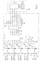
- the signals from the proximity switches 72 and the stuffer switch 70 are used in the mistie detector, which comprises a circuit board 74 ( Figure 3) for analyzing these baler signals and providing a warning signal to the operator when a defective strand condition has been detected.
- the circuit board 74 includes a microprocessor 75, which may be of the Microchip type PIC16C73, which is provided with erasable memory means into which a program can be loaded in accordance with the Appendix attached hereto.
- the microprocessor 75 comprises a set of analogous input ports to which the proximity switches 72 are connected via a diode-protected resistor circuits 76.
- the stuffer switch 70 is connected to a digital input port of the microprocessor 75 via a similar resistor circuit 76 and a comparator 77. While the stuffer mechanism 20 is cycling, the switch 70 is opened and a HIGH signal is provided by the comparator 77 to the digital input pin of the microprocessor.
- the output gates of the microprocessor 75 are connected to an electronic buffer 78, such as an integrated circuit of the type ULN2003B, for relaying status information on the strands to a monitor 80.
- the latter is installed in the tractor and comprises a circuit board 81 and a liquid crystal display 82.
- the corresponding output gate of the microprocessor 75 is reset by the program and this LOW status is loaded into the buffer 78.
- the signal is passed on to the circuit board 81, which indicates on the display 82 which knotter has failed.
- Such visual mistie indication may be combined with an audible signal to attire the operator's attention. This can be realized through a buzzer incorporated into the monitor 80.
- the program loaded into the microprocessor 75 verifies the status of the stuffer switch signal.
- the stuffer mechanism 20 When the stuffer mechanism 20 is in its home position (StufferDetector LOW) the signals coming from the strand proximity switches 72 are disregarded, thereby preventing that stray signals which are not related to an actual movement of the crop package in the baling chamber 18 would influence the mistie detection.
- Such stray signals may occur when one of the ribs of the roller 54 happens to stop in an area wherein actuation or deactuation of the switch 72 is not precisely defined, and vibrations of the baler 10 oscillate the roller surface.
- the stuffer mechanism 20 By the time the stuffer mechanism 20 has completed the stuffing cycle and returns to its home position, the newly introduced charge has been engaged by the plunger 24 and the package in the baling chamber 18 has been pushed rearwardly. The movement of the strands 34, 35 should be terminated by then.
- the program checks how many of the four strands 34 actually moved during the stuffer cycle. A variable called Zero is loaded with the number of strands for which no motion has been perceived. In case a number of strands did not move (Zero smaller than a predetermined value), the measurement results are disregarded and all variables RopeCounter_i are cleared.
- the predetermined value may be set equal to 3, such that intervals during which more than two strands 34 did not move are disregarded.
- This program step prevents that random signals distort the results of the mistie detection.
- the tying mechanism 30 takes a few stuffer operations to lower the slack take-up arms 61 and start supplying fresh binding material through the tensioning devices 52. Not all strands 34 are tensioned and start moving at the same instant.
- the mistie detection skips the time interval during which no uniform supply of twine material may be expected.
- a variable named StufferCounter is incremented and the values of RopeCounter_i are added to variables RopeSum_i, into which the pulse counts are accumulated. Thereafter the RopeCounter_i and Zero values are cleared.
- the program checks whether the variable StufferCounter has reached a predetermined value StufferSpan. For the sake of the description this value has been set to three, but smaller or larger values are also envisageable. After three stuffer cycles which embraced movement of the required number of binding strands, the program calculates the mean value of the four RopeSum_i values and sets a flag MeanRopeCountFlag.
- the program compares each single value RopeSum_i, indicative of the supplied length of each strand 34, to a threshold value, which is set equal to a percentage of the calculated mean value.
- the percentage is defined through a predetermined margin value RopeCountMargin, which here has been set equal to 60 %.
- the threshold value is equal to 40 % of the mean value.
- a corresponding flag MistieFlag_i is set. Otherwise the MistieFlag_i is reset. In both cases the variable RopeSum_i is reset to zero for starting a new accumulation of pulse counts during the next stuffer operations.
- MistieFlags are checked for producing a high or low value at the four output pins of the microprocessor 75. These values are stored in the buffer 78 and read by the circuit board 81 of the monitor 80. Any mistie indication is relayed to the display 82 in order to alert the operator.
- the tying mechanism 30 may be equipped with a set of vibration sensors 86 which are installed in front of the tensioning devices 52.
- Sensor 86 has a spiralled sensing member 87 through which the strand 34 is guided.
- the transverse vibrations of a strand 34 which is being supplied to the baling chamber 18 are transmitted upon the member 87 to which a piezo-electric element has been affixed.
- the signals from this element are thus indicative of the movement of the corresponding strand 34.
- the signals from the vibration sensors 86 are compared by a microprocessor, which will generate a mistie indication if during a time interval no movement of one of the strands has been sensed, while proper movement is sensed of a predetermined minimum number of strands 34.
- the time interval during which the twine supply is tested may also be delimited by the cycling of the stuffer mechanism 20.
- the microprocessor then monitors the output of the sensors 86 while the mechanism has left its home position. The signals are accumulated during a predetermined number of stuffer cycles and then compared to each other to trace any substantially deviating values. In case such anomalies are found a mistie indication is generated by the microprocessor.
- baling chamber may also be used in other types of agricultural balers in which a plurality of strands is supplied to the baling chamber.
- the microprocessor 75 may also register the length of the time intervals during which signals are generated and then compare the summed time values to establish a failure of any the strands 34. In such case it is not necessary to count the pulses from the proximity switches 70 or the vibrations sensors 86. The microprocessor 75 only has to establish the length of each pulse train.
- the operation of the stuffer mechanism 20 can also be detected by a sensor which is actuated by another portion of the stuffer mechanism, e.g. by the means for establishing whether a complete charge has been formed in the duct 16 and coupling the stuffer mechanism 20 to the drive mechanism.
- the invention may also be used in mechanisms for tying other kinds of binding material around the crop packages. For instance one may use wires instead of twine material and wire twisters instead of twine knotters.
- the proximity switches 72 may also be replaced with other sensors for sensing the rotation of a twine guide wheel; such sensors may include Hall sensors or optical sensors in combination with a light source.
Landscapes
- Life Sciences & Earth Sciences (AREA)
- Environmental Sciences (AREA)
- Basic Packing Technique (AREA)
Claims (25)
- Détecteur de défaut de nouage (10) pour une botteleuse agricole, comprenant :caractérisé en ce que :une chambre de bottelage (18);des moyens (20) pour charger des charges successives de matériau de récolte dans ladite chambre de bottelage (18) afin d'y former des balles dudit matériau de récolte ; etdes moyens (30) destinés à fournir une pluralité de brins de matériau de ligature (34) auxdites balles de matériau de récolte afin de constituer une pluralité de boucles autour d'elles ;
ledit détecteur de défaut de nouage comprenant des moyens (72/86) pour détecter un état desdits brins (34); etlesdits moyens de détection (72/86) détectent le mouvement desdits brins (34) durant leur acheminement vers et/ou autour desdites balles et génèrent des signaux de sortie indicatifs de celui-ci ; etledit détecteur de défaut de nouage comprend en outre des moyens (74) permettant de comparer lesdits signaux de sortie et de générer un signal d'indication de défaut de nouage lorsque le mouvement de l'un des brins (34) s'écarte de manière substantielle du mouvement des autres brins (34). - Détecteur de défaut de nouage suivant la revendication 1, caractérisé en ce que lesdits moyens de détection comprennent des capteurs de vibrations (86) détectant le mouvement transversal desdits brins induits par le déplacement longitudinal desdits brins (34) durant leur acheminement vers et/ou autour desdites balles.
- Détecteur de défaut de nouage suivant la revendication 2, caractérisé en ce que lesdits capteurs de vibrations (86) comprennent un membre (87) traversé par l'un desdits brins et un élément piézo-électrique qui est raccordé de manière opérationnelle audit membre.
- Détecteur de défaut de nouage suivant la revendication 1, caractérisé en ce que lesdits moyens de détection comprennent des moyens (72) permettant de détecter le déplacement longitudinal des brins acheminés vers et/ou autour desdites balles.
- Détecteur de défaut de nouage suivant la revendication 4, caractérisé en ce que lesdits moyens de détection comprennent des capteurs (72) qui surveillent le mouvement des roues de guidage (54) le long desquelles lesdits brins sont acheminés vers et/ou autour desdites balles de matériau de récolte.
- Détecteur de défaut de nouage suivant la revendication 5, caractérisé en ce que lesdites roues de guidage (54) comprennent une surface crénelée d'entraínement des brins et lesdits capteurs de surveillance comprennent des interrupteurs de proximité (72) dirigés vers ladite surface crénelée pour détecter la proximité d'une dent de ladite surface faisant face audit interrupteur (72).
- Détecteur de défaut de nouage suivant la revendication 5 ou 6, caractérisé en ce que les roues de guidage (54) appliquent une pré-tension auxdits brins (34).
- Détecteur de défaut de nouage suivant l'une quelconque des revendications 4 à 7, caractérisé en ce qu'il comprend des moyens (75) pour déterminer les valeurs de longueur indicatives de la longueur de chaque brin acheminée durant un intervalle de temps ou une pluralité d'intervalles de temps.
- Détecteur de défaut de nouage suivant la revendication 8, caractérisé en ce que :ladite botteleuse comprend des moyens (70) détectant le fonctionnement d'un composant mécanique (20) de ladite botteleuse (10) et délivrant un signal indicatif de celui-ci auxdits moyens (75) pour déterminer les valeurs de longueur ; etledit intervalle de temps est délimité par un nombre prédéterminé de mouvements dudit composant mécanique (20).
- Détecteur de défaut de nouage suivant la revendication 9, caractérisé en ce que lesdits moyens (75) pour déterminer les valeurs de longueur ne prennent en considération que les longueurs de brins (34) acheminés durant l'intervalle ou les intervalles pendant lesquels ledit composant mécanique est en fonctionnement.
- Détecteur de défaut de nouage suivant la revendication 9 ou 10, caractérisé en ce que ledit composant mécanique est une partie (71) desdits moyens de chargement (20).
- Détecteur de défaut de nouage suivant l'une quelconque des revendications 8 à 11, caractérisé en ce que lesdits moyens (75) pour déterminer les valeurs de longueur ignorent les longueurs des brins (34) acheminés pendant les intervalles durant lesquels les moyens de détection (72) n'ont détecté aucun mouvement pour plus d'un nombre prédéterminé de brins.
- Détecteur de défaut de nouage suivant la revendication 12, caractérisé en ce que ledit nombre prédéterminé de brins (34) est égal à deux.
- Détecteur de défaut de nouage suivant l'une quelconque des revendications 8 à 13, caractérisé en ce que lesdits moyens de comparaison (74) comparent les valeurs de longueur déterminées pour chaque brin (34) à une valeur seuil et génèrent une indication de défaut de nouage lorsqu'une valeur de longueur est inférieure à ladite valeur de seuil.
- Détecteur de défaut de nouage suivant la revendication 14, caractérisé en ce que ladite valeur de seuil est un pourcentage prédéterminé de la valeur moyenne des valeurs de longueur déterminées pour tous les brins.
- Méthode destinée à détecter un état de brin défectueux dans une botteleuse agricole (10), qui comprend :une chambre de bottelage (18);des moyens (20) pour charger des charges successives de matériau de récolte dans ladite chambre de bottelage (18) afin d'y former des balles dudit matériau de récolte ; etdes moyens (30) destinés à fournir une pluralité de brins de matériau de ligature (34) auxdites balles de matériau de récolte afin de constituer une pluralité de boucles autour d'elles ;
ladite méthode étant caractérisée en ce qu'elle comprend les étapes de, dans n'importe quel ordre approprié :i) détecter les mouvements desdits brins (34) lorsqu'ils sont acheminés vers et/ou autour desdites balles ;ii) générer des signaux de sortie indicatifs desdits mouvements ;iii) comparer les mouvements desdits brins (34) ; etiv) générer une indication de défaut de nouage lorsque le mouvement d'un brin (34) s'écarte de manière substantielle du mouvement des autres brins (34). - Méthode suivant la revendication 16, caractérisée en ce que l'étape de détection (i) comprend la détection des vibrations transversales induites par les mouvements longitudinaux desdits brins.
- Méthode suivant la revendication 17, caractérisée en ce que ladite étape de détection (i) comprend le guidage des brins le long de membres d'un capteur de vibrations.
- Méthode suivant la revendication 16, caractérisée en ce que l'étape de détection (i) comprend la détection du mouvement longitudinal desdits brins.
- Méthode suivant la revendication 18,
caractérisée par l'étape ultérieure de :et également caractérisée en ce que :déduire desdits signaux de sortie des valeurs indicatives des longueurs de brins (34) acheminés durant un intervalle de temps ou une pluralité d'intervalles de temps ;l'étape de comparaison (iii) comprend la comparaison desdites valeurs de longueur à une valeur seuil ; etl'étape de génération (iv) comprend la génération d'une indication de défaut de nouage lorsque l'une desdites valeurs de longueur déterminée est inférieure à ladite valeur seuil. - Méthode suivant la revendication 20, caractérisée en ce qu'elle comprend les étapes ultérieures de :détection du fonctionnement d'un composant de ladite botteleuse ;utilisation pour ledit intervalle de temps de l'intervalle correspondant à un nombre prédéterminé de mouvements d'un composant mécanique (20) de ladite botteleuse (10).
- Méthode suivant la revendication 21,
caractérisée par les étapes ultérieures de :déterminer pendant chaque intervalle combien de brins (34) ont réellement bougé ; etignorer l'intervalle et les mouvements de brins pendant celui-ci pour la détermination desdites valeurs de longueur si plus d'un nombre prédéterminé de brins (34) n'ont pas bougé. - Méthode suivant la revendication 22, caractérisée en ce que ledit nombre prédéterminé de brins (34) est égal à deux.
- Méthode suivant l'une quelconque des revendications 21 à 23, caractérisée en ce que ledit composant mécanique est un composant desdits moyens de chargement.
- Méthode suivant l'une quelconque des revendications 20 à 24, caractérisée en ce que ladite valeur seuil est un pourcentage prédéterminé de la valeur moyenne de toutes les longueurs déterminées.
Applications Claiming Priority (2)
| Application Number | Priority Date | Filing Date | Title |
|---|---|---|---|
| GB9701681A GB2321425A (en) | 1997-01-28 | 1997-01-28 | Detecting mis-ties in a baler |
| GB9701681 | 1997-01-28 |
Publications (2)
| Publication Number | Publication Date |
|---|---|
| EP0856248A1 EP0856248A1 (fr) | 1998-08-05 |
| EP0856248B1 true EP0856248B1 (fr) | 2002-03-27 |
Family
ID=10806674
Family Applications (1)
| Application Number | Title | Priority Date | Filing Date |
|---|---|---|---|
| EP98200140A Expired - Lifetime EP0856248B1 (fr) | 1997-01-28 | 1998-01-20 | Dispositif de contrôle du liage des balles dans une presse agricole |
Country Status (4)
| Country | Link |
|---|---|
| US (1) | US5988053A (fr) |
| EP (1) | EP0856248B1 (fr) |
| DE (1) | DE69804362T2 (fr) |
| GB (1) | GB2321425A (fr) |
Cited By (2)
| Publication number | Priority date | Publication date | Assignee | Title |
|---|---|---|---|---|
| DE102016117755B4 (de) | 2016-04-12 | 2022-12-08 | Hermann Schwelling | Verfahren zum Steuern der Ballen-Länge sowie Ballenpresse zur Anwendung dieses Verfahrens |
| EP4602909A1 (fr) * | 2024-02-15 | 2025-08-20 | Usines Claas France S.A.S | Presse à balles carrées agricole pour traiter des produits de récolte en balles rectangulaires |
Families Citing this family (10)
| Publication number | Priority date | Publication date | Assignee | Title |
|---|---|---|---|---|
| DE10047336A1 (de) * | 2000-09-23 | 2002-04-11 | Paals Packpressen Fabrik Gmbh | Ballenpresse für loses Preßgut |
| US6782807B2 (en) * | 2003-01-15 | 2004-08-31 | Deere & Company | Knot-relieving twine tensioner for baler |
| US9560808B2 (en) | 2011-04-19 | 2017-02-07 | Cnh Industrial America Llc | System for controlling bale forming and wrapping operations |
| US8495956B1 (en) * | 2012-10-30 | 2013-07-30 | Deere & Company | Twine tensioning system for a baler |
| US8671834B1 (en) * | 2012-11-30 | 2014-03-18 | Deere & Company | Twine tensioner arm position sensor arrangement |
| BE1021139B1 (nl) | 2013-04-02 | 2016-01-05 | Cnh Industrial Belgium Nv | Baalmeetsysteem en-werkwijze |
| US11991958B2 (en) | 2019-10-22 | 2024-05-28 | Great Plains Manufacturing, Inc. | Systems and methods for detecting knotter misties |
| EP3932181A1 (fr) * | 2020-07-01 | 2022-01-05 | AGCO Corporation | Ensemble de réglage de la tension d'une ficelle |
| EP3932183B1 (fr) | 2020-07-01 | 2024-09-18 | AGCO Corporation | Ensemble de tension de ficelle |
| US20250366402A1 (en) * | 2024-05-31 | 2025-12-04 | Agco Corporation | Mis-Tie Detection for Baler Knotter |
Family Cites Families (15)
| Publication number | Priority date | Publication date | Assignee | Title |
|---|---|---|---|---|
| US4074623A (en) * | 1976-11-16 | 1978-02-21 | Hesston Corporation | Method for binding a crop bale |
| US4196661A (en) * | 1978-11-24 | 1980-04-08 | Hesston Corporation | Knotting monitor for crop balers |
| DD208748A1 (de) * | 1982-07-28 | 1984-04-11 | Hubert Prellwitz | Fehlbindungsanzeige fuer ballenpressen |
| US4756235A (en) * | 1986-09-15 | 1988-07-12 | Cartner Jack O | Motor control valve assembly |
| DE3640696A1 (de) * | 1986-11-28 | 1988-06-09 | Zweegers & Zonen P J | Rundballenpresse |
| US4765235A (en) * | 1987-04-15 | 1988-08-23 | Hay & Forage Industries | Monitoring system for detecting malfunction of knotting mechanism on a crop baler |
| US4753464A (en) * | 1987-06-01 | 1988-06-28 | Ford New Holland, Inc. | Mistie detector and indicator system |
| US4753463A (en) * | 1987-06-01 | 1988-06-28 | Ford New Holland, Inc. | Mistie detection and indication |
| US4998961A (en) * | 1987-09-29 | 1991-03-12 | Hay & Forage Industries | Twine monitoring assembly for round balers |
| US4885991A (en) * | 1988-07-25 | 1989-12-12 | Borba Frank X | Device for sensing malfunction of tying apparatus on hay baler |
| DE3918065A1 (de) * | 1989-06-02 | 1990-12-06 | Lindemann Maschfab Gmbh | Vorrichtung zum umschnueren von in einer ballenpresse hergestellten ballen |
| DD289917A5 (de) * | 1989-12-15 | 1991-05-16 | Fz F. Mechanis. U. Energieanwendung I. D. Landwirtsch.,De | Verfahren und vorrichtung zur fehlbindungskontrolle an ballenpressen mit zweifadenbindung |
| DE4116619C2 (de) * | 1991-05-22 | 1999-11-04 | Claas Ohg | Vorrichtung zur Bildung eines Preßballens aus landwirtschaftlichem Erntegut |
| US5388504A (en) * | 1993-08-23 | 1995-02-14 | Agco Corporation | Twine wrap control for round baler |
| US5783816A (en) * | 1996-10-09 | 1998-07-21 | Mcpherson; Bobby Roy | Measuring device for a hay baler |
-
1997
- 1997-01-28 GB GB9701681A patent/GB2321425A/en not_active Withdrawn
-
1998
- 1998-01-15 US US09/007,338 patent/US5988053A/en not_active Expired - Lifetime
- 1998-01-20 EP EP98200140A patent/EP0856248B1/fr not_active Expired - Lifetime
- 1998-01-20 DE DE69804362T patent/DE69804362T2/de not_active Expired - Lifetime
Cited By (2)
| Publication number | Priority date | Publication date | Assignee | Title |
|---|---|---|---|---|
| DE102016117755B4 (de) | 2016-04-12 | 2022-12-08 | Hermann Schwelling | Verfahren zum Steuern der Ballen-Länge sowie Ballenpresse zur Anwendung dieses Verfahrens |
| EP4602909A1 (fr) * | 2024-02-15 | 2025-08-20 | Usines Claas France S.A.S | Presse à balles carrées agricole pour traiter des produits de récolte en balles rectangulaires |
Also Published As
| Publication number | Publication date |
|---|---|
| DE69804362D1 (de) | 2002-05-02 |
| DE69804362T2 (de) | 2004-04-29 |
| GB2321425A (en) | 1998-07-29 |
| US5988053A (en) | 1999-11-23 |
| GB9701681D0 (en) | 1997-03-19 |
| EP0856248A1 (fr) | 1998-08-05 |
Similar Documents
| Publication | Publication Date | Title |
|---|---|---|
| US8671834B1 (en) | Twine tensioner arm position sensor arrangement | |
| EP0856248B1 (fr) | Dispositif de contrôle du liage des balles dans une presse agricole | |
| US4765235A (en) | Monitoring system for detecting malfunction of knotting mechanism on a crop baler | |
| US8434289B2 (en) | Sensor for detection of wrapping on bale | |
| US7337713B1 (en) | Bale wrapping pattern controller and method | |
| US7878557B2 (en) | Knotter for a baler | |
| US4196661A (en) | Knotting monitor for crop balers | |
| US4161097A (en) | Knotter with improved billhook and actuation mechanism | |
| EP0857414B1 (fr) | Système pour contrôler la densité des balles dans une presse à balles | |
| EP2727456B1 (fr) | Système de tension pour presse à balles | |
| EP0040970B1 (fr) | Appareil pour détecter des défauts du lieur d'une presse à balles | |
| EP3114921B1 (fr) | Système noueur de ramasseuse-presse agricole | |
| US20250366402A1 (en) | Mis-Tie Detection for Baler Knotter | |
| US12302798B2 (en) | Twine tension monitoring apparatus | |
| US4234219A (en) | Knotter with improved billhook and actuation mechanism | |
| EP4091434A1 (fr) | Presse à balles | |
| US4372589A (en) | Knotter apparatus | |
| EP3932182B1 (fr) | Ensemble de soulagement de tension de ficelle | |
| US20230345880A1 (en) | Billhook for Baler Knotter | |
| GB2079329A (en) | Knotters | |
| GB2124261A (en) | Knotters | |
| GB2081312A (en) | Knotters | |
| HU202155B (en) | Apparatus for controlling the bale binding at pickup balers | |
| GB1600418A (en) | Knotters |
Legal Events
| Date | Code | Title | Description |
|---|---|---|---|
| PUAI | Public reference made under article 153(3) epc to a published international application that has entered the european phase |
Free format text: ORIGINAL CODE: 0009012 |
|
| AK | Designated contracting states |
Kind code of ref document: A1 Designated state(s): DE FR GB IT |
|
| AX | Request for extension of the european patent |
Free format text: AL;LT;LV;MK;RO;SI |
|
| 17P | Request for examination filed |
Effective date: 19990122 |
|
| AKX | Designation fees paid |
Free format text: DE FR GB IT |
|
| RBV | Designated contracting states (corrected) |
Designated state(s): DE FR GB IT |
|
| GRAG | Despatch of communication of intention to grant |
Free format text: ORIGINAL CODE: EPIDOS AGRA |
|
| 17Q | First examination report despatched |
Effective date: 20010504 |
|
| GRAG | Despatch of communication of intention to grant |
Free format text: ORIGINAL CODE: EPIDOS AGRA |
|
| GRAG | Despatch of communication of intention to grant |
Free format text: ORIGINAL CODE: EPIDOS AGRA |
|
| GRAH | Despatch of communication of intention to grant a patent |
Free format text: ORIGINAL CODE: EPIDOS IGRA |
|
| GRAH | Despatch of communication of intention to grant a patent |
Free format text: ORIGINAL CODE: EPIDOS IGRA |
|
| REG | Reference to a national code |
Ref country code: GB Ref legal event code: IF02 |
|
| GRAA | (expected) grant |
Free format text: ORIGINAL CODE: 0009210 |
|
| AK | Designated contracting states |
Kind code of ref document: B1 Designated state(s): DE FR GB IT |
|
| REF | Corresponds to: |
Ref document number: 69804362 Country of ref document: DE Date of ref document: 20020502 |
|
| ET | Fr: translation filed | ||
| PLBE | No opposition filed within time limit |
Free format text: ORIGINAL CODE: 0009261 |
|
| STAA | Information on the status of an ep patent application or granted ep patent |
Free format text: STATUS: NO OPPOSITION FILED WITHIN TIME LIMIT |
|
| 26N | No opposition filed |
Effective date: 20021230 |
|
| REG | Reference to a national code |
Ref country code: FR Ref legal event code: CD |
|
| REG | Reference to a national code |
Ref country code: DE Ref legal event code: R082 Ref document number: 69804362 Country of ref document: DE Representative=s name: G. KOCH UND KOLLEGEN, DE |
|
| REG | Reference to a national code |
Ref country code: DE Ref legal event code: R082 Ref document number: 69804362 Country of ref document: DE Representative=s name: G. KOCH UND KOLLEGEN, DE Effective date: 20140428 Ref country code: DE Ref legal event code: R081 Ref document number: 69804362 Country of ref document: DE Owner name: CNH INDUSTRIAL BELGIUM NV, BE Free format text: FORMER OWNER: CNH BELGIUM NV, ZEDELGEM, BE Effective date: 20140428 |
|
| REG | Reference to a national code |
Ref country code: FR Ref legal event code: CD Owner name: CNH INDUSTRIAL BELGIUM NV Effective date: 20140725 |
|
| REG | Reference to a national code |
Ref country code: DE Ref legal event code: R084 Ref document number: 69804362 Country of ref document: DE |
|
| REG | Reference to a national code |
Ref country code: GB Ref legal event code: 746 Effective date: 20150123 |
|
| REG | Reference to a national code |
Ref country code: DE Ref legal event code: R084 Ref document number: 69804362 Country of ref document: DE Effective date: 20150117 |
|
| REG | Reference to a national code |
Ref country code: FR Ref legal event code: PLFP Year of fee payment: 19 |
|
| PGFP | Annual fee paid to national office [announced via postgrant information from national office to epo] |
Ref country code: IT Payment date: 20160105 Year of fee payment: 19 |
|
| PGFP | Annual fee paid to national office [announced via postgrant information from national office to epo] |
Ref country code: GB Payment date: 20160114 Year of fee payment: 19 Ref country code: FR Payment date: 20160112 Year of fee payment: 19 |
|
| PGFP | Annual fee paid to national office [announced via postgrant information from national office to epo] |
Ref country code: DE Payment date: 20170128 Year of fee payment: 20 |
|
| GBPC | Gb: european patent ceased through non-payment of renewal fee |
Effective date: 20170120 |
|
| REG | Reference to a national code |
Ref country code: FR Ref legal event code: ST Effective date: 20170929 |
|
| PG25 | Lapsed in a contracting state [announced via postgrant information from national office to epo] |
Ref country code: FR Free format text: LAPSE BECAUSE OF NON-PAYMENT OF DUE FEES Effective date: 20170131 |
|
| PG25 | Lapsed in a contracting state [announced via postgrant information from national office to epo] |
Ref country code: GB Free format text: LAPSE BECAUSE OF NON-PAYMENT OF DUE FEES Effective date: 20170120 |
|
| REG | Reference to a national code |
Ref country code: DE Ref legal event code: R071 Ref document number: 69804362 Country of ref document: DE |
|
| PG25 | Lapsed in a contracting state [announced via postgrant information from national office to epo] |
Ref country code: IT Free format text: LAPSE BECAUSE OF NON-PAYMENT OF DUE FEES Effective date: 20170120 |