EP0856328A2 - Dispositif de traitement de fluide - Google Patents
Dispositif de traitement de fluide Download PDFInfo
- Publication number
- EP0856328A2 EP0856328A2 EP98300074A EP98300074A EP0856328A2 EP 0856328 A2 EP0856328 A2 EP 0856328A2 EP 98300074 A EP98300074 A EP 98300074A EP 98300074 A EP98300074 A EP 98300074A EP 0856328 A2 EP0856328 A2 EP 0856328A2
- Authority
- EP
- European Patent Office
- Prior art keywords
- tubular portion
- fluid treatment
- housing
- filter
- assembly according
- Prior art date
- Legal status (The legal status is an assumption and is not a legal conclusion. Google has not performed a legal analysis and makes no representation as to the accuracy of the status listed.)
- Withdrawn
Links
Images



Classifications
-
- A—HUMAN NECESSITIES
- A61—MEDICAL OR VETERINARY SCIENCE; HYGIENE
- A61M—DEVICES FOR INTRODUCING MEDIA INTO, OR ONTO, THE BODY; DEVICES FOR TRANSDUCING BODY MEDIA OR FOR TAKING MEDIA FROM THE BODY; DEVICES FOR PRODUCING OR ENDING SLEEP OR STUPOR
- A61M16/00—Devices for influencing the respiratory system of patients by gas treatment, e.g. ventilators; Tracheal tubes
- A61M16/10—Preparation of respiratory gases or vapours
- A61M16/105—Filters
-
- A—HUMAN NECESSITIES
- A61—MEDICAL OR VETERINARY SCIENCE; HYGIENE
- A61M—DEVICES FOR INTRODUCING MEDIA INTO, OR ONTO, THE BODY; DEVICES FOR TRANSDUCING BODY MEDIA OR FOR TAKING MEDIA FROM THE BODY; DEVICES FOR PRODUCING OR ENDING SLEEP OR STUPOR
- A61M16/00—Devices for influencing the respiratory system of patients by gas treatment, e.g. ventilators; Tracheal tubes
- A61M16/10—Preparation of respiratory gases or vapours
- A61M16/105—Filters
- A61M16/1055—Filters bacterial
Definitions
- This invention relates to fluid-treatment assemblies of the kind comprising an outer housing and a fluid treatment element located in the housing between a first port and a second port.
- Filters are used in medical breathing applications, to filter air or gas supplied to and from a patient. In order to ensure that bacteria and viruses are completely blocked by the filter, it must have a high efficiency, which leads to an increased flow resistance. Flow resistance can be minimized by increasing the area of the filter, so medical filters with acceptable filtering efficiency and flow resistance tend to be bulky. This is generally undesirable because it obstructs access to the patient and is more likely to impede other equipment in the vicinity of the patient. Heat and moisture exchangers (HMEs) also tend to be bulky when they have a low flow resistance and a high exchange efficiency.
- HMEs Heat and moisture exchangers
- a :fluid treatment assembly of the above-specified kind, characterised in that the housing is of tubular shape, that the fluid treatment element has a tubular portion extending coaxially within the housing, that one end of the tubular portion is sealed with the housing between the first and second ports, and that the other end of the tubular portion is closed such that fluid passing through the housing between the first and second ports must flow through the thickness of the fluid treatment element.
- the outer housing and the tubular portion may be flexible.
- the tubular portion may include an outer tubular portion extending from the one end and an inner tubular portion joined with the other end of the outer tubular portion and extending coaxially within the outer tubular portion.
- the outer tubular portion preferably tapers from the one end to the other end, the inner tubular portion tapering in the opposite direction such as to provide a tapering annular recess between the outer and inner tubular portions.
- the tubular portion may be corrugated.
- the tubular portion may be a radially-pleated ruff of conical shape.
- the tubular portion may be provided by a plurality of conical elements joined with one another end-to-end.
- the tubular portion may be provided by a helically-wound strip of material.
- the tubular portion may be provided by a tube of filter material that is creased through its thickness to increase its surface area and flexibility.
- the fluid treatment element is preferably a medical breathing gas filter and may include an HME element, such as a foam.
- an assembly including a tracheal tube 1 (only a part of which is shown) having a port or connector 2 at its machine end, which is connected to a right-angle coupling 3 at the patient end of a catheter mount 4.
- the catheter mount has a length of flexible, corrugated tubing 5 extending from the patient end connector 2 to a machine end port or connector 6, which, in turn, is connected to a connector 7 at the patient end of ventilation tubing 8 by which medical breathing gas is supplied to and from the assembly.
- the catheter mount 4 includes a filter assembly 10 extending longitudinally within the catheter mount forwardly along about half its length.
- the catheter mount 4 provides an outer housing for the filter assembly 10 and the connectors 2 and 6 form ports for gas passage through the filter assembly.
- the filter assembly 10 has a rigid, circular mounting plate 11 at its rear end, which is perforated by two D-shape apertures 12.
- a filter element 13 of a conventional filter paper or fabric material is joined at one end to the forward side of the plate 11 and is closed at its other end.
- the filter element 13 comprises an outer tube 14 of conical shape, tapering slightly to a reduced diameter at its other, forward end 15 where it is joined with an inner tube 16.
- the term "cone” or “conical” is used to include part-conical, such as frusto-conical shapes.
- the inner tube 16 is similarly tapered and extends rearwardly coaxially within the outer tube 14, having a reduced diameter at its rear end 17.
- the inside of the inner tube 16 is open at the forward end of the filter element 13.
- the filter element 13, in this example, is formed as a single conical member, the smaller end being everted within the larger end to form the two concentric outer and inner tubes 14 and 16.
- the inner and outer tubes could be formed separately and subsequently joined together.
- the rear end 17 of the inner tube 16 is sealed closed, such as by being joined with a central boss 18 on the plate 11.
- the two apertures 12 open into the annular recess 19 between the outer and inner tubes 14 and 16.
- the filter mounting plate 11 is sealed around its outer edge into the machine end coupling 6 so that all gas flowing along the catheter mount 4 must pass through the apertures 12 and hence through the thickness of the wall of either the outer or inner tube 14 or 16.
- Gas flowing to the patient flows from the annular space 19, either inwardly through the inner tube 16, or outwardly through the outer tube 14.
- Gas flowing in the opposite direction, from the patient flows through the wall of the outer or inner tube 14 or 16 into the annular space 19.
- the external diameter of the outer tube 14 is chosen to leave sufficient clearance for gas to flow between the outside of the tube and the inside of the corrugated tubing 5.
- the material forming the filter element 13 is flexible or bendable, thereby enabling the catheter mount 4 to be flexed without damage either to the tubing 5 or to the filter assembly 10.
- the coaxial arrangement of the outer and inner filter tubes 14 and 16 enables a relatively large filter area to be achieved with a relatively small cross-sectional dimension, thereby enabling the filter to be provided within the catheter mount itself.
- the assembly could also be given heat and moisture exchange properties by including an HME material, such as a flexible hygroscopic foam, in the tubing 5 forwardly of the filter element 13.
- HME material such as a flexible hygroscopic foam
- FIG. 3 there is shown a modified filter element 20 having inner and outer conical tubes 21 and 22, in which the two tubes are corrugated concentrically. This enables the same surface area to be produced in a shorter length and also improves the flexibility of the filter element.
- the space between inner and outer tubes 21 and 22 contains an HME material 23, such as a hygroscopic foam.
- This filter element 20 is located in a housing between inlet and outlet ports.
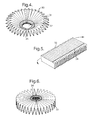
- FIG 4 there is shown an alternative tubular filter element 30 of conical shape, which has radial pleats 31 extending out from the centre 32, which is sealed closed.
- the outer edge of the filter element 30 is sealed to a housing between two ports (not shown), such as by means of a hot-melt adhesive.
- the filter element 30 is made by taking a rectangular, laterally-pleated pack 33 and depositing a line 34 of a hot-melt adhesive, or similar material, longitudinally close to one edge, as shown in Figure 5.
- Opposite ends of the pleated pack 33 are then folded around the edge along which the line 34 of adhesive has been deposited and are sealed together to form a flat ruff, as shown in Figure 6.
- the centre of the ruff is then displaced down relative to the outer edge, to form the cone shape in Figure 4, and the centre is closed to prevent the direct passage of gas through it. It could be closed with additional filter material.
- a filter element 40 which is a modified form of the radially-pleated filter element 30 in Figure 4.
- the filter element 40 differs from the other element in that its centre 41 is inverted relative to its outside, in a similar manner to the filters shown in Figures 2 and 3.
- An assembly including a filter element 40 of the kind shown in Figure 7 may also include an HME element 42, as shown in Figure 8.
- the HME element 42 is of conical shape and is nested within the filter element.
- FIG. 9 there is shown a filter assembly with five conical, radially-pleated filter elements 50 to 54 of the kind similar to that shown in Figure 4.
- Four of the filter elements 50 to 53 have their centres left open and are joined end-to-end.
- the first filter element 50 in the sequence has its outer edge 55 sealed to the inside of a housing 56, opposite ends of which provide respective inlet or outlet ports of the filter assembly.
- the first filter element 50 has its centre aperture 57 sealed to the centre aperture 58 of the next element 51, which is oppositely oriented to the first element 50.
- the outer edge 59 of the second element 51 is sealed with the outer edge 60 of the third element 52, which is oriented in the same sense as the first element 50.
- the centre 61 of the third element 52 is sealed with the centre 62 of the fourth element 53, which is oriented in the same sense as the second filter element 51.
- the outer edge 63 of the fourth filter element 53 is sealed with the outer edge 64 of the last element.
- the last element 54 is oriented in the same sense as the first element and has its centre 65 closed.
- the second to fifth filter elements 51 to 54 are elongated slightly compared with the first element 50, so that their diameters, at their larger ends are less than the internal diameter of the housing 56.
- filter element 70 is of conical shape and comprises a strip of filter material 71 wound helically with the width of the strip extending parallel with the axis of the helix and with adjacent turns of the strip overlapping and sealed with one another.
- the strip 71 may be flat or it may have channel-shape lips 72 extending along opposite edges.
- the filter element 70 is made in the manner shown in Figure 11, by winding the strip of filter material initially into flat coil and sealing the outer end of the strip to the underlying turn with a hot-melt adhesive.
- the coil is placed in a jig 73 and a conical former 74 is pushed down on the centre of the coil so as to push out the centre of the coil and form it into a conical shape.
- strip 71 has lips 72, interlocking of the lips of adjacent turns will limit the extent of extension of the coil.
- a line of hot-melt adhesive, or similar material is then applied along the edge of the strip 71 where it overlaps the underlying turn of the strip, so as to seal the strip and retain it in its helical configuration.
- the inner, centre of the coil is also closed in the same way.
- a filter element 80 comprising a single tube 81 of filter material attached around its mouth at one end 82 to a perforated plate 83, which is, in turn sealed around its outside to the inside of a housing 84.
- the housing 84 is of tubular shape, the tube 81 extending axially along the housing and the seal at one end of the filter tube being located between ports 85 and 86 at opposite ends of the housing.
- the other end 87 of the filter tube 81 is closed, such as by flattening the tube and sealing the flattened sides together with an adhesive.
- the wall of the tube 81 is formed along its entire length with a pattern of creases 88 through the thickness of the wall, so that an indentation in the outer surface appears as a projection on the inner surface.
- creases make the tube 81 more flexible and enable it to be used within a flexible outer housing, such as a catheter mount.
- the creases also increase the surface area of the tube compared with a tube of the same length and diameter without creases.
- the filter elements described above may be replaced with HME elements of the same shape, such as of a hygroscopic paper, or by combined filter and HME elements.
Landscapes
- Health & Medical Sciences (AREA)
- Life Sciences & Earth Sciences (AREA)
- General Health & Medical Sciences (AREA)
- Engineering & Computer Science (AREA)
- Anesthesiology (AREA)
- Biomedical Technology (AREA)
- Heart & Thoracic Surgery (AREA)
- Pulmonology (AREA)
- Hematology (AREA)
- Animal Behavior & Ethology (AREA)
- Emergency Medicine (AREA)
- Public Health (AREA)
- Veterinary Medicine (AREA)
- Infusion, Injection, And Reservoir Apparatuses (AREA)
- Filtering Materials (AREA)
- Filtering Of Dispersed Particles In Gases (AREA)
- Respiratory Apparatuses And Protective Means (AREA)
Applications Claiming Priority (2)
| Application Number | Priority Date | Filing Date | Title |
|---|---|---|---|
| GB9702058 | 1997-01-31 | ||
| GBGB9702058.0A GB9702058D0 (en) | 1997-01-31 | 1997-01-31 | Fluid-treatment assemblies |
Publications (2)
| Publication Number | Publication Date |
|---|---|
| EP0856328A2 true EP0856328A2 (fr) | 1998-08-05 |
| EP0856328A3 EP0856328A3 (fr) | 1999-05-19 |
Family
ID=10806921
Family Applications (1)
| Application Number | Title | Priority Date | Filing Date |
|---|---|---|---|
| EP98300074A Withdrawn EP0856328A3 (fr) | 1997-01-31 | 1998-01-07 | Dispositif de traitement de fluide |
Country Status (4)
| Country | Link |
|---|---|
| EP (1) | EP0856328A3 (fr) |
| JP (1) | JPH10216446A (fr) |
| AU (1) | AU5203698A (fr) |
| GB (2) | GB9702058D0 (fr) |
Cited By (10)
| Publication number | Priority date | Publication date | Assignee | Title |
|---|---|---|---|---|
| US6279570B1 (en) | 1999-03-02 | 2001-08-28 | 3M Innovative Properties Company | Filter support, assembly and system |
| EP1820529A1 (fr) * | 2006-02-17 | 2007-08-22 | General Electric Company | Unité de traitement de gaz |
| GB2414682B (en) * | 2004-06-03 | 2009-02-11 | Intersurgical Ltd | Improvements relating to medical respiratory apparatus |
| GB2452442A (en) * | 2005-06-02 | 2009-03-04 | Intersurgical Ag | Trap for respiratory apparatus |
| WO2012130436A1 (fr) * | 2011-03-29 | 2012-10-04 | Daimler Ag | Moteur à combustion interne de véhicule automobile ayant un filtre d'huile |
| WO2017192497A1 (fr) * | 2016-05-02 | 2017-11-09 | Carmen Schuller | Appareil purificateur d'air à modules de filtre flexibles |
| US20180104517A1 (en) * | 2016-10-18 | 2018-04-19 | Carmen Schuller | Air purifier apparatus with flexible filter modules |
| US11376451B2 (en) * | 2016-05-02 | 2022-07-05 | Carmen Schuller | Air purifier apparatus with flexible filter modules |
| US20230001240A1 (en) * | 2021-03-03 | 2023-01-05 | Carmen Schuller | Intelligent air purifier apparatus |
| IT202300019446A1 (it) * | 2023-09-21 | 2025-03-21 | Gvs Filter Tech Uk Ltd | Filtro dell'aria per dispositivo di respirazione |
Families Citing this family (7)
| Publication number | Priority date | Publication date | Assignee | Title |
|---|---|---|---|---|
| US8455242B2 (en) | 2010-02-22 | 2013-06-04 | Hyclone Laboratories, Inc. | Mixing system with condenser |
| JP6585616B2 (ja) * | 2014-03-21 | 2019-10-02 | ライフ テクノロジーズ コーポレイション | 流体処理システムのためのガスフィルタシステム |
| EP3466509B1 (fr) | 2014-03-21 | 2021-03-10 | Life Technologies Corporation | Systèmes de condenseur pour systèmes de traitement de fluide |
| US9457306B2 (en) | 2014-10-07 | 2016-10-04 | Life Technologies Corporation | Regulated vacuum off-gassing of gas filter for fluid processing system and related methods |
| CN108778515B (zh) | 2015-12-29 | 2020-11-17 | 生命科技股份有限公司 | 具有部分分割分隔区的柔性生物处理容器 |
| JP6836299B1 (ja) * | 2020-08-25 | 2021-02-24 | 合同会社電視工芸 | 熱交換器及び凝縮装置 |
| CA3156281A1 (fr) * | 2021-04-19 | 2022-10-19 | Andre V. Asselin | Avaaka : appareil d'evacuation anti-contaminant et kanga angelique |
Family Cites Families (13)
| Publication number | Priority date | Publication date | Assignee | Title |
|---|---|---|---|---|
| US2944547A (en) * | 1955-12-09 | 1960-07-12 | Z And W Machine Products Inc | Portable anesthesia machine, oxygen inhalator and resuscitator |
| US3713440A (en) * | 1971-01-18 | 1973-01-30 | P Nicholes | Filtration system |
| US3843523A (en) * | 1972-05-24 | 1974-10-22 | Dresen Doing Business As Sfd O | Oil filter |
| CA1062630A (fr) * | 1975-09-22 | 1979-09-18 | Joseph C. Tokar | Filtre d'air perfectionne pour vehicules routiers |
| US4297115A (en) * | 1979-09-18 | 1981-10-27 | Staclean Diffuser Company | Bag-type filter with air diffuser tubes of helical construction |
| SE434703B (sv) * | 1982-02-23 | 1984-08-13 | Gambro Engstrom Ab | Anordning for anslutning av en narkos- eller respiratorapparat till en patient |
| FR2568138B1 (fr) * | 1984-07-25 | 1986-11-14 | Are Sarl | Cartouche de filtration a surface externe en nids d'abeilles et procede de realisation |
| GB2169522B (en) * | 1985-01-11 | 1989-02-01 | Mach Control Limited | Fluid filter |
| US4764346A (en) * | 1986-12-09 | 1988-08-16 | Pioneer Medical Systems, Inc. | Disposable rebreathing canister |
| GB8630516D0 (en) * | 1986-12-22 | 1987-02-04 | Taylor N J | Tank vent screen unit |
| GB8916361D0 (en) * | 1989-07-18 | 1989-09-06 | Smiths Industries Plc | Filters |
| FR2673120B1 (fr) * | 1991-02-27 | 1993-12-31 | Fleetguard | Filtre reutilisable pour fluide ayant une fonction de filtrage et une fonction d'introduction d'additifs. |
| SE469925B (sv) * | 1992-02-21 | 1993-10-11 | Gibeck Respiration Ab | Filteranordning för anslutning till en persons andningsorgan innefattande ett hölje som innesluter ett fukt-värmeväxlande material och ett bakterieupptagande filter, som består av ett veckat, luftgenomträngligt material |
-
1997
- 1997-01-31 GB GBGB9702058.0A patent/GB9702058D0/en active Pending
-
1998
- 1998-01-07 EP EP98300074A patent/EP0856328A3/fr not_active Withdrawn
- 1998-01-08 GB GB9800268A patent/GB2321604A/en not_active Withdrawn
- 1998-01-13 AU AU52036/98A patent/AU5203698A/en not_active Abandoned
- 1998-01-23 JP JP1118298A patent/JPH10216446A/ja active Pending
Cited By (13)
| Publication number | Priority date | Publication date | Assignee | Title |
|---|---|---|---|---|
| US6279570B1 (en) | 1999-03-02 | 2001-08-28 | 3M Innovative Properties Company | Filter support, assembly and system |
| GB2414682B (en) * | 2004-06-03 | 2009-02-11 | Intersurgical Ltd | Improvements relating to medical respiratory apparatus |
| GB2452442A (en) * | 2005-06-02 | 2009-03-04 | Intersurgical Ag | Trap for respiratory apparatus |
| GB2452442B (en) * | 2005-06-02 | 2009-07-08 | Intersurgical Ag | Improvements relating to Medical Respiratory Apparatus |
| EP1820529A1 (fr) * | 2006-02-17 | 2007-08-22 | General Electric Company | Unité de traitement de gaz |
| WO2012130436A1 (fr) * | 2011-03-29 | 2012-10-04 | Daimler Ag | Moteur à combustion interne de véhicule automobile ayant un filtre d'huile |
| WO2017192497A1 (fr) * | 2016-05-02 | 2017-11-09 | Carmen Schuller | Appareil purificateur d'air à modules de filtre flexibles |
| US11376451B2 (en) * | 2016-05-02 | 2022-07-05 | Carmen Schuller | Air purifier apparatus with flexible filter modules |
| US20180104517A1 (en) * | 2016-10-18 | 2018-04-19 | Carmen Schuller | Air purifier apparatus with flexible filter modules |
| US11389676B2 (en) * | 2016-10-18 | 2022-07-19 | Carmen Schuller | Air purifier apparatus with flexible filter modules |
| US20230001240A1 (en) * | 2021-03-03 | 2023-01-05 | Carmen Schuller | Intelligent air purifier apparatus |
| IT202300019446A1 (it) * | 2023-09-21 | 2025-03-21 | Gvs Filter Tech Uk Ltd | Filtro dell'aria per dispositivo di respirazione |
| WO2025062284A1 (fr) | 2023-09-21 | 2025-03-27 | Gvs Filter Technology Uk Ltd | Dispositif de filtre à air pour dispositif respiratoire |
Also Published As
| Publication number | Publication date |
|---|---|
| GB2321604A (en) | 1998-08-05 |
| GB9800268D0 (en) | 1998-03-04 |
| GB9702058D0 (en) | 1997-03-19 |
| AU5203698A (en) | 1998-08-06 |
| EP0856328A3 (fr) | 1999-05-19 |
| JPH10216446A (ja) | 1998-08-18 |
Similar Documents
| Publication | Publication Date | Title |
|---|---|---|
| EP0856328A2 (fr) | Dispositif de traitement de fluide | |
| DE60119407T2 (de) | Filter | |
| EP1706163B1 (fr) | Circuit respiratoire a longueur reglable | |
| EP0409402B1 (fr) | Dispositifs échangeurs de chaleur et d'humidité | |
| JP3320778B2 (ja) | 質量及び/または熱の移動を行なう装置 | |
| US6051131A (en) | Flow modifier for submerged intake screen | |
| BR0212774B1 (pt) | Circuito respiratório com uma ramificação e múltiplos lúmens. | |
| JPH05196377A (ja) | 熱交換器 | |
| US6397842B1 (en) | Fluid-treatment devices | |
| JP2002525552A (ja) | 熱交換器 | |
| WO2006032656A9 (fr) | Element filtrant | |
| US6374864B1 (en) | Helically-wound conduit | |
| US20140158608A1 (en) | Filter assembly for fluid system | |
| EP1545737A1 (fr) | Ensemble sac-filtre | |
| EP0621047A2 (fr) | Oxygénateur de sang à fibres creuses | |
| EP1621224A3 (fr) | Circuit de respiration à volume et longeur réglables | |
| AU714100B2 (en) | Hollow fiber oxygenator | |
| JP4637407B2 (ja) | ストレーナ | |
| CN106457091B (zh) | 过滤器联接件 | |
| JP3812180B2 (ja) | フイルタ−収納装置 | |
| CN224194360U (zh) | 一次性使用手术用过滤器 | |
| MXPA01003371A (en) | Flow modifier for submerged intake screen | |
| JPH0232559B2 (ja) | Netsukokanki | |
| JP3058535U (ja) | 浄化用濾材フイルター支持 | |
| JPH08110180A (ja) | 熱交換器および熱交換コイル |
Legal Events
| Date | Code | Title | Description |
|---|---|---|---|
| PUAI | Public reference made under article 153(3) epc to a published international application that has entered the european phase |
Free format text: ORIGINAL CODE: 0009012 |
|
| AK | Designated contracting states |
Kind code of ref document: A2 Designated state(s): AT BE CH DE DK ES FI FR GB GR IE IT LI LU MC NL PT SE |
|
| AX | Request for extension of the european patent |
Free format text: AL;LT;LV;MK;RO;SI |
|
| PUAL | Search report despatched |
Free format text: ORIGINAL CODE: 0009013 |
|
| AK | Designated contracting states |
Kind code of ref document: A3 Designated state(s): AT BE CH DE DK ES FI FR GB GR IE IT LI LU MC NL PT SE |
|
| AX | Request for extension of the european patent |
Free format text: AL;LT;LV;MK;RO;SI |
|
| AKX | Designation fees paid | ||
| STAA | Information on the status of an ep patent application or granted ep patent |
Free format text: STATUS: THE APPLICATION IS DEEMED TO BE WITHDRAWN |
|
| 18D | Application deemed to be withdrawn |
Effective date: 20000801 |
|
| REG | Reference to a national code |
Ref country code: DE Ref legal event code: 8566 |