EP0856387A2 - FÔret à mèche hélicoidale - Google Patents
FÔret à mèche hélicoidale Download PDFInfo
- Publication number
- EP0856387A2 EP0856387A2 EP98300691A EP98300691A EP0856387A2 EP 0856387 A2 EP0856387 A2 EP 0856387A2 EP 98300691 A EP98300691 A EP 98300691A EP 98300691 A EP98300691 A EP 98300691A EP 0856387 A2 EP0856387 A2 EP 0856387A2
- Authority
- EP
- European Patent Office
- Prior art keywords
- elongate
- blade
- auger
- helical land
- spur
- Prior art date
- Legal status (The legal status is an assumption and is not a legal conclusion. Google has not performed a legal analysis and makes no representation as to the accuracy of the status listed.)
- Withdrawn
Links
Images




Classifications
-
- B—PERFORMING OPERATIONS; TRANSPORTING
- B27—WORKING OR PRESERVING WOOD OR SIMILAR MATERIAL; NAILING OR STAPLING MACHINES IN GENERAL
- B27G—ACCESSORY MACHINES OR APPARATUS FOR WORKING WOOD OR SIMILAR MATERIALS; TOOLS FOR WORKING WOOD OR SIMILAR MATERIALS; SAFETY DEVICES FOR WOOD WORKING MACHINES OR TOOLS
- B27G15/00—Boring or turning tools; Augers
Definitions
- This invention relates to wood boring tools and more particularly, to auger drill bits, which are generally used with an electric drill for forming bores in materials such as wood.
- Drill bits are a very common tool used in the construction and maintenance industries. There are a wide variety of drill bits that have been developed. Some drill bits are specific purpose drill bits while others are multipurpose drill bits.
- the construction and maintenance industries involve the installation and maintenance of services such as wiring, plumbing and pipe fitting. Often these services are routed through structural members of a building. For example an electrician is commonly required to route wiring through wall studs, roof joists, floor joists and other structural elements. This installation process commonly requires the boring of holes through structural members.
- Wood is a non-uniform material and this non-uniformity can cause problems in the boring process.
- wood may have non-uniform density, knots, wood rot, and/or pitch pockets.
- nails or other fasteners may interfere with the boring process.
- Typical boring bits that are generally available include a spade type bit, a hole saw type bit, a Forstner bit and an auger type bit. Problems that may arise when using these various types of bits include inadequate waste removal, limited self feeding action, binding of the bit in the bore, dulling of the cutting edges through wear and hitting nails, difficulty re-sharpening cutting edges, incomplete cutting or loss of operator control during some phases of the boring process.
- the auger type drill has a number of advantages over the other drill bits.
- the auger type drill bit typically has a self-feeding lead screw for urging the bit into the workpiece, a spur for severing the wood fibres to form the radius of the bore, a chisel cutting edge to lift the severed wood fibres, a helix shaped flute that proceeds up the body of the bit to provide a mechanism for waste removal.
- Another major shortcoming of the wood auger bit is the incomplete cutting action that occurs as the bit emerges from the opposite (back) side of a workpiece.
- a self-feeding action commences thus drawing the bit into the workpiece to such an extent that the spur scribes a circle in the workpiece around the point of entry and severs the fibres around this circle.
- the continuing rotation of the bit and subsequent advancement of the bit causes the chisel cutting edge to uplift the fibres previously severed, forming chips. Friction between the chips and the cylindrical surface of the created bore and the helical inclination of flute cause the chips to advance away from the chisel cutting edge and ultimately out of the bore.
- An auger bit for forming bores having a circular cross section in a workpiece has an elongate auger portion, a shank, a lead screw, a chisel blade, a spur blade, and a shearing blade.
- the auger portion has an elongate shaft with an elongate helical land formed therein defining a flute between adjacent turns on the elongate helical land.
- the helical land has a lead edge and following portion.
- the shank is integrally connected to one end of the elongate auger portion and is adapted to engage a drill.
- the lead screw is integrally connected to the other end of the elongate auger portion- and is for engaging the workpiece.
- the chisel blade extends outwardly from the leading edge of the elongate helical land and is for chipping material from the workpiece.
- the spur blade extends longitudinally from the elongate helical land in the direction of the lead screw.
- a cutting edge partially extends longitudinally between the following portion of the elongate helical land proximate to the leading edge and the adjacent helical land.
- the cutting edge is a shearing blade which extends longitudinally into the flute between adjacent turns on the elongate helical land.
- the shearing blade, the chisel blade and the spur blade are removable.
- the shearing blade and spur are integrally attached.
- the shearing blade, spur and chisel blade may be integrally attached to form a removable and replaceable multipurpose blade.
- an auger bit for forming bores having a circular cross section in a workpiece.
- the auger bit has an elongate auger portion having an elongate shaft with an elongate helical land formed therein defining a flute between adjacent turns on the elongate helical land.
- the auger portion has a central longitudinal axis.
- a shank is integrally connected to one end of the elongate auger portion and is adapted to engage a drill.
- a lead screw is integrally connected to the other end of the elongate auger portion for engaging the workpiece.
- a chisel blade extends outwardly from the leading edge of the elongate helical land for chipping material from the workpiece.
- a releasably attachable unitary blade has a spur portion which extends longitudinally from the elongate helical land in the direction of the lead screw and a shearing blade portion partially extending into the flute between adjacent turns of the elongate helical land.
- an auger bit for forming bores having a circular cross section in a workpiece.
- the auger bit has an elongate auger portion having an elongate shaft with an elongate helical land formed therein defining a flute between adjacent turns on the elongate helical land.
- the auger portion has a central longitudinal axis.
- a shank is integrally connected to one end of the elongate auger portion and is adapted to engage a drill.
- a lead screw is integrally connected to the other end of the elongate auger portion for engaging the workpiece.
- a releasably attachable multipurpose blade has a chisel blade portion extending outwardly from the leading edge of the elongate helical land for chipping material from the workpiece, a shearing blade portion extending into the flute between adjacent turns of the elongate helical land and a spur portion extending longitudinally from the elongate helical land in the direction of the lead screw.
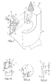
- Auger bit 30 has an elongate auger portion 32, a lead screw 34, a spur 36 (not shown in figure 2), a shearing blade 38, and a chisel blade 40.
- Auger portion 32 includes an elongate shaft 42 having a longitudinal central axis 44.
- An outer surface 46 of the elongate shaft 42 has elongate helical land 48 formed therein which extends from the lead screw 34 to the shank 50.
- Shank 50 is used to engage auger bit 30 in a tool, typically a motorized drill (not shown).
- the space between the elongate helical land 48 and the adjacent turn on the land 48 is the flute 52.
- the lead portion of flute 52 is the throat 54.
- the auger portion 32 is designed to remove the waste material from the workpiece during operation of the drill bit.
- the depth of the flute 52 can affect the ability of auger bit 30 to effectively remove the waste material during operation. Specifically, the greater depth of the flute the more easily the waste is removed. This must be balanced against the characteristic that as the depth of the flute increases the strength of the drill bit as a whole is reduced, since the amount of material in the drill bit is reduced. In addition, as adjacent turns of the elongate helical lands 48 are spaced further apart it is increasingly more difficult to keep the drill bit aligned when in use.
- Lead screw 34 is a self-feeding screw such that in use the lead screw causes the bit 30 to be urged into the workpiece.
- Lead screw 34 has a maximum diameter which is substantially less than the diameter of the auger portion 32.
- spur 36 extends slightly outwardly from the elongate helical land 48 and extends longitudinally in the direction of lead screw 34.
- the distal edge 56 of spur 36 extends further in the longitudinal direction than the chisel blade 40.
- Spur 36 defines the outside diameter of the bore hole of auger bit 30.
- Spur 36 extends outwardly from the outer surface 46 of land 48, thus the diameter inscribed by the spur is slightly larger than diameter of the elongate auger portion.
- the angle at which spur 36 is angled outwardly from the longitudinal axis 44 is between 1 ° to 2°. The slight angle allows elongate auger portion 32 to move freely through the bore hole but the angle is not so large that the drill bit becomes difficult to align. Further, the slight angle helps to reduce the drag on the wood auger bit when it is in use and it makes removal of the auger, once the hole is cut from workpiece, much easier.
- Chisel blade 40 extends outwardly from the leading edge of elongate helical land 48. Chisel blade 40 removes the material between the outside radius and lead screw 34. Preferably chisel blade 40 is removable and replaceable.
- a chisel seat 60 is formed in the lead edge of elongate helical land 48 and is shaped to receive chisel blade 40.
- Chisel seat 60 is adapted to receive chisel blade 40 such that chisel blade acts as a continuation of elongate helical land 48.
- a set screw 62 attaches the chisel blade 40 to the elongate helical land 48.
- Chisel seat 60 and set screw 62 are configured such that as auger bit 30 revolves and chisel blade 40 engages the workpiece the chisel blade is forced back into chisel seat 60 and into tight engagement with land 48.
- chisel blade 40 is shaped so that outside edge portion 61 (shown in figure 1 ) extends slightly outwardly from the elongate helical land 48 so that in use chisel blade 40 will wear rather than helical land 48.
- shearing blade 38 extends longitudinally from the helical land closest to the lead screw 34 towards the next adjacent land. Shearing blade 38 provides a cutting edge on the following portion 64 of helical land 48 proximate to the throat 54. Shearing blade 38 ensures that any residual material that may have been missed by spur 36 and chisel blade 40 is removed. It has been found that to ensure that waste material can be easily removed by drill bit 30, it is desirable to increase the depth of throat 54. The amount that the depth of the throat 54 needs to be increased will be dependent on the depth of the flute 52 and the spacing of the elongate helical lands 48. For example where adjacent turns of the helical lands 48 are relatively close together and the depth of the flute 52 is relatively shallow, the depth of the throat adjacent to the shearing blade 38 will need to be increased so that drill bit 30 does not get clogged with wood chips during use.
- shearing blade 38 and spur 36 are a removable and replaceable unitary component or blade 35.
- unitary blade 35 is attached to land 48 with a set screw 66.
- a groove or seat 68 (shown in figure 3) is formed in land 48 to receive unitary blade 35 such that in position the shearing blade 38 is generally aligned with outer surface 46 of shaft 42.
- Seat 68 and set screw 66 are configured such that as auger bit 30 revolves and the unitary blade 35 engages the workpiece it is forced back into seat 68 and into tight engagement with land 48.
- Multipurpose blade 70 includes a chisel portion 72, a spur portion 74 and a shearing portion 76. Each portion functions similar to that described above. Multipurpose blade 70 fits onto and wraps around end portion 78 of auger drill bit 80. Bit 80 is similar to that described above and only those portions which are different will be described hereafter. The remaining features are as described above and reference numerals used above will be used herein and shown on figure 7.
- Chisel portion 72 of multipurpose blade 70 when in position on bit 80, extends outwardly from the leading edge of elongate helical land 48.
- Spur portion 74 extends slightly outwardly from elongate helical land 48 and extends longitudinally in the direction of lead screw 34. The distal edge 90 of spur 74 extends further in the longitudinal direction than chisel portion 72.
- shearing portion 76 extends longitudinally from the helical land closest to the lead screw 34 towards the next adjacent turn of the land.
- End portion 78 of auger drill bit 80 has a seat 92 for receiving multipurpose blade 70 thereon.
- a set screw 94 is provided to secure multipurpose blade 70 in place.
- Seat 92 has a ledge 96 formed therein and the wrap portion 98 of multipurpose blade 70 proximate to the chisel portion 72 is adapted to sit on seat 92 and ledge 96 when multipurpose blade 70 is in position.
- Wrap portion 98 of multipurpose blade 70 is shaped such that there is a smooth transition between the spur portion 74, the shearing portion 76 and the chisel portion 72. Wrap portion 98 continues the helical shape of helical land 48. Multipurpose blade 70 is shaped such that the blade can only be positioned one way on auger bit 80 and thus minimizes the risk of a user installing the blade incorrectly.
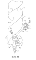
- shearing blade and spur can be used. Clearly certain designs will work better under certain conditions. By having a removable unitary shearing blade and spur, one auger bit can be used in a variety of applications. Further, when the blade wears down, as will inevitably occur with use, the blade can be easily replaced. Alternatively, by providing a blade that is removable, the blade can also be sharpened and then reattached. One such variation is shown in figure 11 wherein unitary blade 113 is reversible. Each side of the reversible blade has a shearing edge 114 and a spur edge 116. A set screw 115 is used to secure unitary blade 113 in place.
- reversible blade 113 when one side of the reversible blade 113 is dull it can simply be rotated to provide sharp cutting edges.
- a reversible chisel blade could be used so that when one side of the blade becomes dull it is reversed and the other side is used.
- other variations could also be used such as an elliptical unitary blade so that as one portion of the blade becomes dull the blade is rotated to a sharper section.
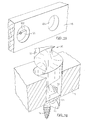
- a tapered dovetail chisel seat 128 and tapered dovetail chisel blade 130 are shown, with the tapered dovetail chisel blade 130 has chisel dovetail portions 132 that engage chisel seat dovetails 138 in the auger portion 32 of wood auger bit 136.
- Dovetail chisel seat 128 is tapered to correspond with the taper of chisel blade 130.
- Dovetail chisel seat 128 has a curved back portion 140.
- Chisel blade 130 has a straight back portion 142.
- a tapered dovetail shearing/spur seat 144 and tapered dovetail unitary blade 146 are shown, with the tapered dovetail unitary blade 146 having dovetail portions 148 that engage shearing/spur seat dovetails 150 in the auger portion 32 of the wood auger bit 136.
- Dovetail shearing/spur seat 144 is tapered to correspond with the taper of tapered dovetail unitary blade 146.
- the tapered dovetail unitary blade 146 has spur portion 154 and shearing portion 156.
- the tapered dovetail shape of the seat and blade allow the blade to be held in position by friction only, eliminating the need of fasteners and therefore increasing the ease of changing the blades in the field.
- the tapered dovetail nature of the seat is arranged so that in operation, the forces of the auger portion on the blade and vice versa would force the blade into tighter and tighter engagement with the seat.
- a force in the opposite direction, as from a punch or screwdriver is all that would be required to dislodge the blade from its tight engagement with the seat.
- the spur 120 is fixedly attached to the elongate helical land 48.
- the spur becomes dull and some users feel that when the spur is dull it is more of a hindrance than a help. Therefore it is advantageous to provide a spur 36 which is removable and replaceable as shown in the present invention.
Landscapes
- Life Sciences & Earth Sciences (AREA)
- Engineering & Computer Science (AREA)
- Mechanical Engineering (AREA)
- Wood Science & Technology (AREA)
- Forests & Forestry (AREA)
- Drilling Tools (AREA)
Applications Claiming Priority (4)
| Application Number | Priority Date | Filing Date | Title |
|---|---|---|---|
| CA2196487 | 1997-01-31 | ||
| CA 2196487 CA2196487A1 (fr) | 1996-09-19 | 1997-01-31 | Meche a bois |
| US08/917,298 US6024520A (en) | 1997-08-25 | 1997-08-25 | Auger drill bit |
| US917298 | 1997-08-25 |
Publications (2)
| Publication Number | Publication Date |
|---|---|
| EP0856387A2 true EP0856387A2 (fr) | 1998-08-05 |
| EP0856387A3 EP0856387A3 (fr) | 1999-11-03 |
Family
ID=25679022
Family Applications (1)
| Application Number | Title | Priority Date | Filing Date |
|---|---|---|---|
| EP98300691A Withdrawn EP0856387A3 (fr) | 1997-01-31 | 1998-01-30 | FÔret à mèche hélicoidale |
Country Status (1)
| Country | Link |
|---|---|
| EP (1) | EP0856387A3 (fr) |
Cited By (3)
| Publication number | Priority date | Publication date | Assignee | Title |
|---|---|---|---|---|
| USD942517S1 (en) * | 2021-02-07 | 2022-02-01 | Jun Li | Auger drill bit |
| USD943650S1 (en) * | 2021-02-05 | 2022-02-15 | Xinwei Li | Auger drill bit |
| USD944301S1 (en) * | 2021-02-07 | 2022-02-22 | Jun Li | Auger drill bit |
Family Cites Families (5)
| Publication number | Priority date | Publication date | Assignee | Title |
|---|---|---|---|---|
| US1387234A (en) * | 1920-04-06 | 1921-08-09 | Burke Andrew Jackson | Tool |
| US1493439A (en) * | 1923-02-13 | 1924-05-06 | Stephen D Steadman | Reversible spur for auger bits |
| US1557900A (en) * | 1924-09-08 | 1925-10-20 | Thomas J Holmes | Auger and bit |
| US3165131A (en) * | 1962-05-31 | 1965-01-12 | Prec Accessories Inc | Boring tool |
| GB9619622D0 (en) * | 1996-09-19 | 1996-10-30 | Haughton Tools Ltd | An auger bit |
-
1998
- 1998-01-30 EP EP98300691A patent/EP0856387A3/fr not_active Withdrawn
Cited By (3)
| Publication number | Priority date | Publication date | Assignee | Title |
|---|---|---|---|---|
| USD943650S1 (en) * | 2021-02-05 | 2022-02-15 | Xinwei Li | Auger drill bit |
| USD942517S1 (en) * | 2021-02-07 | 2022-02-01 | Jun Li | Auger drill bit |
| USD944301S1 (en) * | 2021-02-07 | 2022-02-22 | Jun Li | Auger drill bit |
Also Published As
| Publication number | Publication date |
|---|---|
| EP0856387A3 (fr) | 1999-11-03 |
Similar Documents
| Publication | Publication Date | Title |
|---|---|---|
| US6024520A (en) | Auger drill bit | |
| US4968193A (en) | Self-centering drill bit with pilot tip | |
| US5288183A (en) | Self-centering drill bit with pilot tip | |
| US7416371B2 (en) | Wood boring bit with increased speed, efficiency and ease of use | |
| US8113749B2 (en) | Auger bit including a reamer | |
| US10940545B2 (en) | Drill bit, such as an auger drill bit, and method therefore | |
| US4057357A (en) | Chipless shell cutter for large diameter plastic pipe | |
| US4480951A (en) | Self-drilling screw | |
| JP4938225B2 (ja) | 切刃と除去可能頭部とを有するナール付きファスナー | |
| EP1512476A2 (fr) | Foret à auto-centrage avec pointe pilote | |
| US7556459B2 (en) | Hole saw having a drill bit with a pilot tip | |
| US20080008548A1 (en) | Hole saw with replaceable cutting tip | |
| USRE28900E (en) | Drill bit device | |
| US6152661A (en) | Wood coring bit | |
| US3687565A (en) | Drill bit device | |
| EP0468089B1 (fr) | Vis autoperçante avec des arrêtes coupantes formant un arc curviligne vers la tête | |
| EP1924381B1 (fr) | Foret de decoupe pour outils rotatifs | |
| EP1606073B1 (fr) | Trepan en forme de pelle | |
| US20100008740A1 (en) | Rotary cutter | |
| CA2216071A1 (fr) | Meche de perceuse a tariere | |
| CA2196487A1 (fr) | Meche a bois | |
| JP3849793B2 (ja) | ドリル及びセルフドリルネジ | |
| JP2004074400A (ja) | 多段穴明け工具 | |
| US4594031A (en) | Chip extractor bushing | |
| JP3090886U (ja) | 木工用ドリル |
Legal Events
| Date | Code | Title | Description |
|---|---|---|---|
| PUAI | Public reference made under article 153(3) epc to a published international application that has entered the european phase |
Free format text: ORIGINAL CODE: 0009012 |
|
| AK | Designated contracting states |
Kind code of ref document: A2 Designated state(s): AT BE CH DE DK ES FI FR GB GR IE IT LI LU MC NL PT |
|
| AX | Request for extension of the european patent |
Free format text: AL;LT;LV;MK;RO;SI |
|
| RIN1 | Information on inventor provided before grant (corrected) |
Inventor name: HAUGHTON, GLENN WALLACE Inventor name: HAUGHTON, KEITH LOUIS |
|
| PUAL | Search report despatched |
Free format text: ORIGINAL CODE: 0009013 |
|
| AK | Designated contracting states |
Kind code of ref document: A3 Designated state(s): AT BE CH DE DK ES FI FR GB GR IE IT LI LU MC NL PT |
|
| AX | Request for extension of the european patent |
Free format text: AL;LT;LV;MK;RO;SI |
|
| AKX | Designation fees paid | ||
| REG | Reference to a national code |
Ref country code: DE Ref legal event code: 8566 |
|
| STAA | Information on the status of an ep patent application or granted ep patent |
Free format text: STATUS: THE APPLICATION IS DEEMED TO BE WITHDRAWN |
|
| 18D | Application deemed to be withdrawn |
Effective date: 20000504 |