EP0856452A2 - Colonne de direction de sécurité - Google Patents
Colonne de direction de sécurité Download PDFInfo
- Publication number
- EP0856452A2 EP0856452A2 EP97121497A EP97121497A EP0856452A2 EP 0856452 A2 EP0856452 A2 EP 0856452A2 EP 97121497 A EP97121497 A EP 97121497A EP 97121497 A EP97121497 A EP 97121497A EP 0856452 A2 EP0856452 A2 EP 0856452A2
- Authority
- EP
- European Patent Office
- Prior art keywords
- steering column
- component
- cone
- safety
- column according
- Prior art date
- Legal status (The legal status is an assumption and is not a legal conclusion. Google has not performed a legal analysis and makes no representation as to the accuracy of the status listed.)
- Granted
Links
- 239000000463 material Substances 0.000 claims description 4
- 230000003313 weakening effect Effects 0.000 claims 1
- 230000004308 accommodation Effects 0.000 abstract 1
- 241000722921 Tulipa gesneriana Species 0.000 description 2
- 230000002411 adverse Effects 0.000 description 1
- 238000005452 bending Methods 0.000 description 1
- 238000010276 construction Methods 0.000 description 1
- 230000000694 effects Effects 0.000 description 1
- 230000001788 irregular Effects 0.000 description 1
- 239000002184 metal Substances 0.000 description 1
- 238000000034 method Methods 0.000 description 1
- 230000000149 penetrating effect Effects 0.000 description 1
- 230000000717 retained effect Effects 0.000 description 1
- 238000004904 shortening Methods 0.000 description 1
Images


Classifications
-
- F—MECHANICAL ENGINEERING; LIGHTING; HEATING; WEAPONS; BLASTING
- F16—ENGINEERING ELEMENTS AND UNITS; GENERAL MEASURES FOR PRODUCING AND MAINTAINING EFFECTIVE FUNCTIONING OF MACHINES OR INSTALLATIONS; THERMAL INSULATION IN GENERAL
- F16F—SPRINGS; SHOCK-ABSORBERS; MEANS FOR DAMPING VIBRATION
- F16F7/00—Vibration-dampers; Shock-absorbers
- F16F7/12—Vibration-dampers; Shock-absorbers using plastic deformation of members
- F16F7/123—Deformation involving a bending action, e.g. strap moving through multiple rollers, folding of members
-
- B—PERFORMING OPERATIONS; TRANSPORTING
- B60—VEHICLES IN GENERAL
- B60R—VEHICLES, VEHICLE FITTINGS, OR VEHICLE PARTS, NOT OTHERWISE PROVIDED FOR
- B60R21/00—Arrangements or fittings on vehicles for protecting or preventing injuries to occupants or pedestrians in case of accidents or other traffic risks
- B60R21/02—Occupant safety arrangements or fittings, e.g. crash pads
- B60R21/04—Padded linings for the vehicle interior ; Energy absorbing structures associated with padded or non-padded linings
- B60R21/05—Padded linings for the vehicle interior ; Energy absorbing structures associated with padded or non-padded linings associated with the steering wheel, steering hand lever or steering column
-
- B—PERFORMING OPERATIONS; TRANSPORTING
- B62—LAND VEHICLES FOR TRAVELLING OTHERWISE THAN ON RAILS
- B62D—MOTOR VEHICLES; TRAILERS
- B62D1/00—Steering controls, i.e. means for initiating a change of direction of the vehicle
- B62D1/02—Steering controls, i.e. means for initiating a change of direction of the vehicle vehicle-mounted
- B62D1/04—Hand wheels
- B62D1/11—Hand wheels incorporating energy-absorbing arrangements, e.g. by being yieldable or collapsible
-
- B—PERFORMING OPERATIONS; TRANSPORTING
- B62—LAND VEHICLES FOR TRAVELLING OTHERWISE THAN ON RAILS
- B62D—MOTOR VEHICLES; TRAILERS
- B62D1/00—Steering controls, i.e. means for initiating a change of direction of the vehicle
- B62D1/02—Steering controls, i.e. means for initiating a change of direction of the vehicle vehicle-mounted
- B62D1/16—Steering columns
- B62D1/18—Steering columns yieldable or adjustable, e.g. tiltable
- B62D1/19—Steering columns yieldable or adjustable, e.g. tiltable incorporating energy-absorbing arrangements, e.g. by being yieldable or collapsible
- B62D1/192—Yieldable or collapsible columns
Definitions
- the invention relates to a safety steering column from a steering column housing with a extending into the passenger compartment and a casing rotatably mounted therein Steering shaft for holding a steering wheel, which can be shortened in the event of a frontal accident.
- Such energy absorbing safety steering columns are used to the Impact of a driver in a frontal / offset crash in addition to support dampen with an airbag.
- Security systems are known in which preformed corrugated tubes in the steering column during the crash process like an accordion are deformed and thus absorb the kinetic energy.
- the invention is based on the technical problem of an energy-absorbing one To provide safety steering column with an unrestricted The lateral stiffness of the casing tube is retained.
- a cone-like component is arranged coaxially adjacent to the end of the casing tube, whose smallest outside diameter is that of the inside diameter of the end of the Jacket tube corresponds, with this smallest outer diameter the end of Jacket tube is facing.
- the material is weakened as notches made in the edge region of the casing tube executed. These notches can be made at regular or irregular intervals be distributed over the circumference of the end of the casing tube. About a variation of the Wall thickness of the casing tube and the number and arrangement of the notches can be the behavior of the safety steering column can be expected in a wide range Adjust stresses.
- the surface of the cone-like component along a concave contour line of one small outer diameter with coaxial surface up to a large one Outside diameter with a radially extending surface.
- An embodiment of the invention is particularly advantageous in which the cone-like Component is also designed as a bearing seat for mounting the steering shaft.
- the cone-like component is non-positive and / or positive with the end of the casing tube connected.
- the cone-like component can be used as Outer shell of the steering column bearing. This leads to an essential one Reduction in the number of components required.
- this is conical Component designed as a rear component of the steering wheel, so that it is in normal operation of the Motor vehicle is rotatable relative to the casing tube and only in the case of a Head-on collision comes into contact with the casing tube.
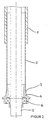
- the safety steering column consists of a steering column housing 1 with one in the Casing tube 2 extending in the passenger compartment and a steering shaft 5 rotatably mounted therein, to which the steering wheel is attached.
- a conical component 4 used with its side of the smallest outside diameter, wherein the outer diameter widens outwards until it almost reaches the end runs radially.
- the bearing 6 of the steering shaft 5 is inserted into the conical component 4.
- the casing tube 2 is pushed onto the conical component 4 and has in periodically distributed on its circumference axial notches on which the Jacket tube during a frontal accident when pushing conical component 4 and jacket tube 2 tears open in a defined manner.
- the resulting stripe-shaped Segments of the casing tube 2 are through the conical surface of the conical component 4th bent radially outward, whereby they curl-like, as shown in Figure 3 turn up or tulip up.
- Jacket tube (2) extend radially around the steering column to the outside, but none sharp sheet metal parts emerge into the passenger compartment via the contour of the steering wheel hub.
- the strength of the casing tube 2 is designed so that the steering column at a Frontal crash and ignition of the airbag are not deformed at first, but they do in the event of an impact pushes the driver together on the airbag. There is no intrusion of the Jacket tube 2 in the steering column housing and thus no collision with others Components.
Landscapes
- Engineering & Computer Science (AREA)
- Mechanical Engineering (AREA)
- Chemical & Material Sciences (AREA)
- Combustion & Propulsion (AREA)
- Transportation (AREA)
- General Engineering & Computer Science (AREA)
- Steering Controls (AREA)
- Vibration Dampers (AREA)
Applications Claiming Priority (2)
| Application Number | Priority Date | Filing Date | Title |
|---|---|---|---|
| DE19704013 | 1997-02-04 | ||
| DE19704013A DE19704013C2 (de) | 1997-02-04 | 1997-02-04 | Sicherheitslenksäule |
Publications (3)
| Publication Number | Publication Date |
|---|---|
| EP0856452A2 true EP0856452A2 (fr) | 1998-08-05 |
| EP0856452A3 EP0856452A3 (fr) | 2000-03-22 |
| EP0856452B1 EP0856452B1 (fr) | 2003-08-06 |
Family
ID=7819177
Family Applications (1)
| Application Number | Title | Priority Date | Filing Date |
|---|---|---|---|
| EP97121497A Expired - Lifetime EP0856452B1 (fr) | 1997-02-04 | 1997-12-06 | Colonne de direction de sécurité |
Country Status (7)
| Country | Link |
|---|---|
| EP (1) | EP0856452B1 (fr) |
| JP (1) | JP3242877B2 (fr) |
| KR (1) | KR100418447B1 (fr) |
| BR (1) | BR9800551A (fr) |
| DE (1) | DE19704013C2 (fr) |
| ES (1) | ES2201240T3 (fr) |
| ZA (1) | ZA98302B (fr) |
Cited By (2)
| Publication number | Priority date | Publication date | Assignee | Title |
|---|---|---|---|---|
| WO2000006439A3 (fr) * | 1998-07-24 | 2000-05-11 | Lemfoerder Lenksaeulen Gmbh | Colonne de direction de securite |
| EP1544075A4 (fr) * | 2002-06-19 | 2007-01-03 | Nsk Ltd | Dispositif pour colonne de direction de vehicule du type a absorption des chocs |
Families Citing this family (5)
| Publication number | Priority date | Publication date | Assignee | Title |
|---|---|---|---|---|
| DE10048348C2 (de) * | 2000-09-28 | 2002-11-28 | Siemens Ag | Verfahren zur Systemsynchronisation von PLC-Systemen |
| JP4529796B2 (ja) | 2005-05-26 | 2010-08-25 | アイシン精機株式会社 | 衝撃吸収式ステアリング装置 |
| JP4868213B2 (ja) | 2005-12-21 | 2012-02-01 | アイシン精機株式会社 | エネルギー吸収ステアリングコラム |
| DE102011083190A1 (de) | 2011-09-15 | 2013-03-21 | Zf Lenksysteme Nacam Gmbh | Kraftfahrzeuglenksäule mit Energieabsorber |
| DE102020205196B4 (de) | 2020-04-23 | 2022-02-17 | Volkswagen Aktiengesellschaft | Crashelement, Fahrwerksteil und Fahrzeug |
Family Cites Families (3)
| Publication number | Priority date | Publication date | Assignee | Title |
|---|---|---|---|---|
| US3916720A (en) * | 1973-05-14 | 1975-11-04 | Chrysler Corp | Energy absorbing steering column |
| DE4206781A1 (de) * | 1991-03-16 | 1992-09-17 | Volkswagen Ag | Nach dem stuelpprinzip arbeitendes deformationselement |
| DE4404569A1 (de) * | 1993-02-25 | 1994-09-01 | Volkswagen Ag | Nach dem Stülpprinzip arbeitendes Deformationselement |
-
1997
- 1997-02-04 DE DE19704013A patent/DE19704013C2/de not_active Expired - Lifetime
- 1997-12-06 EP EP97121497A patent/EP0856452B1/fr not_active Expired - Lifetime
- 1997-12-06 ES ES97121497T patent/ES2201240T3/es not_active Expired - Lifetime
- 1997-12-16 KR KR1019970069048A patent/KR100418447B1/ko not_active Expired - Fee Related
-
1998
- 1998-01-14 ZA ZA98302A patent/ZA98302B/xx unknown
- 1998-02-04 JP JP02335398A patent/JP3242877B2/ja not_active Expired - Fee Related
- 1998-02-04 BR BR9800551A patent/BR9800551A/pt not_active IP Right Cessation
Non-Patent Citations (1)
| Title |
|---|
| None |
Cited By (3)
| Publication number | Priority date | Publication date | Assignee | Title |
|---|---|---|---|---|
| WO2000006439A3 (fr) * | 1998-07-24 | 2000-05-11 | Lemfoerder Lenksaeulen Gmbh | Colonne de direction de securite |
| EP1544075A4 (fr) * | 2002-06-19 | 2007-01-03 | Nsk Ltd | Dispositif pour colonne de direction de vehicule du type a absorption des chocs |
| US7445241B2 (en) | 2002-06-19 | 2008-11-04 | Nsk Ltd. | Vehicle impact absorption type steering column device |
Also Published As
| Publication number | Publication date |
|---|---|
| ES2201240T3 (es) | 2004-03-16 |
| JP3242877B2 (ja) | 2001-12-25 |
| ZA98302B (en) | 1998-07-20 |
| EP0856452A3 (fr) | 2000-03-22 |
| MX9801026A (es) | 1998-08-30 |
| DE19704013C2 (de) | 1998-11-19 |
| EP0856452B1 (fr) | 2003-08-06 |
| KR100418447B1 (ko) | 2004-06-04 |
| DE19704013A1 (de) | 1998-08-06 |
| JPH10217980A (ja) | 1998-08-18 |
| BR9800551A (pt) | 1999-06-15 |
| KR19980070162A (ko) | 1998-10-26 |
Similar Documents
| Publication | Publication Date | Title |
|---|---|---|
| DE3833048C2 (de) | Stoßfänger für Kraftfahrzeuge, insbesondere Personenkraftwagen | |
| DE1630005C3 (de) | Sicherheitslenksäule für Kraftfahrzeuge | |
| DE1630859C (fr) | ||
| EP3938268B1 (fr) | Entraînement de réglage pour une colonne de direction et colonne de direction pour un véhicule automobile | |
| DE4240237A1 (de) | Stauchrohr | |
| DE1277685B (de) | Sicherheits lenksäule fur Kraftfahrzeuge | |
| EP1541424B1 (fr) | Un élément d'absorption de choc en form profilé creux | |
| DE19508533C2 (de) | Airbagmodul für Kraftfahrzeuge | |
| EP0572821B1 (fr) | Colonne de direction de voiture | |
| DE2422479C2 (de) | Pralldämpfer mit Kraftbegrenzung | |
| EP0856452B1 (fr) | Colonne de direction de sécurité | |
| EP0748734B1 (fr) | Colonne de direction de sécurité | |
| DE102019202297A1 (de) | Lenksäule für ein Kraftfahrzeug | |
| WO1999011501A1 (fr) | Dispositif de direction d'un vehicule | |
| EP1114754B1 (fr) | Amortisseur de choc | |
| EP1015291B1 (fr) | Colonne de direction de securite | |
| DE19833421C2 (de) | Sicherheitslenksäule für Kraftfahrzeuge | |
| DE19508443B4 (de) | Halterung für einen lenkradseitigen Lenksäulenteil | |
| EP1295777B1 (fr) | Unité de volant de direction pour véhicule automobile | |
| DE29907513U1 (de) | Als Deformationsdämpfer ausgebildeter Pralldämpfer | |
| DE19704184C2 (de) | Sicherheitslenksäule für ein Kraftfahrzeug | |
| DE102016208091A1 (de) | Baugruppe für ein Kraftfahrzeug | |
| DE19962550B4 (de) | Sicherheitsvorrichtung für ein Kraftfahrzeug | |
| DE4320640A1 (de) | Antriebsstrang für Kraftfahrzeuge mit bei einem Frontalaufprall Stoßenergie absorbierenden Verformungsbereichen | |
| DE102006014075A1 (de) | Lenksäulenanordnung für Fahrzeuge |
Legal Events
| Date | Code | Title | Description |
|---|---|---|---|
| PUAI | Public reference made under article 153(3) epc to a published international application that has entered the european phase |
Free format text: ORIGINAL CODE: 0009012 |
|
| AK | Designated contracting states |
Kind code of ref document: A2 Designated state(s): ES FR GB IT NL SE |
|
| AX | Request for extension of the european patent |
Free format text: AL;LT;LV;MK;RO;SI |
|
| PUAL | Search report despatched |
Free format text: ORIGINAL CODE: 0009013 |
|
| AK | Designated contracting states |
Kind code of ref document: A3 Designated state(s): AT BE CH DE DK ES FI FR GB GR IE IT LI LU MC NL PT SE |
|
| AX | Request for extension of the european patent |
Free format text: AL;LT;LV;MK;RO;SI |
|
| RIC1 | Information provided on ipc code assigned before grant |
Free format text: 7B 62D 1/19 A, 7F 16F 7/12 B, 7B 62D 1/11 B |
|
| 17P | Request for examination filed |
Effective date: 20000510 |
|
| AKX | Designation fees paid |
Free format text: ES FR GB IT NL SE |
|
| REG | Reference to a national code |
Ref country code: DE Ref legal event code: 8566 |
|
| 17Q | First examination report despatched |
Effective date: 20020402 |
|
| GRAH | Despatch of communication of intention to grant a patent |
Free format text: ORIGINAL CODE: EPIDOS IGRA |
|
| GRAH | Despatch of communication of intention to grant a patent |
Free format text: ORIGINAL CODE: EPIDOS IGRA |
|
| RAP1 | Party data changed (applicant data changed or rights of an application transferred) |
Owner name: ZF LEMFOERDER METALLWAREN AG |
|
| RAP1 | Party data changed (applicant data changed or rights of an application transferred) |
Owner name: NACAM DEUTSCHLAND GMBH |
|
| GRAA | (expected) grant |
Free format text: ORIGINAL CODE: 0009210 |
|
| AK | Designated contracting states |
Designated state(s): ES FR GB IT NL SE |
|
| REG | Reference to a national code |
Ref country code: GB Ref legal event code: FG4D Free format text: NOT ENGLISH |
|
| GBT | Gb: translation of ep patent filed (gb section 77(6)(a)/1977) | ||
| REG | Reference to a national code |
Ref country code: SE Ref legal event code: TRGR |
|
| REG | Reference to a national code |
Ref country code: ES Ref legal event code: FG2A Ref document number: 2201240 Country of ref document: ES Kind code of ref document: T3 |
|
| ET | Fr: translation filed | ||
| PLBE | No opposition filed within time limit |
Free format text: ORIGINAL CODE: 0009261 |
|
| STAA | Information on the status of an ep patent application or granted ep patent |
Free format text: STATUS: NO OPPOSITION FILED WITHIN TIME LIMIT |
|
| 26N | No opposition filed |
Effective date: 20040507 |
|
| PGFP | Annual fee paid to national office [announced via postgrant information from national office to epo] |
Ref country code: GB Payment date: 20051130 Year of fee payment: 9 |
|
| PGFP | Annual fee paid to national office [announced via postgrant information from national office to epo] |
Ref country code: NL Payment date: 20051204 Year of fee payment: 9 |
|
| PGFP | Annual fee paid to national office [announced via postgrant information from national office to epo] |
Ref country code: SE Payment date: 20051206 Year of fee payment: 9 |
|
| PGFP | Annual fee paid to national office [announced via postgrant information from national office to epo] |
Ref country code: FR Payment date: 20051208 Year of fee payment: 9 |
|
| PGFP | Annual fee paid to national office [announced via postgrant information from national office to epo] |
Ref country code: ES Payment date: 20060118 Year of fee payment: 9 |
|
| PG25 | Lapsed in a contracting state [announced via postgrant information from national office to epo] |
Ref country code: SE Free format text: LAPSE BECAUSE OF NON-PAYMENT OF DUE FEES Effective date: 20061207 |
|
| PGFP | Annual fee paid to national office [announced via postgrant information from national office to epo] |
Ref country code: IT Payment date: 20061231 Year of fee payment: 10 |
|
| PG25 | Lapsed in a contracting state [announced via postgrant information from national office to epo] |
Ref country code: NL Free format text: LAPSE BECAUSE OF NON-PAYMENT OF DUE FEES Effective date: 20070701 |
|
| EUG | Se: european patent has lapsed | ||
| GBPC | Gb: european patent ceased through non-payment of renewal fee |
Effective date: 20061206 |
|
| NLV4 | Nl: lapsed or anulled due to non-payment of the annual fee |
Effective date: 20070701 |
|
| REG | Reference to a national code |
Ref country code: FR Ref legal event code: ST Effective date: 20070831 |
|
| PG25 | Lapsed in a contracting state [announced via postgrant information from national office to epo] |
Ref country code: GB Free format text: LAPSE BECAUSE OF NON-PAYMENT OF DUE FEES Effective date: 20061206 |
|
| REG | Reference to a national code |
Ref country code: ES Ref legal event code: FD2A Effective date: 20061207 |
|
| PG25 | Lapsed in a contracting state [announced via postgrant information from national office to epo] |
Ref country code: FR Free format text: LAPSE BECAUSE OF NON-PAYMENT OF DUE FEES Effective date: 20070102 Ref country code: ES Free format text: LAPSE BECAUSE OF NON-PAYMENT OF DUE FEES Effective date: 20061207 |
|
| PG25 | Lapsed in a contracting state [announced via postgrant information from national office to epo] |
Ref country code: IT Free format text: LAPSE BECAUSE OF NON-PAYMENT OF DUE FEES Effective date: 20071206 |