EP0856474A1 - Bouchon à bande d'inviolabilité - Google Patents
Bouchon à bande d'inviolabilité Download PDFInfo
- Publication number
- EP0856474A1 EP0856474A1 EP98400195A EP98400195A EP0856474A1 EP 0856474 A1 EP0856474 A1 EP 0856474A1 EP 98400195 A EP98400195 A EP 98400195A EP 98400195 A EP98400195 A EP 98400195A EP 0856474 A1 EP0856474 A1 EP 0856474A1
- Authority
- EP
- European Patent Office
- Prior art keywords
- fin
- cap according
- flange
- zone
- under
- Prior art date
- Legal status (The legal status is an assumption and is not a legal conclusion. Google has not performed a legal analysis and makes no representation as to the accuracy of the status listed.)
- Withdrawn
Links
- 238000007789 sealing Methods 0.000 title description 3
- 230000014759 maintenance of location Effects 0.000 claims description 2
- 238000005452 bending Methods 0.000 description 4
- 230000002427 irreversible effect Effects 0.000 description 4
- 238000004873 anchoring Methods 0.000 description 1
- 238000009434 installation Methods 0.000 description 1
- 210000000056 organ Anatomy 0.000 description 1
- 230000002093 peripheral effect Effects 0.000 description 1
- 230000000717 retained effect Effects 0.000 description 1
- 238000000926 separation method Methods 0.000 description 1
- 238000005728 strengthening Methods 0.000 description 1
Images

Classifications
-
- B—PERFORMING OPERATIONS; TRANSPORTING
- B65—CONVEYING; PACKING; STORING; HANDLING THIN OR FILAMENTARY MATERIAL
- B65D—CONTAINERS FOR STORAGE OR TRANSPORT OF ARTICLES OR MATERIALS, e.g. BAGS, BARRELS, BOTTLES, BOXES, CANS, CARTONS, CRATES, DRUMS, JARS, TANKS, HOPPERS, FORWARDING CONTAINERS; ACCESSORIES, CLOSURES, OR FITTINGS THEREFOR; PACKAGING ELEMENTS; PACKAGES
- B65D41/00—Caps, e.g. crown caps or crown seals, i.e. members having parts arranged for engagement with the external periphery of a neck or wall defining a pouring opening or discharge aperture; Protective cap-like covers for closure members, e.g. decorative covers of metal foil or paper
- B65D41/32—Caps or cap-like covers with lines of weakness, tearing-strips, tags, or like opening or removal devices, e.g. to facilitate formation of pouring openings
- B65D41/34—Threaded or like caps or cap-like covers provided with tamper elements formed in, or attached to, the closure skirt
- B65D41/3423—Threaded or like caps or cap-like covers provided with tamper elements formed in, or attached to, the closure skirt with flexible tabs, or elements rotated from a non-engaging to an engaging position, formed on the tamper element or in the closure skirt
- B65D41/3428—Threaded or like caps or cap-like covers provided with tamper elements formed in, or attached to, the closure skirt with flexible tabs, or elements rotated from a non-engaging to an engaging position, formed on the tamper element or in the closure skirt the tamper element being integrally connected to the closure by means of bridges
Definitions
- the present invention relates to a tamper-evident band cap.
- a threaded plug intended to close off a container whose neck is provided with a hanging flange.
- the lower zone is generally provided with a peripheral internal projection or fins which are liable to deform elastically. During the initial installation of the cap on the container these projections or fins can therefore retract when the flange passes before locking by pressing their free end under said flange.
- the flexibility of the fins is such that sometimes the blockage is not not irreversible.
- the cap when the cap is first unscrewed, the tamper-evident band is stressing and some fins can then deform before even the breakable area is not broken.
- the present invention aims to solve this technical problem of satisfactorily by seeking an irreversible locking of the fin under the container flange.
- a plug threaded for closing a container the neck of which is provided with a hooking collar comprising a tamper-evident band consisting of an upper zone breakable for attachment to the cap body and a lower zone provided with at least one locking fin under said flange, characterized in that said fin has a first support zone against the underside of said flange and a second support zone against the side wall of the container neck located under said collar so as to ensure the retention of the lower zone of the strip under the collar by bracing of the fin.
- said first and / or second support zones consist of surfaces carried by the projecting ends of the fin.
- the first and second support zones of the fin are carried by two separate teeth formed on the ends protruding from the fin.
- said fin has a cross section polygonal; said first and second support zones being formed by the edges of the end polygon.
- said first and second support zones consist of contact lines located on the protruding ends of the fin.
- the plane passing through the first and second support zones is inclined relative to the axis of the plug with an angle between 0 and 90 ° and preferably equal to 45 °.
- the wall of the tamper-evident band has a thickness more significant in the area under said fin.
- the lower edge of the tamper-evident band has a heel capable of abutting against a shoulder made on the container neck and below said collar.
- the section of the fin is increasing from the zone of connection with the strip to its end carrying the two support zones with a factor between 3 and 4.
- the mean inclination of the fin relative to the axis of the cap is preferably between 35 ° and 40 °.
- the plug of the present invention provides a lock reliable and irreversible of the tamper-evident band under the collar.
- the double support forming the bracing of the fins on the neck of the container ensures a hooking whose resistance increases with the intensity of the lifting force produced by the unscrewing.
- the first and second support zones tend to move away from each other thereby strengthening anchoring under the flange.
- the tamper-evident band while ensuring a hooking reinforced by double support of the fins has a softness and flexibility sufficient to allow easy initial mounting of the cap on the neck of the container after filling or bottling.
- the cap shown in FIG. 1 comprises a body 1 provided with a internal thread 10, intended to be screwed onto the threaded neck of a container fitted with a hooking collar, in order to seal it tightly.
- the bottom of the cap is here provided with a seal J which can possibly be replaced by a self-sealing lip or any other organ sealing.
- This cap also includes a tamper-evident band 2 made up a breakable upper zone 20 for attachment to the body 1 of the plug and a lower locking area under the flange of the container.
- the lower zone is provided, on the periphery of its internal face with a projecting element consisting of several fins 21 produced in a discontinuous manner, as in the embodiment shown here or in another embodiment of realization (not shown) in the form of a single continuous fin.
- the fins have an axial rigidity which avoids any risk of crushing.
- these fins 21 are made with an elastically material deformable and can therefore pivot and / or flex upwards around an axis which is perpendicular to the axis of the plug and which passes through the connection zone 22 between the fin 21 and the internal face of the strip 2.
- This pivoting and / or deformation capacity allows the fins 21 to retract when they come into forced support contact from above on the flange, in the initial assembly phase of the cap on the container.
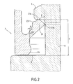
- the fins 21 can be deployed at new in the space included, under the collar, between the internal face of the strip 2 and the outer wall of the container neck as shown in FIG. 2.
- the fins 21 are therefore in the locked position. irreversible under the flange C of the container R.
- Each fin 21 has a first support zone 21a against the underside of the flange C and a second support zone 21b against the wall lateral external side of the neck of the container R, under the flange C.
- the lower zone of the strip 2 is thus retained downwards by bracing of fin 21.
- the body 1 of the plug tends to mount on the container neck while the lower zone of the strip 2 is held down by the fins 21, which causes the breakable zone 20 to rupture.
- the double support of the fin 21 respectively under the flange and on the side wall of the collar ensures firm and resistant attachment.
- the fin 21 has here a polygonal cross section, the first 21a and second 21b support zones of the fin 21 being formed by the edges of the end polygon.
- the first support zone 21a against the underside of the flange C is a curved surface carried by the projecting upper end of the fin 21.
- the second support zone 21b against the side wall of the neck is here angular and is carried by the projecting lower end of said fin.
- the first and second support zones of the fin are carried by two separate teeth on the projecting ends, and then consist of simple contact lines.
- the fin 21 has an increasing section from the connection zone 22 to its projecting ends forming the support zones 21a, 21b.
- the relationship between end section and the section of the connection zone 22 with the strip 2 is between 3 and 4.
- the mean inclination of the fin 21 relative to the axis of the plug is between 35 ° and 40 °. This average inclination is determined from the inclinations ⁇ , ⁇ respectively of the lower and upper faces of the fin 21 relative to the axis of the plug.
- the plane passing through the first zone at the same time support 21a and by the second support area 21b of the fin 21 is inclined relative to to the axis of the plug with an angle between 0 and 90 ° and preferably equal at 45 °.
- the upper face of the fin 21 is provided with a boss 23 intended to limit pivoting and / or upward bending of the fin.
- This boss 23 thus forms a stop which comes into contact with the face internal of the strip 2, above the connection zone 22 by bending of the fin, when passing the flange C.
- the lower edge of the strip 2 has at least at the level of the fins 21, an enlarged section forming a heel 24.
- the heel 24 extends upwards by a straight flank to the connecting zone 22. Under these conditions the wall of the strip 2 located under the fin has a greater thickness than the wall located above of said fin, which prohibits any bending and / or pivoting of the fin 21 down.
- the container R has a shoulder E located under the flange C. This shoulder is made at a distance d from the flange C such that the heel 24 can abut towards the low against said shoulder, when the cap is unscrewed, when the fin 21 is energized by the double press described above.
Landscapes
- Engineering & Computer Science (AREA)
- Mechanical Engineering (AREA)
- Closures For Containers (AREA)
Abstract
Description
Claims (10)
- Bouchon fileté destiné à obturer un récipient (R) dont le col est pourvu d'une collerette (C) d'accrochage comprenant une bande d'inviolabilité (2) constituée d'une zone sécable (20) de rattachement au corps (1) du bouchon et d'une zone inférieure pourvue d'au moins une ailette (21) de verrouillage sous ladite collerette (C), caractérisé en que ladite ailette (21) comporte une première zone d'appui (21a) contre la face inférieure de ladite collerette (C) et une seconde zone d'appui (21b) contre la paroi latérale du col du récipient (R) située sous ladite collerette (C) de façon à assurer la retenue de la zone inférieure de la bande (2) sous la collerette (C) par arc-boutement de l'ailette (21).
- Bouchon selon la revendication 1, caractérisé en ce que lesdites première et/ou seconde zones d'appui (21a, 21b) sont constituées de surfaces portées par les extrémités saillantes de l'ailette (21).
- Bouchon selon la revendication 1 ou 2, caractérisé en ce que les première et seconde zones d'appui (21a, 21b) de l'ailette (21) sont portées par deux dents distinctes ménagées sur les extrémités saillantes de l'ailette (21).
- Bouchon selon l'une des revendications précédentes, caractérisé en ce que ladite ailette (21) possède une section transversale polygonale, lesdites première et seconde zones d'appui (21a, 21b) étant formées par les arêtes du polygone d'extrémité.
- Bouchon selon l'une des revendications 1 à 3, caractérisé en ce que lesdites première et seconde zones d'appui (21a, 21b) sont constituées de lignes de contact situées sur les extrémités saillantes de l'ailette (21).
- Bouchon selon l'une des revendications précédentes, caractérisé en ce que le plan passant par les première et seconde zones d'appui (21a, 21b) est incliné par rapport à l'axe du bouchon avec un angle (γ) compris entre 0 et 90° et de préférence égal à 45°.
- Bouchon selon l'une des revendications précédentes, caractérisé en ce que la paroi de la bande d'inviolabilité (2) a une épaisseur plus importante dans la zone située sous ladite ailette (21).
- Bouchon selon l'une des revendications précédentes, caractérisé en ce que le bord inférieur de la bande d'inviolabilité (2) possède un talon (24) susceptible de venir en appui contre un épaulement (E) réalisé sur le col du récipient (R) en dessous de ladite collerette (C).
- Bouchon selon l'une des revendications précédentes, caractérisé en ce que la section de l'ailette (21) est croissante depuis la zone de liaison (22) avec la bande jusqu'à son extrémité portant les deux zones d'appui (21a, 21b) avec un facteur compris entre 3 et 4.
- Bouchon selon l'une des revendications précédentes, caractérisé en ce que l'inclinaison moyenne de l'ailette (21) par rapport à l'axe du bouchon est comprise entre 35° et 40°.
Applications Claiming Priority (2)
| Application Number | Priority Date | Filing Date | Title |
|---|---|---|---|
| LU90016 | 1997-01-31 | ||
| LU90016A LU90016B1 (fr) | 1997-01-31 | 1997-01-31 | Bouchon à bande d'inviolabilité |
Publications (1)
| Publication Number | Publication Date |
|---|---|
| EP0856474A1 true EP0856474A1 (fr) | 1998-08-05 |
Family
ID=19731657
Family Applications (1)
| Application Number | Title | Priority Date | Filing Date |
|---|---|---|---|
| EP98400195A Withdrawn EP0856474A1 (fr) | 1997-01-31 | 1998-01-30 | Bouchon à bande d'inviolabilité |
Country Status (2)
| Country | Link |
|---|---|
| EP (1) | EP0856474A1 (fr) |
| LU (1) | LU90016B1 (fr) |
Cited By (3)
| Publication number | Priority date | Publication date | Assignee | Title |
|---|---|---|---|---|
| EP1683732A1 (fr) * | 2005-01-19 | 2006-07-26 | Rieke Corporation | Bande d'inviolabilité pour fermeture de flacon |
| WO2017061001A1 (fr) * | 2015-10-08 | 2017-04-13 | 日本山村硝子株式会社 | Capuchon en résine synthétique |
| CN112055689A (zh) * | 2018-03-01 | 2020-12-08 | 安德烈·卢洽娜·马丁斯 | 用于带有密封元件的容器的自动开启装置 |
Families Citing this family (2)
| Publication number | Priority date | Publication date | Assignee | Title |
|---|---|---|---|---|
| GR1003064B (el) * | 1997-07-22 | 1999-02-04 | Bruno Zumbuhl | Επιρραματικη κατασκευη για πωματα που διαθετουν ενδεικτικους δακτυλιους παραποιησης |
| WO2000034133A2 (fr) * | 1998-12-07 | 2000-06-15 | Tjandra Limanjaya | Capsule de fermeture |
Citations (6)
| Publication number | Priority date | Publication date | Assignee | Title |
|---|---|---|---|---|
| DE3905017A1 (de) * | 1989-02-18 | 1990-08-23 | Wilhelm Goetz | Verschluss fuer flaschen und dergleichen behaelter |
| US5107998A (en) * | 1991-06-14 | 1992-04-28 | Bruno Zumbuhl | Tamper proof ring for threaded closures |
| US5145078A (en) * | 1990-06-14 | 1992-09-08 | Charles Hannon | Pilfer-proof bottle cap |
| EP0508396A1 (fr) * | 1991-04-09 | 1992-10-14 | H-C Industries, Inc. | Fermeture de garantie en matière plastique |
| WO1996024532A1 (fr) * | 1995-02-10 | 1996-08-15 | Crown Cork Ag | Bouchon a bande d'inviolabilite |
| WO1997000209A1 (fr) * | 1995-06-14 | 1997-01-03 | Bruno Zumbuhl | Bouchon filete pour des recipients a surpression interne |
-
1997
- 1997-01-31 LU LU90016A patent/LU90016B1/fr active
-
1998
- 1998-01-30 EP EP98400195A patent/EP0856474A1/fr not_active Withdrawn
Patent Citations (6)
| Publication number | Priority date | Publication date | Assignee | Title |
|---|---|---|---|---|
| DE3905017A1 (de) * | 1989-02-18 | 1990-08-23 | Wilhelm Goetz | Verschluss fuer flaschen und dergleichen behaelter |
| US5145078A (en) * | 1990-06-14 | 1992-09-08 | Charles Hannon | Pilfer-proof bottle cap |
| EP0508396A1 (fr) * | 1991-04-09 | 1992-10-14 | H-C Industries, Inc. | Fermeture de garantie en matière plastique |
| US5107998A (en) * | 1991-06-14 | 1992-04-28 | Bruno Zumbuhl | Tamper proof ring for threaded closures |
| WO1996024532A1 (fr) * | 1995-02-10 | 1996-08-15 | Crown Cork Ag | Bouchon a bande d'inviolabilite |
| WO1997000209A1 (fr) * | 1995-06-14 | 1997-01-03 | Bruno Zumbuhl | Bouchon filete pour des recipients a surpression interne |
Cited By (4)
| Publication number | Priority date | Publication date | Assignee | Title |
|---|---|---|---|---|
| EP1683732A1 (fr) * | 2005-01-19 | 2006-07-26 | Rieke Corporation | Bande d'inviolabilité pour fermeture de flacon |
| US7575123B2 (en) | 2005-01-19 | 2009-08-18 | Rieke Corporation | Tamper-evident locking band for a container closure |
| WO2017061001A1 (fr) * | 2015-10-08 | 2017-04-13 | 日本山村硝子株式会社 | Capuchon en résine synthétique |
| CN112055689A (zh) * | 2018-03-01 | 2020-12-08 | 安德烈·卢洽娜·马丁斯 | 用于带有密封元件的容器的自动开启装置 |
Also Published As
| Publication number | Publication date |
|---|---|
| LU90016B1 (fr) | 1997-06-13 |
Similar Documents
| Publication | Publication Date | Title |
|---|---|---|
| EP3741703B1 (fr) | Bouchon à vis destiné à rester attaché a un récipient après ouverture du récipient | |
| EP0682625A1 (fr) | Dispositif de bouchage pour recipient | |
| FR2820120A1 (fr) | Bouchon avec orifice verseur ferme par un couvercle et systeme d'inviolabilite du couvercle | |
| EP3393924B1 (fr) | Système d'obturation pour récipient | |
| FR3094353A1 (fr) | Dispositif de bouchage destine a etre fixe sur un col d’un recipient | |
| EP0644125A1 (fr) | Bouchon | |
| CA2353719A1 (fr) | Capsule de bouchage pour un recipient a collerette d'accrochage | |
| FR3096361A1 (fr) | Bouchon à vis destiné à rester attaché à un récipient après ouverture du récipient. | |
| EP4026783B1 (fr) | Dispositif de bouchage destiné à être fixé sur le col d'un récipient | |
| EP4026785B1 (fr) | Dispositif de bouchage comprenant un bouchon articulé sur une base | |
| LU88845A1 (fr) | Conditionnement pour produits liquides et en particulier pour produits alimentaires | |
| FR2835811A1 (fr) | Insert fonctionnel pour goulot de recipient, typiquement une bouteille, et capsule de bouchage comprenant ledit insert | |
| EP2014567A1 (fr) | Bouchon encliquetable pourvu d'une lèvre d'étanchéité | |
| EP3984906B1 (fr) | Bouchon à vis destiné à rester attaché à un récipient après ouverture et pouvant être maintenu dans une position d´ ouverture | |
| EP1007429B1 (fr) | Fermeture encliquetable pour un fut a biere | |
| WO2003011699A1 (fr) | Bouchon comprenant une jupe interieure d'etancheite | |
| EP0937653A1 (fr) | Système de bouchage d'une ouverture d'un récipient | |
| EP1219873B1 (fr) | Clapet à joint serti et procédé de fabrication d'un tel clapet | |
| FR2779702A1 (fr) | Dispositif de bouchage a vis de type inviolable | |
| FR2937624A1 (fr) | Bouchon a obturateur coulissant | |
| EP4005945A1 (fr) | Ensemble comprenant un récipient et un dispositif de bouchage attaché au récipient | |
| FR2736893A1 (fr) | Bouchon en matiere plastique monobloc et ensemble comprenant un tel bouchon et un recipient | |
| EP1311439B1 (fr) | Bouchon comportant des moyens de blocage de la deformation radiale de la bague d'inviolabilite | |
| BE897445A (fr) | Flacon equipe d'un capot de bouchage etanche | |
| CA2981936A1 (fr) | Bouchon pour un col de recipient |
Legal Events
| Date | Code | Title | Description |
|---|---|---|---|
| PUAI | Public reference made under article 153(3) epc to a published international application that has entered the european phase |
Free format text: ORIGINAL CODE: 0009012 |
|
| AK | Designated contracting states |
Kind code of ref document: A1 Designated state(s): AT BE CH DE DK ES FI FR GB GR IE IT LI LU MC NL PT SE |
|
| AX | Request for extension of the european patent |
Free format text: AL;LT;LV;MK;RO;SI |
|
| 17P | Request for examination filed |
Effective date: 19990201 |
|
| AKX | Designation fees paid |
Free format text: AT BE CH DE DK ES FI FR GB GR IE IT LI LU MC NL PT SE |
|
| AXX | Extension fees paid |
Free format text: LT PAYMENT 19990201;LV PAYMENT 19990201;RO PAYMENT 19990201;SI PAYMENT 19990201 |
|
| RBV | Designated contracting states (corrected) |
Designated state(s): AT BE CH DE DK ES FI FR GB GR IE IT LI LU MC NL PT SE |
|
| RAP1 | Party data changed (applicant data changed or rights of an application transferred) |
Owner name: L&M SERVICES B.V. |
|
| 17Q | First examination report despatched |
Effective date: 20020531 |
|
| STAA | Information on the status of an ep patent application or granted ep patent |
Free format text: STATUS: THE APPLICATION IS DEEMED TO BE WITHDRAWN |
|
| 18D | Application deemed to be withdrawn |
Effective date: 20021211 |