EP0856639A2 - Abgasturbine eines Turboladers - Google Patents
Abgasturbine eines Turboladers Download PDFInfo
- Publication number
- EP0856639A2 EP0856639A2 EP98810023A EP98810023A EP0856639A2 EP 0856639 A2 EP0856639 A2 EP 0856639A2 EP 98810023 A EP98810023 A EP 98810023A EP 98810023 A EP98810023 A EP 98810023A EP 0856639 A2 EP0856639 A2 EP 0856639A2
- Authority
- EP
- European Patent Office
- Prior art keywords
- turbine
- exhaust gas
- housing
- seal
- nozzle ring
- Prior art date
- Legal status (The legal status is an assumption and is not a legal conclusion. Google has not performed a legal analysis and makes no representation as to the accuracy of the status listed.)
- Withdrawn
Links
- 239000007789 gas Substances 0.000 claims description 60
- PXHVJJICTQNCMI-UHFFFAOYSA-N Nickel Chemical compound [Ni] PXHVJJICTQNCMI-UHFFFAOYSA-N 0.000 claims description 7
- 238000002485 combustion reaction Methods 0.000 claims description 5
- 229910000831 Steel Inorganic materials 0.000 claims description 4
- 229910052759 nickel Inorganic materials 0.000 claims description 4
- 239000010959 steel Substances 0.000 claims description 4
- VYZAMTAEIAYCRO-UHFFFAOYSA-N Chromium Chemical compound [Cr] VYZAMTAEIAYCRO-UHFFFAOYSA-N 0.000 claims description 3
- 239000003779 heat-resistant material Substances 0.000 claims description 3
- 238000011144 upstream manufacturing Methods 0.000 claims 1
- 238000007789 sealing Methods 0.000 description 18
- 239000000463 material Substances 0.000 description 3
- 238000005192 partition Methods 0.000 description 2
- 230000036316 preload Effects 0.000 description 2
- 230000015572 biosynthetic process Effects 0.000 description 1
- 230000003247 decreasing effect Effects 0.000 description 1
- 239000012530 fluid Substances 0.000 description 1
- 230000007704 transition Effects 0.000 description 1
Images

Classifications
-
- F—MECHANICAL ENGINEERING; LIGHTING; HEATING; WEAPONS; BLASTING
- F01—MACHINES OR ENGINES IN GENERAL; ENGINE PLANTS IN GENERAL; STEAM ENGINES
- F01D—NON-POSITIVE DISPLACEMENT MACHINES OR ENGINES, e.g. STEAM TURBINES
- F01D9/00—Stators
- F01D9/02—Nozzles; Nozzle boxes; Stator blades; Guide conduits, e.g. individual nozzles
- F01D9/04—Nozzles; Nozzle boxes; Stator blades; Guide conduits, e.g. individual nozzles forming ring or sector
- F01D9/048—Nozzles; Nozzle boxes; Stator blades; Guide conduits, e.g. individual nozzles forming ring or sector for radial admission
-
- F—MECHANICAL ENGINEERING; LIGHTING; HEATING; WEAPONS; BLASTING
- F01—MACHINES OR ENGINES IN GENERAL; ENGINE PLANTS IN GENERAL; STEAM ENGINES
- F01D—NON-POSITIVE DISPLACEMENT MACHINES OR ENGINES, e.g. STEAM TURBINES
- F01D11/00—Preventing or minimising internal leakage of working-fluid, e.g. between stages
- F01D11/005—Sealing means between non relatively rotating elements
- F01D11/006—Sealing the gap between rotor blades or blades and rotor
-
- F—MECHANICAL ENGINEERING; LIGHTING; HEATING; WEAPONS; BLASTING
- F01—MACHINES OR ENGINES IN GENERAL; ENGINE PLANTS IN GENERAL; STEAM ENGINES
- F01D—NON-POSITIVE DISPLACEMENT MACHINES OR ENGINES, e.g. STEAM TURBINES
- F01D9/00—Stators
- F01D9/02—Nozzles; Nozzle boxes; Stator blades; Guide conduits, e.g. individual nozzles
- F01D9/04—Nozzles; Nozzle boxes; Stator blades; Guide conduits, e.g. individual nozzles forming ring or sector
- F01D9/045—Nozzles; Nozzle boxes; Stator blades; Guide conduits, e.g. individual nozzles forming ring or sector for radial flow machines or engines
-
- F—MECHANICAL ENGINEERING; LIGHTING; HEATING; WEAPONS; BLASTING
- F05—INDEXING SCHEMES RELATING TO ENGINES OR PUMPS IN VARIOUS SUBCLASSES OF CLASSES F01-F04
- F05D—INDEXING SCHEME FOR ASPECTS RELATING TO NON-POSITIVE-DISPLACEMENT MACHINES OR ENGINES, GAS-TURBINES OR JET-PROPULSION PLANTS
- F05D2220/00—Application
- F05D2220/40—Application in turbochargers
Definitions
- the invention relates to the exhaust gas turbine of a turbocharger, with one in the inflow duct arranged the exhaust gas turbine, the working medium on the turbine blades conductive nozzle ring.
- the nozzle rings of the exhaust gas turbines of turbochargers are changed by Operating conditions, i.e. Increase or decrease in pressure and temperature of the working medium, highly stressed. Depending on the used Turbine and according to the specific conditions of use, the working medium have a large temperature gradient. Because a nozzle ring opposite the turbine components surrounding it always have a low mass possesses, it is subject to relatively strong temperature expansions.
- the nozzle ring is often attached by simply jamming it in the Exhaust turbine housing. Since the nozzle ring does not change accordingly in this case can expand, material warping and cracks occur, so that such a nozzle ring does not have a sufficient lifespan. So he has to be exchanged in relatively short time intervals, which in addition to additional Cost also results in a loss of turbine work.
- the invention tries to avoid all of these disadvantages. You have the task to create a nozzle ring for the exhaust gas turbine of a turbocharger, which in addition to an improved service life also a constant efficiency guaranteed.
- a radial expansion gap is formed between the turbine housing and the nozzle ring and at least in this expansion gap a seal is arranged.
- the nozzle ring consists of two in the recess arranged fasteners, which over a number are connected to each other by guide vanes. Either in at least one of the Fasteners or in at least one of the fasteners surrounding components of the turbine housing is a seal receiving circumferential groove formed.
- the seal is designed as a lamellar ring.
- One out of one is particularly advantageous sufficient heat-resistant material, such as chrome nickel steel existing double lamellar ring.
- Such a seal encloses you 720 ° angle. It can not only withstand high temperatures of up to 750 ° C Resist undamaged but also provides an improved seal of the expansion gap. This can further increase turbine efficiency and the service life of the nozzle ring can also be increased.
- the seal is also made of a sufficiently heat-resistant Made of existing piston ring material. This is another possibility given to seal the expansion gap, which according to the concrete operating conditions is available.
- an embodiment of the invention is based on a Radial turbine of a turbocharger shown.
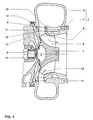
- the exhaust gas turbocharger mainly consists of a compressor, not shown and an exhaust gas turbine designed as a radial turbine 1.
- the radial turbine 1 has a turbine housing 2, with a spiral gas inlet housing 3, a gas outlet housing 4 designed as a gas outlet flange and a Intermediate wall, turbine-side housing component 5.
- a turbine wheel 7 In the turbine housing 2 is a turbine wheel 7 with rotor blades carried by a shaft 6 8 rotatably mounted. There is also no compressor on shaft 6 shown compressor wheel arranged.
- the gas inlet housing 3 goes downstream into an inflow duct 9 for the exhaust gases 10 a connected to the exhaust gas turbocharger, also not shown Internal combustion engine over.
- a nozzle ring 11 is form-fitting in the inflow channel 9 between the gas inlet housing 3 and the gas outlet flange 4 and the intermediate wall 5 arranged.
- the shaft 6 is by means of bearings 12 in a bearing housing 13 rotatably mounted.
- the gas inlet housing 3 and the bearing housing 13 are connected to one another via a tensioning band 14 arranged in the circumferential direction.
- the gas outlet flange 4 and the gas inlet housing 3 are by screws 15 releasably attached to each other (Fig. 1).
- the nozzle ring 11 consists of two annular fastening elements 16, 17, which are connected to one another via a number of guide vanes 18.
- the turbine housing 2 for Receiving the nozzle ring 11 has the turbine housing 2 in the region of the transition from the gas inlet housing 3 to the gas outlet flange 4 or to the intermediate wall 5 a recess 19.
- a radial expansion gap 20 is formed, which is both the axial and the radial expansion of the nozzle ring 11 allowed.
- Gas inlet side of the nozzle ring 11 is in the fastener 17 a circumferential groove 21 is arranged and in the flow direction of the exhaust gases 10 aligned.
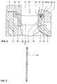
- the groove 21 takes a double lamellar ring, i.e. seal 22 enclosing an angle of 720 °.
- the double slat ring 22 is made of chrome-nickel steel, although of course other heat-resistant ones Materials can be used.
- Both in the groove 21 and in the recess 19 of the turbine housing 2 is a sealing surface 23, 24 for each Double lamellar ring 22 arranged (Fig. 2).
- a simple one or a triple slat ring can be used.
- Figure 3 is a longitudinal section through the indicated in Figure and also only partially shown double lamellar ring 22 shown. For the sake of clarity an enlarged view was chosen.
- exhaust gases 10 first enter the spiral Gas inlet housing 3 of the radial turbine 1. Be in the gas inlet housing 3 it accelerates and via the nozzle ring 11 with an optimal flow angle passed to the turbine wheel 7. There the exhaust gases 10 are finally expanded. They give a power, which drives the shaft 6 and so that the compressor wheel serves.
- the nozzle ring can 11 Expand freely in both the axial and radial directions. Doing so the exhaust gas pressure acting via the inflow duct 9 and the expansion gap 20 the double lamellar ring 22 always on the sealing surface 23 of the groove 21. Accordingly an extensive sealing of the expansion gap 20 is achieved. At Corresponding test bench tests were able to achieve efficiency gains of up to three points compared to variants without sealing the expansion gap 20 be determined.
- the circumferential groove 21 is in the Gas outlet flange 4 formed (Fig. 4).
- This is a second variant of the arrangement given the seal 22, which with appropriate design requirements is used.
- a second sealing surface 23 arranged in the groove 21 Sealing surface 27 is formed on the fastening element 17 of the nozzle ring 11.
- the function of this double lamellar ring 22 is analogous to the first exemplary embodiment.
- the circumferential groove 21 can also be in the fastening element 16 or in the partition 5, i.e. also gas inlet or gas outlet side of the Nozzle ring 11 are formed (not shown).
- a piston ring is designed in a third exemplary embodiment Seal 28 on the gas inlet side of the nozzle ring 11, between its fastening element 17 and the gas inlet housing 3.
- the piston ring 28 is received by a correspondingly adapted groove 29.
- a sealing surface 30, 31 for the piston ring 28 is arranged.
- To ensure a good seal To ensure a piston ring 28 is used with a hooked impact (not shown). All other components of the radial turbine 1 are analogous to the first Embodiment formed.
- the function of the piston ring 28 corresponds the function of the double lamellar ring 22.
Landscapes
- Engineering & Computer Science (AREA)
- Mechanical Engineering (AREA)
- General Engineering & Computer Science (AREA)
- Supercharger (AREA)
Abstract
Description
- Fig. 1
- einen Teillängsschnitt der Radialturbine;
- Fig. 2
- einen vergrösserten Ausschnitt von Fig. 1, im Bereich des Düsenrings;
- Fig. 3
- einen Längsschnitt durch die erfindungsgemässe Dichtung, entsprechend Fig. 1, jedoch vergrössert dargestellt;
- Fig. 4
- eine Darstellung entsprechend Fig. 2, jedoch in einem zweiten Ausführungsbeispiel;
- Fig. 5
- eine Darstellung entsprechend Fig. 2, jedoch in einem dritten Ausführungsbeispiel.
- 1
- Abgasturbine, Radialturbine
- 2
- Turbinengehäuse
- 3
- Gaseintrittgehäuse
- 4
- Gasaustrittgehäuse, Gasaustrittflansch
- 5
- turbinenseitiger Gehäusebauteil, Zwischenwand
- 6
- Welle
- 7
- Turbinenrad
- 8
- Laufschaufel
- 9
- Einströmkanal
- 10
- Abgas
- 11
- Düsenring
- 12
- Lager
- 13
- Lagergehäuse
- 14
- Spannband
- 15
- Schraube
- 16
- Befestigungselement
- 17
- Befestigungselement
- 18
- Leitschaufel
- 19
- Ausnehmung
- 20
- Dehnungsspalt
- 21
- Nut
- 22
- Dichtung, Doppel-Lamellenring
- 23
- Dichtfläche, von 21
- 24
- Dichtfläche, von 19
- 25
- Aussendurchmesser
- 26
- Abschrägung
- 27
- Dichtfläche, von 17
- 28
- Dichtung, Kolbenring
- 29
- Nut
- 30
- Dichtfläche, von 29
- 31
- Dichtfläche, von 19
Claims (10)
- Abgasturbine eines Turboladers, mit einem aus einem Gaseintrittgehäuse (3), einem Gasaustrittgehäuse (4) sowie zumindest einem turbinenseitigen Gehäusebauteil (5) bestehenden Turbinengehäuse (2), einem auf einer Welle (6) drehbar gelagerten Turbinenrad (7) mit Laufschaufeln (8), einem im Turbinengehäuse (2), stromauf des Turbinenrades (7) ausgebildeten Einströmkanal (9) für die Abgase (10) einer mit dem Turbolader verbundenen Brennkraftmaschine sowie mit einem im Einströmkanal (9) angeordneten, in einer Ausnehmung (19) des Turbinengehäuses (2) befestigten, die Abgase (10) auf die Laufschaufeln (8) leitenden Düsenring (11), dadurch gekennzeichnet, dass zwischen dem Turbinengehäuse (2) und dem Düsenring (11) ein radialer Dehnungsspalt (20) ausgebildet und im Dehnungsspalt (20) zumindest eine Dichtung (22, 28) angeordnet ist.
- Abgasturbine nach Anspruch 1, dadurch gekennzeichnet, dass der Düsenring (11) aus zwei in der Ausnehmung (19) angeordneten Befestigungselementen (16, 17) besteht, welche über eine Anzahl von Leitschaufeln (18) miteinander verbunden sind und entweder in zumindest einem der Befestigungselemente (16, 17) oder in zumindest einem der die Befestigungselemente (16, 17) umgebenden Bauteile (3, 4, 5) des Turbinengehäuses (2) eine die Dichtung (22, 28) aufnehmende, umlaufende Nut (21) ausgebildet ist.
- Abgasturbine nach Anspruch 2, dadurch gekennzeichnet, dass die umlaufende Nut (21) in Strömungsrichtung der Abgase (10) ausgerichtet ist.
- Abgasturbine nach Anspruch 3, dadurch gekennzeichnet, dass die Dichtung (22, 28) zwischen dem Gaseintrittgehäuse (3) und dem Düsenring (11) angeordnet ist.
- Abgasturbine nach Anspruch 3, dadurch gekennzeichnet, dass die Dichtung (22, 28) zwischen dem turbinenseitigen Gehäusebauteil (5) und dem Düsenring (11) angeordnet ist.
- Abgasturbine nach Anspruch 3, dadurch gekennzeichnet, dass die Dichtung (22, 28) zwischen dem Gasaustrittgehäuse (4) und dem Düsenring (11) angeordnet ist.
- Abgasturbine nach einem der Ansprüche 4 bis 6, dadurch gekennzeichnet, dass die Dichtung (22) als Lamellenring, insbesondere als Doppel-Lamellenring, ausgebildet ist.
- Abgasturbine nach Anspruch 7, dadurch gekennzeichnet, dass der Lamellenring (22) aus einem ausreichend hitzebeständigen Werkstoff, insbesondere aus Chromnickelstahl besteht.
- Abgasturbine nach einem der Ansprüche 4 bis 6, dadurch gekennzeichnet, dass die Dichtung (28) als Kolbenring ausgebildet ist.
- Abgasturbine nach Anspruch 9, dadurch gekennzeichnet, dass der Kolbenring (28) aus einem ausreichend hitzebeständigen Werkstoff, insbesondere aus Chromnickelstahl besteht.
Applications Claiming Priority (2)
| Application Number | Priority Date | Filing Date | Title |
|---|---|---|---|
| DE19703033A DE19703033A1 (de) | 1997-01-29 | 1997-01-29 | Abgasturbine eines Turboladers |
| DE19703033 | 1997-01-29 |
Publications (2)
| Publication Number | Publication Date |
|---|---|
| EP0856639A2 true EP0856639A2 (de) | 1998-08-05 |
| EP0856639A3 EP0856639A3 (de) | 2000-04-19 |
Family
ID=7818574
Family Applications (1)
| Application Number | Title | Priority Date | Filing Date |
|---|---|---|---|
| EP98810023A Withdrawn EP0856639A3 (de) | 1997-01-29 | 1998-01-20 | Abgasturbine eines Turboladers |
Country Status (7)
| Country | Link |
|---|---|
| US (1) | US5964574A (de) |
| EP (1) | EP0856639A3 (de) |
| JP (1) | JP3004616B2 (de) |
| KR (1) | KR19980070758A (de) |
| CN (1) | CN1192513A (de) |
| CZ (1) | CZ292035B6 (de) |
| DE (1) | DE19703033A1 (de) |
Cited By (2)
| Publication number | Priority date | Publication date | Assignee | Title |
|---|---|---|---|---|
| US7384236B2 (en) | 2002-12-02 | 2008-06-10 | Abb Turbo Systems Ag | Exhaust-gas-turbine casing |
| EP3929407A1 (de) * | 2020-06-23 | 2021-12-29 | ABB Schweiz AG | Modularer düsenring für eine turbinenstufe einer strömungsmaschine |
Families Citing this family (53)
| Publication number | Priority date | Publication date | Assignee | Title |
|---|---|---|---|---|
| US6565468B2 (en) | 1999-12-21 | 2003-05-20 | The Gates Corporation | Tensioner with damping mechanism |
| JP4370662B2 (ja) * | 2000-03-17 | 2009-11-25 | アイシン精機株式会社 | 可変容量ターボチャージャ |
| US6287091B1 (en) * | 2000-05-10 | 2001-09-11 | General Motors Corporation | Turbocharger with nozzle ring coupling |
| EP1180632A1 (de) * | 2000-08-07 | 2002-02-20 | ABB Turbo Systems AG | Axiales Sicherungssystem |
| DE10051223A1 (de) | 2000-10-16 | 2002-04-25 | Alstom Switzerland Ltd | Verbindbare Statorelemente |
| JP2003184563A (ja) * | 2001-12-14 | 2003-07-03 | Aisin Seiki Co Ltd | 可変容量ターボチャージャ |
| EP1394363B1 (de) * | 2002-08-26 | 2006-03-01 | BorgWarner Inc. | Verstellbares Leitgitter für eine Turbineneinheit |
| EP1536103B1 (de) | 2003-11-28 | 2013-09-04 | BorgWarner, Inc. | Strömungsmaschine mit Leitgitter und Befestigungseinrichtung dafür |
| JP4729901B2 (ja) * | 2004-11-01 | 2011-07-20 | 株式会社Ihi | 過給機および密封装置 |
| US8047772B2 (en) * | 2005-03-30 | 2011-11-01 | Honeywell International Inc. | Variable geometry turbine for a turbocharger and method of controlling the turbine |
| US8152489B2 (en) * | 2006-08-18 | 2012-04-10 | Ihi Corporation | Motor-driven supercharger |
| US7559199B2 (en) | 2006-09-22 | 2009-07-14 | Honeywell International Inc. | Variable-nozzle cartridge for a turbocharger |
| JP5045304B2 (ja) * | 2007-08-16 | 2012-10-10 | 株式会社Ihi | ターボチャージャ |
| JP4952558B2 (ja) * | 2007-12-12 | 2012-06-13 | 株式会社Ihi | ターボチャージャ |
| JP2009197633A (ja) * | 2008-02-20 | 2009-09-03 | Ihi Corp | ターボチャージャ |
| DE102008057878A1 (de) * | 2008-11-18 | 2010-05-20 | Bosch Mahle Turbo Systems Gmbh & Co. Kg | Ladeeinrichtung |
| JP5402061B2 (ja) * | 2009-02-17 | 2014-01-29 | 株式会社Ihi | ターボチャージャ |
| JP5402682B2 (ja) * | 2010-01-29 | 2014-01-29 | 株式会社Ihi | ターボチャージャのシール装置 |
| US8857178B2 (en) * | 2011-06-28 | 2014-10-14 | Caterpillar Inc. | Nozzled turbocharger turbine and associated engine and method |
| DE112012003266T5 (de) * | 2011-09-27 | 2014-05-22 | Borgwarner Inc. | Halbdurchlässiges Medium zur Abdichtung einer Betätigungswelle |
| JP5710452B2 (ja) * | 2011-11-16 | 2015-04-30 | トヨタ自動車株式会社 | ターボチャージャ |
| IN2014DN08616A (de) * | 2012-03-30 | 2015-05-22 | Borgwarner Inc | |
| JP5949164B2 (ja) * | 2012-05-29 | 2016-07-06 | 株式会社Ihi | 可変ノズルユニット及び可変容量型過給機 |
| JP6051791B2 (ja) * | 2012-11-06 | 2016-12-27 | トヨタ自動車株式会社 | ターボチャージャ |
| EP2733311B1 (de) * | 2012-11-16 | 2019-01-02 | ABB Turbo Systems AG | Düsenring |
| JP6331423B2 (ja) * | 2014-01-29 | 2018-05-30 | 株式会社Ihi | 可変容量型過給機 |
| JP6542246B2 (ja) * | 2014-10-02 | 2019-07-10 | 株式会社Ihi | 可変容量型過給機 |
| CN104564174B (zh) * | 2014-12-29 | 2017-01-18 | 北京华清燃气轮机与煤气化联合循环工程技术有限公司 | 一种燃气轮机透平静叶弹性密封结构 |
| US9810238B2 (en) | 2015-03-09 | 2017-11-07 | Caterpillar Inc. | Turbocharger with turbine shroud |
| US10066639B2 (en) | 2015-03-09 | 2018-09-04 | Caterpillar Inc. | Compressor assembly having a vaneless space |
| US9752536B2 (en) | 2015-03-09 | 2017-09-05 | Caterpillar Inc. | Turbocharger and method |
| US10006341B2 (en) | 2015-03-09 | 2018-06-26 | Caterpillar Inc. | Compressor assembly having a diffuser ring with tabs |
| US9777747B2 (en) | 2015-03-09 | 2017-10-03 | Caterpillar Inc. | Turbocharger with dual-use mounting holes |
| US9915172B2 (en) | 2015-03-09 | 2018-03-13 | Caterpillar Inc. | Turbocharger with bearing piloted compressor wheel |
| US9650913B2 (en) | 2015-03-09 | 2017-05-16 | Caterpillar Inc. | Turbocharger turbine containment structure |
| US9638138B2 (en) | 2015-03-09 | 2017-05-02 | Caterpillar Inc. | Turbocharger and method |
| US9822700B2 (en) | 2015-03-09 | 2017-11-21 | Caterpillar Inc. | Turbocharger with oil containment arrangement |
| US9903225B2 (en) | 2015-03-09 | 2018-02-27 | Caterpillar Inc. | Turbocharger with low carbon steel shaft |
| US9890788B2 (en) | 2015-03-09 | 2018-02-13 | Caterpillar Inc. | Turbocharger and method |
| US9683520B2 (en) | 2015-03-09 | 2017-06-20 | Caterpillar Inc. | Turbocharger and method |
| US9739238B2 (en) | 2015-03-09 | 2017-08-22 | Caterpillar Inc. | Turbocharger and method |
| US9732633B2 (en) | 2015-03-09 | 2017-08-15 | Caterpillar Inc. | Turbocharger turbine assembly |
| US9879594B2 (en) | 2015-03-09 | 2018-01-30 | Caterpillar Inc. | Turbocharger turbine nozzle and containment structure |
| CN106337697B (zh) * | 2016-09-13 | 2019-02-01 | 中国北方发动机研究所(天津) | 一种喷嘴环密封结构 |
| US10731546B2 (en) * | 2017-02-06 | 2020-08-04 | Borgwarner Inc. | Diffuser in wastegate turbine housings |
| DE102017114397A1 (de) * | 2017-06-28 | 2019-01-03 | 2G Energy AG | Verfahren zur Anpassung eines Turboladers sowie eines Stationärmotorsystems sowie Turbolader und Stationärmotorsystem |
| WO2019044777A1 (ja) * | 2017-08-28 | 2019-03-07 | 株式会社豊田自動織機 | ターボチャージャ |
| DE102017127628A1 (de) * | 2017-11-22 | 2019-05-23 | Man Energy Solutions Se | Turbine und Turbolader |
| US10612418B2 (en) * | 2018-03-22 | 2020-04-07 | GM Global Technology Operations LLC | Nested flange joint |
| KR20240161676A (ko) | 2022-03-22 | 2024-11-12 | 터보 시스템즈 스위츠랜드 엘티디. | 레이디얼 터빈용 노즐 링, 배기 터빈, 및 터보차저 |
| CN119053772A (zh) * | 2022-05-25 | 2024-11-29 | 株式会社Ihi | 涡轮机以及增压器 |
| JP7841974B2 (ja) * | 2022-07-13 | 2026-04-07 | 本田技研工業株式会社 | ガスタービン及びラジアルタービンノズルの組付方法 |
| DE102022118731A1 (de) | 2022-07-26 | 2024-02-01 | Rolls-Royce Solutions GmbH | Turbinenanordnungen, Turbolader und Brennkraftmaschine |
Citations (1)
| Publication number | Priority date | Publication date | Assignee | Title |
|---|---|---|---|---|
| EP0024275A1 (de) | 1979-08-15 | 1981-03-04 | BBC Aktiengesellschaft Brown, Boveri & Cie. | Arretierung von Düsenringen |
Family Cites Families (16)
| Publication number | Priority date | Publication date | Assignee | Title |
|---|---|---|---|---|
| DE111098C (de) * | ||||
| US1154777A (en) * | 1914-02-21 | 1915-09-28 | Gen Electric | Attaching means for nozzles. |
| US1922017A (en) * | 1931-10-27 | 1933-08-08 | Gen Electric | Elastic fluid turbine |
| FR994013A (fr) * | 1944-12-05 | 1951-11-09 | Rateau Soc | Perfectionnement à l'exécution des distributeurs et tuyères de turbines |
| US2668006A (en) * | 1949-11-08 | 1954-02-02 | Baldwin Lima Hamilton Corp | Turbocharger |
| US3068638A (en) * | 1953-06-09 | 1962-12-18 | Laval Steam Turbine Inc De | Turbocharger for internal com. bustion engines |
| DE1040569B (de) * | 1954-07-08 | 1958-10-09 | Westinghouse Electric Corp | Befestigung der Duesensegmente im Gehaeuse einer Dampfturbine |
| US3737247A (en) * | 1971-04-12 | 1973-06-05 | Garrett Corp | Composite nozzle |
| JPS5257410A (en) * | 1975-11-07 | 1977-05-11 | Hitachi Ltd | Leakage sealing mechanism for axial fluid machine |
| US4242040A (en) * | 1979-03-21 | 1980-12-30 | Rotoflow Corporation | Thrust adjusting means for nozzle clamp ring |
| US4311432A (en) * | 1979-11-20 | 1982-01-19 | United Technologies Corporation | Radial seal |
| US4687412A (en) * | 1985-07-03 | 1987-08-18 | Pratt & Whitney Canada Inc. | Impeller shroud |
| DE3541508C1 (de) * | 1985-11-23 | 1987-02-05 | Kuehnle Kopp Kausch Ag | Abgasturbolader |
| US4679984A (en) * | 1985-12-11 | 1987-07-14 | The Garrett Corporation | Actuation system for variable nozzle turbine |
| GB2234295B (en) * | 1989-07-21 | 1993-07-21 | Rolls Royce Plc | Gas turbine engine compressor assembly |
| US5249920A (en) * | 1992-07-09 | 1993-10-05 | General Electric Company | Turbine nozzle seal arrangement |
-
1997
- 1997-01-29 DE DE19703033A patent/DE19703033A1/de not_active Withdrawn
-
1998
- 1998-01-20 EP EP98810023A patent/EP0856639A3/de not_active Withdrawn
- 1998-01-22 US US09/012,035 patent/US5964574A/en not_active Expired - Lifetime
- 1998-01-23 KR KR1019980002038A patent/KR19980070758A/ko not_active Ceased
- 1998-01-27 CN CN98105958A patent/CN1192513A/zh active Pending
- 1998-01-27 JP JP10013696A patent/JP3004616B2/ja not_active Expired - Fee Related
- 1998-01-28 CZ CZ1998263A patent/CZ292035B6/cs not_active IP Right Cessation
Patent Citations (1)
| Publication number | Priority date | Publication date | Assignee | Title |
|---|---|---|---|---|
| EP0024275A1 (de) | 1979-08-15 | 1981-03-04 | BBC Aktiengesellschaft Brown, Boveri & Cie. | Arretierung von Düsenringen |
Cited By (4)
| Publication number | Priority date | Publication date | Assignee | Title |
|---|---|---|---|---|
| US7384236B2 (en) | 2002-12-02 | 2008-06-10 | Abb Turbo Systems Ag | Exhaust-gas-turbine casing |
| US7946809B2 (en) | 2002-12-02 | 2011-05-24 | Abb Turbo Systems Ag | Exhaust-gas-turbine casing |
| EP3929407A1 (de) * | 2020-06-23 | 2021-12-29 | ABB Schweiz AG | Modularer düsenring für eine turbinenstufe einer strömungsmaschine |
| WO2021259862A1 (de) * | 2020-06-23 | 2021-12-30 | Abb Switzerland Ltd. | Modularer düsenring für eine turbinenstufe einer strömungsmaschine |
Also Published As
| Publication number | Publication date |
|---|---|
| CZ292035B6 (cs) | 2003-07-16 |
| JP3004616B2 (ja) | 2000-01-31 |
| EP0856639A3 (de) | 2000-04-19 |
| CN1192513A (zh) | 1998-09-09 |
| CZ26398A3 (cs) | 1998-08-12 |
| US5964574A (en) | 1999-10-12 |
| JPH10220235A (ja) | 1998-08-18 |
| KR19980070758A (ko) | 1998-10-26 |
| DE19703033A1 (de) | 1998-07-30 |
Similar Documents
| Publication | Publication Date | Title |
|---|---|---|
| DE19703033A1 (de) | Abgasturbine eines Turboladers | |
| EP0806548B1 (de) | Abgasturbine eines Abgasturboladers | |
| EP1664489B1 (de) | Gasturbine mit einem ringförmigen dichtungsmittel | |
| DE60222324T2 (de) | Befestigung von metallischen Aufsätzen auf CMC-Turbomaschinenbrennkammerwänden | |
| DE69804010T2 (de) | Dichtungseinrichtung für den abdeckring einer gasturbine | |
| DE60318792T2 (de) | Zapfluft-Gehäuse für einen Verdichter | |
| DE69404827T2 (de) | Befestigungssystem für keramische blätter | |
| DE69812052T2 (de) | Turbinenmantelring | |
| DE69114051T2 (de) | Verbesserungen an Ummantelungen von Turbinenrotoren. | |
| DE2819808C1 (de) | Leitschaufelkranz fuer die Turbine eines Gasturbinentriebwerks | |
| DE19821889B4 (de) | Verfahren und Vorrichtung zur Durchführung von Reparatur- und/oder Wartungsarbeiten im Innengehäuse einer mehrschaligen Turbomaschine | |
| DE60113796T2 (de) | Statorschaufel-Struktur einer Gasturbine | |
| DE2624312A1 (de) | Turbine, insbesondere fuer einen turbolader | |
| DE102007029004A1 (de) | Abgasturbolader für eine Brennkraftmaschine | |
| EP0806547B1 (de) | Axialturbine eines Abgasturboladers | |
| DE2907749A1 (de) | Einrichtung zur minimierung und konstanthaltung der bei axialturbinen vorhandenen schaufelspitzenspiele, insbesondere fuer gasturbinentriebwerke | |
| EP0999349B1 (de) | Axialturbine | |
| DE10238658A1 (de) | Verdichter, insbesondere in einem Abgasturbolader für eine Brennkraftmaschine | |
| DE2920193A1 (de) | Kuehlluftzufuehrungsanordnung fuer ein gasturbinentriebwerk | |
| DE102007048274A1 (de) | Abgasturbolader | |
| DE2532554C2 (de) | Verdichterstator | |
| DE2140337C3 (de) | Gasturbinentriebwerk mit wärmebeweglich gelagerter Welle | |
| DE3210218C2 (de) | ||
| DE2929046A1 (de) | Stroemungsmitteldichtung mit reibberuehrung | |
| EP3763917A1 (de) | Leitschaufelsegment mit stützabschnittsrippe |
Legal Events
| Date | Code | Title | Description |
|---|---|---|---|
| PUAI | Public reference made under article 153(3) epc to a published international application that has entered the european phase |
Free format text: ORIGINAL CODE: 0009012 |
|
| AK | Designated contracting states |
Kind code of ref document: A2 Designated state(s): DE GB |
|
| AX | Request for extension of the european patent |
Free format text: AL;LT;LV;MK;RO;SI |
|
| PUAL | Search report despatched |
Free format text: ORIGINAL CODE: 0009013 |
|
| AK | Designated contracting states |
Kind code of ref document: A3 Designated state(s): AT BE CH DE DK ES FI FR GB GR IE IT LI LU MC NL PT SE |
|
| AX | Request for extension of the european patent |
Free format text: AL;LT;LV;MK;RO;SI |
|
| RIC1 | Information provided on ipc code assigned before grant |
Free format text: 7F 01D 9/04 A, 7F 01D 11/00 B, 7F 01D 25/24 B |
|
| RAP1 | Party data changed (applicant data changed or rights of an application transferred) |
Owner name: ABB TURBO SYSTEMS AG |
|
| 17P | Request for examination filed |
Effective date: 20000913 |
|
| AKX | Designation fees paid |
Free format text: DE GB |
|
| 17Q | First examination report despatched |
Effective date: 20021028 |
|
| GRAP | Despatch of communication of intention to grant a patent |
Free format text: ORIGINAL CODE: EPIDOSNIGR1 |
|
| STAA | Information on the status of an ep patent application or granted ep patent |
Free format text: STATUS: THE APPLICATION IS DEEMED TO BE WITHDRAWN |
|
| 18D | Application deemed to be withdrawn |
Effective date: 20040130 |