EP0856661A2 - Brennstoffpumpe - Google Patents
Brennstoffpumpe Download PDFInfo
- Publication number
- EP0856661A2 EP0856661A2 EP97308047A EP97308047A EP0856661A2 EP 0856661 A2 EP0856661 A2 EP 0856661A2 EP 97308047 A EP97308047 A EP 97308047A EP 97308047 A EP97308047 A EP 97308047A EP 0856661 A2 EP0856661 A2 EP 0856661A2
- Authority
- EP
- European Patent Office
- Prior art keywords
- pump
- fuel
- dead centre
- pump plunger
- plunger
- Prior art date
- Legal status (The legal status is an assumption and is not a legal conclusion. Google has not performed a legal analysis and makes no representation as to the accuracy of the status listed.)
- Withdrawn
Links
- 239000000446 fuel Substances 0.000 title claims abstract description 90
- 238000002347 injection Methods 0.000 claims abstract description 27
- 239000007924 injection Substances 0.000 claims abstract description 27
- 230000008878 coupling Effects 0.000 claims abstract description 26
- 238000010168 coupling process Methods 0.000 claims abstract description 26
- 238000005859 coupling reaction Methods 0.000 claims abstract description 26
- 238000002485 combustion reaction Methods 0.000 claims abstract description 4
- 238000005086 pumping Methods 0.000 claims description 28
- 230000000295 complement effect Effects 0.000 claims description 5
- 230000009471 action Effects 0.000 claims description 3
- 230000004044 response Effects 0.000 claims description 3
- 238000012423 maintenance Methods 0.000 claims description 2
- 230000001419 dependent effect Effects 0.000 claims 3
- 239000010687 lubricating oil Substances 0.000 description 4
- 239000003921 oil Substances 0.000 description 3
- 230000000712 assembly Effects 0.000 description 2
- 238000000429 assembly Methods 0.000 description 2
- 230000008901 benefit Effects 0.000 description 2
- 230000000694 effects Effects 0.000 description 2
- 230000007246 mechanism Effects 0.000 description 2
- 230000002301 combined effect Effects 0.000 description 1
- 238000005553 drilling Methods 0.000 description 1
- 239000012530 fluid Substances 0.000 description 1
- 238000009434 installation Methods 0.000 description 1
- 239000000314 lubricant Substances 0.000 description 1
- 230000002093 peripheral effect Effects 0.000 description 1
- 230000009467 reduction Effects 0.000 description 1
- 230000001105 regulatory effect Effects 0.000 description 1
- 238000005096 rolling process Methods 0.000 description 1
- 238000007789 sealing Methods 0.000 description 1
Images

Classifications
-
- F—MECHANICAL ENGINEERING; LIGHTING; HEATING; WEAPONS; BLASTING
- F04—POSITIVE - DISPLACEMENT MACHINES FOR LIQUIDS; PUMPS FOR LIQUIDS OR ELASTIC FLUIDS
- F04B—POSITIVE-DISPLACEMENT MACHINES FOR LIQUIDS; PUMPS
- F04B49/00—Control, e.g. of pump delivery, or pump pressure of, or safety measures for, machines, pumps, or pumping installations, not otherwise provided for, or of interest apart from, groups F04B1/00 - F04B47/00
- F04B49/06—Control using electricity
-
- F—MECHANICAL ENGINEERING; LIGHTING; HEATING; WEAPONS; BLASTING
- F04—POSITIVE - DISPLACEMENT MACHINES FOR LIQUIDS; PUMPS FOR LIQUIDS OR ELASTIC FLUIDS
- F04B—POSITIVE-DISPLACEMENT MACHINES FOR LIQUIDS; PUMPS
- F04B1/00—Multi-cylinder machines or pumps characterised by number or arrangement of cylinders
- F04B1/02—Multi-cylinder machines or pumps characterised by number or arrangement of cylinders having two cylinders
-
- F—MECHANICAL ENGINEERING; LIGHTING; HEATING; WEAPONS; BLASTING
- F04—POSITIVE - DISPLACEMENT MACHINES FOR LIQUIDS; PUMPS FOR LIQUIDS OR ELASTIC FLUIDS
- F04B—POSITIVE-DISPLACEMENT MACHINES FOR LIQUIDS; PUMPS
- F04B49/00—Control, e.g. of pump delivery, or pump pressure of, or safety measures for, machines, pumps, or pumping installations, not otherwise provided for, or of interest apart from, groups F04B1/00 - F04B47/00
- F04B49/08—Regulating by delivery pressure
-
- F—MECHANICAL ENGINEERING; LIGHTING; HEATING; WEAPONS; BLASTING
- F04—POSITIVE - DISPLACEMENT MACHINES FOR LIQUIDS; PUMPS FOR LIQUIDS OR ELASTIC FLUIDS
- F04B—POSITIVE-DISPLACEMENT MACHINES FOR LIQUIDS; PUMPS
- F04B9/00—Piston machines or pumps characterised by the driving or driven means to or from their working members
- F04B9/02—Piston machines or pumps characterised by the driving or driven means to or from their working members the means being mechanical
- F04B9/04—Piston machines or pumps characterised by the driving or driven means to or from their working members the means being mechanical the means being cams, eccentrics or pin-and-slot mechanisms
- F04B9/042—Piston machines or pumps characterised by the driving or driven means to or from their working members the means being mechanical the means being cams, eccentrics or pin-and-slot mechanisms the means being cams
Definitions
- This invention relates to a fuel pump, and more particularly to a fuel pump for delivering high pressure fuel to a fuel injection system of an internal combustion engine.
- the preferred embodiment of the present invention is particularly suitable for supplying high pressure fuel to an accumulator or directly to the common rail of a common rail fuel injection system, but the invention is not limited to this application.
- a discharge valve prevents reverse flow of the fuel and a vacuum is created within the pumping cylinder until the fill passage is again uncovered by the pump plunger whereupon fuel may flow into the cylinder under the combined influences of the feed pressure in the fill passage and the vacuum created by the previous plunger movement.
- this design offers the advantage of a very small dead volume, it does suffer from the disadvantage of requiring a substantial force to move the plunger from its top dead centre (tdc) position to its bdc position because of plunger inertia and the vacuum which is created within the pumping cylinder during such movement.
- a spring is used to move the plunger from tdc to bdc.
- this spring limits the design of the pump, and in particular, limits the ability of the designer to increase the stroke of the pump plunger to increase the output of the pump. This is because it is not possible to engineer a spring which can provide sufficient force, stroke and velocity characteristics at high engine speeds if the stroke of the pump plunger is too long.
- the preferred embodiment of the present invention overcomes the limitation referred to above by providing an alternative means of moving the pump plunger from the tdc to the bdc position, thereby allowing a longer stroke to be achieved at high engine speed than has previously been possible.
- the use of a long stroke enables a high delivery volume to be achieved for a relatively small plunger diameter.
- Reduction in plunger diameter is desirable since it reduces the force and hence the bearing loads necessary to drive the pump plunger and, by reducing the peripheral sealing area between the plunger and its associated cylinder, reduces leakage of fuel past the plunger.
- a fuel pump comprises first and second pump plungers slidably mounted in respective first and second cylinders to define respective first and second pumping chambers; first drive means for driving the first pump plunger from a bottom dead centre position to a top dead centre position to deliver fuel from the first pumping chamber; second drive means for driving the second pump plunger from a bottom dead centre position to a top dead centre position to deliver fuel from the second pumping chamber; and coupling means mechanically coupling the first pump plunger to the second drive means and the second pump plunger to the first drive means whereby when the first pump plunger is driven by the first drive means from bottom dead centre to top dead centre the second pump plunger is driven by the coupling means from top dead centre to bottom dead centre and as the second pump plunger is driven from bottom dead centre to top dead centre by the second drive means the first pump plunger is driven from top dead centre to bottom dead centre by the coupling means.
- the coupling means comprises a rocker arm pivotally mounted on a shaft secured to the body of the pump.
- each pump plunger includes a head one side of which is acted on by the associated drive means to drive the pump plunger from bdc to tdc and the other side of which acts on the rocker arm as the plunger moves from bdc to tdc.
- a slipper member is interposed between the said other side of the head and the rocker arm to accommodate movement of the rocker arm laterally of the axis of the pump plunger as the pump plunger reciprocates.
- the slipper member has a flat face in engagement with the said other side of the pump plunger and a spherical seat which engages a complementary spherical surface of the rocker arm.
- the drive means each comprise a cam driven tappet.
- a second slipper member is interposed between each tappet and the said one side of its associated pump plunger.
- the said one side of the pump plunger is spherical in the zone where it is engaged by the second slipper member, and the second slipper member has a spherical surface complementary to that of the said one side of the pump plunger head.
- the respective drive means have respective cam members mounted axially displaced from each other on a common drive shaft.
- the profiles of the respective cams are such that as each pump plunger is driven from bdc to tdc the tappet of the other pump plunger is maintained in or very close to sliding contact with its associated cam by the action of the coupling means.
- the position of the coupling means is adjustable to eliminate significant backlash between the various mechanical components of the pump plunger drive system.
- the coupling means is in the form of a rocker arm
- the rocker shaft is preferably mounted by means of an eccentric on the pump body so that rotation of the rocker shaft is effective to adjust the position of the rocker arm to eliminate backlash.
- each pumping chamber has associated therewith an electrically controlled discharge valve which may be held open for a selectively variable portion of each return (i.e. tdc to bdc) stroke of its associated pump plunger.
- the volumetric output of the pump may be regulated without the need to vary the stroke of the pump plungers or spill high pressure fuel from the pump delivery to reservoir.
- a fuel injection system for an internal combustion engine comprises a fuel pump, a common rail to which high pressure fuel is delivered by the pump, a plurality of injection valves; a fuel injection nozzle associated with each fuel injection valve, the fuel injection nozzles requiring a pre-determined minimum rail pressure to open; and a safety valve fluidically connected to the common rail, the safety valve having a predetermined opening pressure and a predetermined closure pressure less than the opening pressure, the predetermined closing pressure being below the minimum rail pressure required to open the fuel injection nozzles.
- the safety valve is incorporated within a fuel injection pump.
- the fuel injection pump includes a flow restriction device which limits the rate of flow of fuel from the common rail or accumulator supplied by the pump in response to opening of the safety valve or the controlled maintenance of an open state of the discharge valves.
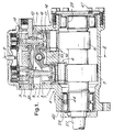
- the fuel injection pump of the preferred embodiment comprises a first pump plunger 1 and a second pump plunger 11.
- the pump plungers 1,11 are slidably mounted in respect of the first and second cylinders 2,12 to define respective first and second pumping chambers 3,13.
- the first pump plunger 1 is at a bdc position and accordingly the volume of its associated pumping chamber 3 is at a maximum, whilst the second pump plunger 11 is at a tdc position so that the volume of its associated pumping chamber 13 is at a minimum.
- a first drive means 4 is provided for driving the first pump plunger from its bdc to its tdc positions.
- a second drive means 14 is provided for driving the second pump plunger from its bdc to its tdc position.
- the first drive means comprises a cam 5 and a tappet assembly 6 comprising a tappet shell 7 which is slidably mounted in a guide bore 8 provided in the body 9 of the pump.
- the second drive means 14 comprises a cam 15 and tappet assembly 16 comprising a tappet shell 17 mounted in a bore 18 in the body 9.
- the first and second drive means are substantially identical and for the purposes of further description only the components of the second drive means will be referred to. It is to be understood, however, that the corresponding components of the first drive means are substantially identical to those which we described in relation to the second drive means.
- the second drive means 14 includes a roller 19 which is rotatably mounted on a pin 20 which is secured to the tappet shell 17.
- An appropriate bearing 21 is interposed between the pin 20 and the roller 19.
- the roller 19 is in rolling engagement with the surface of the cam 15.
- a first slipper member 22 has a flat lower surface 23 which slidingly engages a flat shoulder 24 provided on the tappet shell.
- the external diameter of the slipper member 22 is somewhat less than the internal diameter of the tappet shell at that point whereby some lateral movement of the slipper member relative to the tappet shell can be accommodated.
- the upper surface of the slipper member 22 is part-spherical and mates with a corresponding part-spherical lower surface of a head 26 which is formed integrally with the second pump plunger 11.
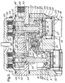
- the cams 5,15 are identical and are mounted on a common shaft 27 which is itself mounted in the body 9 by bearings 28,29. As best seen in Figure 2 the cams 5,15 are each three lobe cams. The cams 5,15 are rotationally out of register with each other by 120°. This particular arrangement of cams provides a total of six pumping strokes per revolution of the shaft 27. It is to be understood, however, that the invention is not limited to this arrangement and that other cam profiles may be used as appropriate.
- coupling means 30 are provided for coupling the first pump plunger 1 to the second drive means 14 and for coupling the second pump plunger 11 to the first drive means 4.
- the coupling means comprise a rocker arm 31 mounted on a shaft 32 which is itself secured to the body 9.
- the rocker arm 31 has end regions 33 each of which define a part-spherical thrust surface 34 and an aperture 35 through which a respective one of the pump plungers extends.
- the thrust surfaces 34 are each part-spherical and mate with corresponding part-spherical seats 36 provided on slipper members 37 each of which has a flat lower surface 38 which is in sliding contact with a flat upper surface 39 of a respective one of the heads 26.
- cam form tolerances usually mean that some lift-off will inevitably occur during some part of the motion, but this is only a small fraction of a millimetre. It will further be appreciated that the entire mechanism is preferably adjusted so that there is no more than the necessary working clearances between the various components - i.e. so there is no backlash in the drive system.
- the rocker shaft 32 is somewhat eccentric relative to the mounting holes 40 in which it is mounted in the body 9. Accordingly, by rotating the rocker shaft 32 the pivot axis of the rocker arm 31 may be moved upwardly and downwardly through a small range.
- a grub screw 41 is provided for locking the rocker shaft 32 in its adjusted position. It will be noted that this means of adjustment of the rocker shaft will produce some lateral movement of the pivot axis of the rocker arm 31 as the vertical position of the pivot axis is adjusted. However, this lateral movement will be accommodated by lateral sliding movement of the slipper members 37 on the upper surface 39 of the respective heads 26.
- a passage 44 connects the oil feed to the front bearing 28 and a passage 45 connects the oil feed 42 to the external surface of the rocker shaft 32.
- Drillings 46 provided in the rocker arm carry lubricant to various sliding surfaces of the slipper members and tappet assemblies.
- a suitable return passage for lubricating oil, for example via an outlet 47 in the pump body is provided for returning lubricating oil to the associated engine sump.
- Fuel to be pumped is supplied, for example, from a transfer pump, to a fuel inlet 48 which is connected to a gallery 49 which surrounds the cylinder members 50 which define the cylinders 2,12.
- Each cylinder member 50 includes a multiplicity of radially extending bores 51 which connect the gallery 49 to the associated cylinder 2,12.
- the radial bores 51 are positioned so that, during the majority of the stroke of the associated pump plunger, the inner ends of the radial bore are covered by the body of the pump plunger.
- the inner ends of the bores 51 are exposed to the pumping chambers 3,13 only when the corresponding pump plunger is at or near its bdc position.
- An annular groove 52 is formed in each cylinder member 50 slightly below the radial bores 51.
- the annular grooves 52 are connected to a low pressure fuel return passage 53 so that any fuel escaping from the pumping chambers 3,13 past the pump plungers 1,11 will be directed to the fuel return passage 53 rather than entering the interior of the pump where it would become mixed with lubricating oil.
- Each pumping chamber 3,13 has, at the upper end thereof (as viewed in Figure 3) a valve member 54 which is normally biassed into engagement with the upper surface of the adjacent cylinder member 50 by a light spring 55.
- a valve member 54 which is normally biassed into engagement with the upper surface of the adjacent cylinder member 50 by a light spring 55.
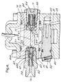
- Each valve member 54 will be lifted by fuel discharged from the pumping cylinder to allow the fuel to flow via transfer passages 56 to an outlet gallery 57 ( Figure 4).
- Each valve member 54 has associated therewith an electro-magnet 58 which, when energised, is capable of holding its associated valve member 54 away from the adjacent cylinder member 50 - i.e. is capable of holding the delivery valve open.
- the electro-magnets are selectively energised by appropriate control means to control the delivery flow from the pump. More particularly, at the end of each delivery stroke of each pump plunger the associated electro-magnet 58 is energised to hold the delivery valve member 54 open for part of the return (tdc to bdc) stroke of the pump plunger. Accordingly, during the initial portion of the return stroke of the pump plunger fuel will flow into the pumping chamber 3 or 13 from the associated transfer passage 56 past the valve member 54. At an appropriate point of the return stroke the electro-magnet 58 will be de-energised allowing the valve member 54 to move under the combined effects of its associated spring 55 and fuel flow into engagement with the adjacent surface of the cylinder member 50.
- the electro-magnets 58 will not be energised at all with the result that there will be minimal reverse flow of fuel from the transfer passages 56 to the pumping chambers as the pump plungers move from tdc to bdc.
- the electro-magnets 58 may be continuously energised through several pumping cycles. If this occurs, when a pump plunger is at or close to the bdc position fuel may flow from the accumulator or common rail into the outlet gallery 57 and then via the transfer passages 56 and pumping chambers 3,13 to the radial bores 51 and hence the relatively low pressure supply gallery 49.
- the electro-magnets accordingly provide a means of dumping pressure for the accumulator or common rail without providing a separate unloader valve.
- the snubber valve 59 includes a spool 60 the right hand end 60A (as viewed in Figure 4) of which is externally fluted and the left hand end 60B of which normally engages a seat formed on a sleeve 75 in which the spool is slidably mounted.
- the spool 60 includes a central bore 62 having a restriction 63 which restricts flow of fluid from the accumulator/common rail to the outlet gallery 57 when the pressure in the accumulator/common rail exceeds that in the outlet gallery 57.
- the pump if electrical power to the electro-magnets 58 is lost, or one of the electro-magnets fails, the pump (or at least the pumping chamber associated with the failed electro-magnet) will automatically produce to its maximum possible delivery.
- the pump preferably incorporates a safety valve 64 ( Figure 4).
- the safety valve 64 is connected by a passage 65 to the outlet gallery 57 and comprises a valve member 66 which is normally biassed into engagement with an associated seat 67 by a spring 68.
- a small passage 69 in the valve member connects the passage 65 to an internal chamber 70 which is bounded at one end by a pin 71 which is slidably mounted in a bore provided by the valve member 66.
- the effect of this arrangement is that the outlet fuel pressure acts on the valve member 66 only over an annular area equal to the difference in diameter of the passage 65 and the pin 71.
- This arrangement allows a relatively large diameter valve seat to be provided without causing an excessively large force to be generated on the valve member 66 by the outlet fuel pressure acting over the area of the seat.
- valve member 66 If the outlet fuel pressure acting over the annular area referred to above produces a force which exceeds that of the valve spring 68 the valve member 66 will lift off the seat 67 and fuel at outlet pressure will be admitted to a chamber 72 which is defined from in the pump body and bounded on one side of the head 73 of the valve member 66.
- the high pressure fuel in the chamber 72 will act over the entire area of the head 73 (less the area of the pin 71) to move the valve member 66 rapidly away from the seat 67 to connect the chamber 72 to a passage 74 leading to the relatively low pressure feed gallery 49.
- Fuel from the common rail/accumulator may accordingly flow via the snubber 59, gallery 57, passage 65, chamber 72 and passage 74 to the gallery 49.
- valve member 66 Once the valve member 66 has been lifted from its seat it will not be able to re-seat until the spring 68 is able to overcome the force generated by fuel within the chamber 72 acting over the area of the head 73 minus the area of the pin 71. Since the area of the head 73 is large the result of this arrangement is that the valve member 66 will be unable to re-seat until the pressure in the passage 65 has fallen to a low value.
- the pressure value at which the valve member 66 will be able to re-seat may be made lower than the pressure necessary to open the fuel injection nozzles of the engine fed by the pump.
- the safety valve 64 accordingly provides an automatic means for stopping the associated engine if an over-pressure condition in the accumulator or common rail occurs.
Landscapes
- Engineering & Computer Science (AREA)
- Mechanical Engineering (AREA)
- General Engineering & Computer Science (AREA)
- Fuel-Injection Apparatus (AREA)
Applications Claiming Priority (2)
| Application Number | Priority Date | Filing Date | Title |
|---|---|---|---|
| GBGB9701877.4A GB9701877D0 (en) | 1997-01-30 | 1997-01-30 | Fuel pump |
| GB9701877 | 1997-01-30 |
Publications (2)
| Publication Number | Publication Date |
|---|---|
| EP0856661A2 true EP0856661A2 (de) | 1998-08-05 |
| EP0856661A3 EP0856661A3 (de) | 2000-01-26 |
Family
ID=10806799
Family Applications (1)
| Application Number | Title | Priority Date | Filing Date |
|---|---|---|---|
| EP97308047A Withdrawn EP0856661A3 (de) | 1997-01-30 | 1997-10-10 | Brennstoffpumpe |
Country Status (4)
| Country | Link |
|---|---|
| US (1) | US5884608A (de) |
| EP (1) | EP0856661A3 (de) |
| JP (1) | JPH10213049A (de) |
| GB (1) | GB9701877D0 (de) |
Cited By (6)
| Publication number | Priority date | Publication date | Assignee | Title |
|---|---|---|---|---|
| EP0972936A3 (de) * | 1998-07-14 | 2000-07-19 | Lucas Industries Limited | Verdrängerpumpen |
| EP1076180A3 (de) * | 1999-08-11 | 2001-11-07 | Delphi Technologies, Inc. | Kraftstoffpumpe |
| EP1247976A3 (de) * | 2001-04-02 | 2004-02-11 | Delphi Technologies, Inc. | Überdruckentlastungsventil in einem Kraftstoffsystem |
| EP1705376A1 (de) | 1999-01-21 | 2006-09-27 | Sugino Machine Limited | Vorrichtung zum Unterdrucksetzen von Flüssigkeiten |
| EP1624188A3 (de) * | 2004-08-04 | 2008-01-23 | Mikuni Corporation | Kolbenpumpe und Verfahren zur Steuerung der Pumpenfördermenge |
| CN114183337A (zh) * | 2022-02-15 | 2022-03-15 | 东营市垦利博锐石油机械有限公司 | 石油钻采用压裂泵的球芯阀箱 |
Families Citing this family (17)
| Publication number | Priority date | Publication date | Assignee | Title |
|---|---|---|---|---|
| DE19641952C5 (de) * | 1996-10-11 | 2005-06-02 | Daimlerchrysler Ag | Kraftstofführung für eine mehrzylindrige Brennkraftmaschine mit Aufnahmebohrungen für Steckpumpen |
| US6007305A (en) * | 1996-12-19 | 1999-12-28 | Caterpillar Inc. | Internal combustion engine with integral crankshaft driven pump |
| DE19729793A1 (de) * | 1997-07-11 | 1999-01-14 | Bosch Gmbh Robert | Kolbenpumpe zur Kraftstoffhochdruckversorgung |
| DE19907311A1 (de) * | 1999-02-22 | 2000-08-31 | Bosch Gmbh Robert | Hydraulikpumpeneinheit |
| JP3685317B2 (ja) * | 2000-02-18 | 2005-08-17 | 株式会社デンソー | 燃料噴射ポンプ |
| US6460510B1 (en) * | 2000-05-30 | 2002-10-08 | Robert H. Breeden | Pump assembly and method |
| US6622706B2 (en) * | 2000-05-30 | 2003-09-23 | Robert H. Breeden | Pump, pump components and method |
| JP3808340B2 (ja) * | 2001-09-27 | 2006-08-09 | 三菱電機株式会社 | 燃料供給装置におけるタペットの廻り止め構造 |
| US7179060B2 (en) * | 2002-12-09 | 2007-02-20 | Caterpillar Inc | Variable discharge pump with two pumping plungers and shared shuttle member |
| GB0303603D0 (en) * | 2003-02-17 | 2003-03-19 | Delphi Tech Inc | Improvements in or relating to pressurisation pumps |
| SE530779C2 (sv) * | 2007-01-08 | 2008-09-09 | Scania Cv Ab | Bränslepump och en metod för att styra en bränslepump |
| DE102007034036A1 (de) * | 2007-07-20 | 2009-01-22 | Robert Bosch Gmbh | Kraftstoffhochdruckpumpe mit Rollenstößel |
| US20090041588A1 (en) * | 2007-08-08 | 2009-02-12 | Halliburton Energy Services, Inc. | Active valve system for positive displacement pump |
| EP2746566A1 (de) * | 2012-12-18 | 2014-06-25 | Delphi International Operations Luxembourg S.à r.l. | Pumpeinheit |
| US10408201B2 (en) * | 2015-09-01 | 2019-09-10 | PSC Engineering, LLC | Positive displacement pump |
| DE102019106531A1 (de) * | 2019-03-14 | 2020-09-17 | Baier & Köppel GmbH & Co. KG | Schmierstoffpumpe mit automatisch ankoppelnder Pumpeinheit und Verfahren zum Ankoppeln einer Pumpeinheit an eine Schmierstoffpumpe |
| EP4623196A1 (de) * | 2022-11-21 | 2025-10-01 | The Regents of the University of Michigan | Desmodromischer mechanismus und flüssigkeitspumpe |
Citations (2)
| Publication number | Priority date | Publication date | Assignee | Title |
|---|---|---|---|---|
| US5295469A (en) * | 1990-07-09 | 1994-03-22 | Nippondenso Co., Ltd. | Safety valve for fuel injection apparatus |
| WO1995006814A1 (en) * | 1993-09-03 | 1995-03-09 | Robert Bosch Gmbh | Method of diagnosing malfunctioning of the high-pressure circuit of internal combustion engine high-pressure injection systems |
Family Cites Families (21)
| Publication number | Priority date | Publication date | Assignee | Title |
|---|---|---|---|---|
| FR599965A (fr) * | 1925-06-20 | 1926-01-27 | C I Ingg Audoli Bertola Ab | Pompe à faible débit pour installations domestiques |
| US2271570A (en) * | 1940-07-31 | 1942-02-03 | Harvey S Pardee | Pump |
| FR1074110A (fr) * | 1953-10-26 | 1954-10-01 | Pompe perfectionnée | |
| GB821156A (en) * | 1956-12-19 | 1959-09-30 | Marsden Coachbuilders Ltd | Vehicles fitted with means for facilitating loading and unloading |
| US3175758A (en) * | 1962-04-30 | 1965-03-30 | Lennox Ind Inc | Compressor construction with inertial suction valve |
| FR2174365A5 (de) * | 1972-03-01 | 1973-10-12 | Ferodo Sa | |
| US4071010A (en) * | 1976-07-19 | 1978-01-31 | Caterpillar Tractor Co. | Engine start-up system and method |
| IT1153415B (it) * | 1982-01-18 | 1987-01-14 | Giorgio Bormioli | Dispositivo di azionamento in sequenza per organi controllati |
| DE3341575C2 (de) * | 1983-11-17 | 1996-06-05 | Bosch Gmbh Robert | Druckventil für Kraftstoffeinspritzpumpen |
| GB8332978D0 (en) * | 1983-12-09 | 1984-01-18 | Lucas Ind Plc | Pressure relief valves |
| DE3505176C1 (de) * | 1985-02-15 | 1986-04-24 | Hauhinco Maschinenfabrik G. Hausherr, Jochums Gmbh & Co Kg, 4300 Essen | Radialkolbenpumpe für hydraulische Medien |
| DE3719831A1 (de) * | 1987-06-13 | 1988-12-22 | Bosch Gmbh Robert | Kraftstoffeinspritzpumpe |
| IT1217254B (it) * | 1987-08-25 | 1990-03-22 | Weber Srl | Pompa in linea per impianti di iniezione del combustibile con iniettori comandati per motori a ciclo diesel |
| US5197438A (en) * | 1987-09-16 | 1993-03-30 | Nippondenso Co., Ltd. | Variable discharge high pressure pump |
| DE3803735A1 (de) * | 1988-02-08 | 1989-08-17 | Rexroth Mannesmann Gmbh | Exzenterpumpe, insbesondere kraftstoffeinspritzpumpe |
| US4874297A (en) * | 1988-12-19 | 1989-10-17 | Collins Arthur R | Radial pump |
| US5382140A (en) * | 1993-02-11 | 1995-01-17 | Elasis Sistema Ricerca Fiat Nel Mezzogiorno | Radial-piston pump |
| US5313924A (en) * | 1993-03-08 | 1994-05-24 | Chrysler Corporation | Fuel injection system and method for a diesel or stratified charge engine |
| DE4413156C1 (de) * | 1994-04-15 | 1995-08-10 | Daimler Benz Ag | Für eine Brennkraftmaschine vorgesehene Kraftstoffeinspritzanlage |
| DE4414242A1 (de) * | 1994-04-23 | 1995-10-26 | Bosch Gmbh Robert | Kraftstoffeinspritzeinrichtung für Brennkraftmaschinen |
| US5529466A (en) * | 1994-09-27 | 1996-06-25 | Kelsey-Hayes Company | Reciprocating valved piston hydraulic pump assembly for anti-lock braking system |
-
1997
- 1997-01-30 GB GBGB9701877.4A patent/GB9701877D0/en active Pending
- 1997-10-10 EP EP97308047A patent/EP0856661A3/de not_active Withdrawn
- 1997-10-27 US US08/958,003 patent/US5884608A/en not_active Expired - Lifetime
- 1997-12-15 JP JP9345042A patent/JPH10213049A/ja not_active Withdrawn
Patent Citations (2)
| Publication number | Priority date | Publication date | Assignee | Title |
|---|---|---|---|---|
| US5295469A (en) * | 1990-07-09 | 1994-03-22 | Nippondenso Co., Ltd. | Safety valve for fuel injection apparatus |
| WO1995006814A1 (en) * | 1993-09-03 | 1995-03-09 | Robert Bosch Gmbh | Method of diagnosing malfunctioning of the high-pressure circuit of internal combustion engine high-pressure injection systems |
Cited By (7)
| Publication number | Priority date | Publication date | Assignee | Title |
|---|---|---|---|---|
| EP0972936A3 (de) * | 1998-07-14 | 2000-07-19 | Lucas Industries Limited | Verdrängerpumpen |
| EP1705376A1 (de) | 1999-01-21 | 2006-09-27 | Sugino Machine Limited | Vorrichtung zum Unterdrucksetzen von Flüssigkeiten |
| EP1076180A3 (de) * | 1999-08-11 | 2001-11-07 | Delphi Technologies, Inc. | Kraftstoffpumpe |
| US6394762B1 (en) | 1999-08-11 | 2002-05-28 | Delphi Technologies, Inc. | Fuel pump |
| EP1247976A3 (de) * | 2001-04-02 | 2004-02-11 | Delphi Technologies, Inc. | Überdruckentlastungsventil in einem Kraftstoffsystem |
| EP1624188A3 (de) * | 2004-08-04 | 2008-01-23 | Mikuni Corporation | Kolbenpumpe und Verfahren zur Steuerung der Pumpenfördermenge |
| CN114183337A (zh) * | 2022-02-15 | 2022-03-15 | 东营市垦利博锐石油机械有限公司 | 石油钻采用压裂泵的球芯阀箱 |
Also Published As
| Publication number | Publication date |
|---|---|
| EP0856661A3 (de) | 2000-01-26 |
| US5884608A (en) | 1999-03-23 |
| JPH10213049A (ja) | 1998-08-11 |
| GB9701877D0 (en) | 1997-03-19 |
Similar Documents
| Publication | Publication Date | Title |
|---|---|---|
| US5884608A (en) | Fuel pump | |
| EP1442200B1 (de) | Abgasventilmechanismus in verbrennungsmotoren | |
| EP0503635B1 (de) | Ölzufuhrsystem in einer Brennkraftmaschine | |
| USRE35079E (en) | Fuel injection system for internal combustion engines | |
| US6799953B2 (en) | Port plate for an axial piston pump | |
| EP0809023B1 (de) | Radialkolbenpumpe | |
| EP0972936A2 (de) | Verdrängerpumpen | |
| US5309881A (en) | Engine brake for a multicyclinder internal combustion engine | |
| US4567872A (en) | Unit fuel injector and system therefor | |
| GB2028953A (en) | An Internal Combustion Engine with Exhaust Braking | |
| US20020192092A1 (en) | Fuel injection pump | |
| KR101889464B1 (ko) | 밸브 구동 모션 소스 또는 밸브 트레인 컴포넌트에 작동가능하게 연결되는 펌핑 조립체를 포함하는 시스템 | |
| JP2001003839A (ja) | 高圧燃料ポンプ | |
| US4842496A (en) | Fuel injection pump for internal combustion engines including onset of supply control means | |
| EP0734495A1 (de) | Flüssigkeitsangetriebene maschinen und maschinenmechanismen | |
| US5413081A (en) | Fuel pumps | |
| US11486299B2 (en) | Hydraulic control valve for a longitudinally adjustable connecting rod with an end-face control piston | |
| KR100280059B1 (ko) | 내연기관의연료분사펌프 | |
| US6802697B2 (en) | Variable-delivery, fixed-displacement pump | |
| JPH0257206B2 (de) | ||
| US6568916B2 (en) | Axial piston pump with outer diameter inlet filling | |
| CS275968B6 (cs) | Zařízení pro dodržení brzdné dráhy dosedání uzavíraného rozvodového ventilu | |
| JPS5891364A (ja) | 多気筒内燃機関の分配型燃料噴射装置 | |
| JP2001221129A (ja) | 高圧燃料ポンプ | |
| GB2327716A (en) | A control trigger valve for a fuel pump |
Legal Events
| Date | Code | Title | Description |
|---|---|---|---|
| PUAI | Public reference made under article 153(3) epc to a published international application that has entered the european phase |
Free format text: ORIGINAL CODE: 0009012 |
|
| AK | Designated contracting states |
Kind code of ref document: A2 Designated state(s): DE ES FR GB IT |
|
| AX | Request for extension of the european patent |
Free format text: AL;LT;LV;RO;SI |
|
| PUAL | Search report despatched |
Free format text: ORIGINAL CODE: 0009013 |
|
| AK | Designated contracting states |
Kind code of ref document: A3 Designated state(s): AT BE CH DE DK ES FI FR GB GR IE IT LI LU MC NL PT SE |
|
| AX | Request for extension of the european patent |
Free format text: AL;LT;LV;RO;SI |
|
| RAP1 | Party data changed (applicant data changed or rights of an application transferred) |
Owner name: LUCAS INDUSTRIES LIMITED |
|
| 17P | Request for examination filed |
Effective date: 20000705 |
|
| AKX | Designation fees paid |
Free format text: DE ES FR GB IT |
|
| RAP1 | Party data changed (applicant data changed or rights of an application transferred) |
Owner name: DELPHI TECHNOLOGIES, INC. |
|
| 17Q | First examination report despatched |
Effective date: 20011121 |
|
| STAA | Information on the status of an ep patent application or granted ep patent |
Free format text: STATUS: THE APPLICATION IS DEEMED TO BE WITHDRAWN |
|
| 18D | Application deemed to be withdrawn |
Effective date: 20030925 |