EP0856662A2 - Compresseur à plateau en biais à capacité variable - Google Patents
Compresseur à plateau en biais à capacité variable Download PDFInfo
- Publication number
- EP0856662A2 EP0856662A2 EP98300503A EP98300503A EP0856662A2 EP 0856662 A2 EP0856662 A2 EP 0856662A2 EP 98300503 A EP98300503 A EP 98300503A EP 98300503 A EP98300503 A EP 98300503A EP 0856662 A2 EP0856662 A2 EP 0856662A2
- Authority
- EP
- European Patent Office
- Prior art keywords
- swash plate
- retainer
- lubricating oil
- variable capacity
- support plate
- Prior art date
- Legal status (The legal status is an assumption and is not a legal conclusion. Google has not performed a legal analysis and makes no representation as to the accuracy of the status listed.)
- Withdrawn
Links
Images


Classifications
-
- F—MECHANICAL ENGINEERING; LIGHTING; HEATING; WEAPONS; BLASTING
- F04—POSITIVE - DISPLACEMENT MACHINES FOR LIQUIDS; PUMPS FOR LIQUIDS OR ELASTIC FLUIDS
- F04B—POSITIVE-DISPLACEMENT MACHINES FOR LIQUIDS; PUMPS
- F04B27/00—Multi-cylinder pumps specially adapted for elastic fluids and characterised by number or arrangement of cylinders
- F04B27/08—Multi-cylinder pumps specially adapted for elastic fluids and characterised by number or arrangement of cylinders having cylinders coaxial with, or parallel or inclined to, main shaft axis
- F04B27/0873—Component parts, e.g. sealings; Manufacturing or assembly thereof
- F04B27/0878—Pistons
- F04B27/0886—Piston shoes
-
- F—MECHANICAL ENGINEERING; LIGHTING; HEATING; WEAPONS; BLASTING
- F04—POSITIVE - DISPLACEMENT MACHINES FOR LIQUIDS; PUMPS FOR LIQUIDS OR ELASTIC FLUIDS
- F04B—POSITIVE-DISPLACEMENT MACHINES FOR LIQUIDS; PUMPS
- F04B27/00—Multi-cylinder pumps specially adapted for elastic fluids and characterised by number or arrangement of cylinders
- F04B27/08—Multi-cylinder pumps specially adapted for elastic fluids and characterised by number or arrangement of cylinders having cylinders coaxial with, or parallel or inclined to, main shaft axis
- F04B27/10—Multi-cylinder pumps specially adapted for elastic fluids and characterised by number or arrangement of cylinders having cylinders coaxial with, or parallel or inclined to, main shaft axis having stationary cylinders
- F04B27/1036—Component parts, details, e.g. sealings, lubrication
- F04B27/109—Lubrication
-
- F—MECHANICAL ENGINEERING; LIGHTING; HEATING; WEAPONS; BLASTING
- F04—POSITIVE - DISPLACEMENT MACHINES FOR LIQUIDS; PUMPS FOR LIQUIDS OR ELASTIC FLUIDS
- F04B—POSITIVE-DISPLACEMENT MACHINES FOR LIQUIDS; PUMPS
- F04B27/00—Multi-cylinder pumps specially adapted for elastic fluids and characterised by number or arrangement of cylinders
- F04B27/08—Multi-cylinder pumps specially adapted for elastic fluids and characterised by number or arrangement of cylinders having cylinders coaxial with, or parallel or inclined to, main shaft axis
- F04B27/0873—Component parts, e.g. sealings; Manufacturing or assembly thereof
- F04B27/0878—Pistons
- F04B27/0882—Pistons piston shoe retaining means
-
- F—MECHANICAL ENGINEERING; LIGHTING; HEATING; WEAPONS; BLASTING
- F04—POSITIVE - DISPLACEMENT MACHINES FOR LIQUIDS; PUMPS FOR LIQUIDS OR ELASTIC FLUIDS
- F04B—POSITIVE-DISPLACEMENT MACHINES FOR LIQUIDS; PUMPS
- F04B27/00—Multi-cylinder pumps specially adapted for elastic fluids and characterised by number or arrangement of cylinders
- F04B27/08—Multi-cylinder pumps specially adapted for elastic fluids and characterised by number or arrangement of cylinders having cylinders coaxial with, or parallel or inclined to, main shaft axis
- F04B27/10—Multi-cylinder pumps specially adapted for elastic fluids and characterised by number or arrangement of cylinders having cylinders coaxial with, or parallel or inclined to, main shaft axis having stationary cylinders
- F04B27/1036—Component parts, details, e.g. sealings, lubrication
- F04B27/1054—Actuating elements
-
- F—MECHANICAL ENGINEERING; LIGHTING; HEATING; WEAPONS; BLASTING
- F05—INDEXING SCHEMES RELATING TO ENGINES OR PUMPS IN VARIOUS SUBCLASSES OF CLASSES F01-F04
- F05B—INDEXING SCHEME RELATING TO WIND, SPRING, WEIGHT, INERTIA OR LIKE MOTORS, TO MACHINES OR ENGINES FOR LIQUIDS COVERED BY SUBCLASSES F03B, F03D AND F03G
- F05B2210/00—Working fluid
- F05B2210/10—Kind or type
- F05B2210/14—Refrigerants with particular properties, e.g. HFC-134a
-
- Y—GENERAL TAGGING OF NEW TECHNOLOGICAL DEVELOPMENTS; GENERAL TAGGING OF CROSS-SECTIONAL TECHNOLOGIES SPANNING OVER SEVERAL SECTIONS OF THE IPC; TECHNICAL SUBJECTS COVERED BY FORMER USPC CROSS-REFERENCE ART COLLECTIONS [XRACs] AND DIGESTS
- Y10—TECHNICAL SUBJECTS COVERED BY FORMER USPC
- Y10S—TECHNICAL SUBJECTS COVERED BY FORMER USPC CROSS-REFERENCE ART COLLECTIONS [XRACs] AND DIGESTS
- Y10S417/00—Pumps
Definitions
- This invention relates to a variable capacity swash plate compressor, and more particularly to a variable capacity swash plate compressor having a construction which is improved in slidability between a retainer of shoes and a retainer support plate supporting the retainer.
- FIG. 1 shows the whole arrangement of a conventional variable capacity swash plate compressor.
- the conventional variable capacity swash plate compressor includes a drive shaft 105, a thrust flange 140 rigidly fitted on the drive shaft 105, for rotation in unison with the drive shaft 105, a swash plate 110 which is axially movably mounted on the drive shaft 105 via a hinge ball 109, for rotation in unison with the thrust flange 140, a plurality of pistons 107 slidably received in a plurality of cylinder bores 106, respectively, a plurality of shoes 150 arranged on a sliding surface 110a of the swash plate 110, for relative rotation with respect to the swash plate 110 according to the rotation of the drive shaft 105, a retainer 153 retaining the shoes 150, and a plurality of connecting rods 111.
- Each connecting rod 111 has one end llla, spherical in shape, slidably held in a corresponding one of the shoes 150, for relative rotation with respect to the corresponding shoe 150, and the other end 111b secured to the piston 107.
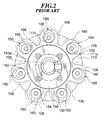
- FIG. 2 is a view of the swash plate 110 taken from a rear side of the compressor.
- the retainer 153 has its outer peripheral portion formed with a plurality of broken semi-annular portions 160 along its circumference through each of which a protruding portion 150a of each shoe 150 protrudes toward the piston 107.
- the retainer 153 is supported or held by a retainer support plate 155 which is fixed to a boss 110a of the swash plate 110 by bolts 154, such that the retainer 153 can perform relative rotation with respect to the retainer support plate 155.
- Torque of an engine, not shown, installed on an automotive vehicle, not shown, is transmitted to the drive shaft 105 to rotate the same.
- the torque of the drive shaft 105 is transmitted from the thrust flange 140 to the swash plate 110 via a linkage 141 to cause rotation of the swash plate 110.
- the rotation of the swash plate 110 causes relative rotation of each shoe 150 on the sliding surface 110a of the swash plate 110 with respect to the swash plate 110, whereby the torque transmitted from the swash plate 110 is converted into reciprocating motion of the piston 107.
- the volume of a compression chamber within the cylinder bore 106 changes, whereby suction, compression and delivery of refrigerant gas are carried out sequentially.
- the inclination of the swash plate 110 varies with pressure within a crankcase 108 in which the swash plate 110 is received, so that high-pressure refrigerant gas is delivered in an amount or volume corresponding to an inclination of the swash plate 110.
- the retainer 153 performs relative rotation (or sliding) with respect to the swash plate 110 while receiving tensile forces of pistons 107 in the suction stroke for drawing refrigerant gas into compression chambers, at corresponding portions of the retainer 153.
- the retainer support plate 155 supports or holds the retainer 153 in a state held in surface contact with a whole central portion of one face 153a of the retainer 153. Therefore, the conventional variable capacity swash plate compressor suffers from the inconvenience that when conditions of lubrication get worse, there occurs abrasion of sliding contact portions of the retainer 153 and the retainer support plate 155, and untoward noises are produced.
- the present invention provides a variable capacity swash plate compressor including a drive shaft, a rotating member rigidly fitted on the drive shaft, for rotation in unison with the drive shaft, a swash plate which is axially movably mounted on the drive shaft and tiltably connected to the rotating member, the swash plate having a sliding surface and a boss and rotating in unison with the rotating member as the rotating member rotates, a cylinder block, a plurality of cylinder bores axially formed through the cylinder block, a plurality of pistons slidably received in the cylinder bores, respectively, a plurality of shoes each arranged on the sliding surface of the swash plate for relative rotation with respect to the swash plate as the drive shaft rotates, a plurality of connecting rods each of which has one end slidably connected to a corresponding one of the shoes and another end connected to a corresponding one of the pistons, a retainer mounted on the swash plate in a relatively rotatable manner with respect
- variable capacity swash plate compressor is characterized in that the retainer support plate has an annular recess formed on a cylinder block-side open face thereof, for holding lubricating oil therein, and a lubricating oil supply hole formed through a compressing piston-side portion thereof which does not receive tensile forces from pistons in a suction stroke, for supplying the lubricating oil from the annular recess to the one face of the retainer therethrough.
- lubricating oil separates to be held within the annular recess and supplied via the lubricating oil supply hole to a clearance or interface between the retainer support plate and the retainer.
- the retainer and the compressing piston-side portion of the retainer support plate are not in intimate or tight contact with each other, which permits the lubricating oil held within the annular recess to be easily supplied all over sliding contact portions of the retainer and the retainer support plate via the lubricating oil supply hole formed through the compressing piston-side portion of the retainer support plate, thereby making smooth relative rotation (sliding) of the retainer with respect to the retainer support plate.
- the retainer has an oil-collecting portion formed around the lubricating oil supply hole, for collecting the lubricating oil held in the annular recess.
- lubricating oil held in the annular recess is collected in the oil-collecting portion and supplied in a sufficient amount via the lubricating oil supply hole to the clearance or interface between the retainer support plate and the retainer, so that the sliding contact portions of the retainer and the retainer support plate are positively lubricated, which makes it possible to reduce abrasion of the sliding contact portions of the two component parts of the compressor and at the same time prevent noises from being produced therefrom.
- the lubricating oil supply hole is formed close to a portion of the retainer which corresponds to a bottom dead center position of the each of the pistons.
- the lubricating oil supply hole is positioned at a location corresponding to an early stage of the compression stroke, so that lubricating oil supplied via this hole can easily flow between piston-compressing side portions of the retainer and the retainer support plate located backward with respect to the direction of rotation of the swash plate which are not in tight contact with each other, which permits the lubricating oil to be easily supplied all over sliding contact portions of the retainer and the retainer support plate, thereby making further smooth relative rotation (sliding) of the retainer with respect to the retainer support plate.
- the annular recess has a radial width which is largest at a location corresponding to the lubricating oil supply hole, and smallest at a location diametrically opposite to the location corresponding to the lubricating oil supply hole.
- FIG. 4 there is shown the whole arrangement of a variable capacity swash plate compressor according to a first embodiment of the invention.
- the variable capacity swash plate compressor has a cylinder block 1 having one end thereof secured to a rear head 3 via a valve plate 2 and the other end thereof secured to a front head 4.
- the cylinder block 1 has a plurality of cylinder bores 6 axially formed therethrough at predetermined circumferential intervals about a drive shaft 5 rotatably extending therethrough.
- Each cylinder bore 6 has a piston 7 slidably received therein.
- crankcase 8 Within the front head 4, there is formed a crankcase 8.
- the crankcase 8 has a swash plate 10 received therein, which rotates in unison with the drive shaft 5.
- a plurality of shoes 50 to each of which is slidably connected one end 11a, spherical in shape, of a corresponding one of connecting rods 11, are retained on a sliding surface 10a of the swash plate 10 by a retainer 53.
- the retainer 53 is mounted on a boss 10b of the swash plate 10 in a manner supported or held by a retainer support plate 55 in an annular form described hereinbelow.
- Each connecting rod 11 has the other end portion 11b thereof secured to a corresponding one of the pistons 7.
- Each piston 7 reciprocates within the cylinder bore 6 as the swash plate 10 rotates.
- the inclination of the swash plate 10 varies with pressure within the crankcase 8.
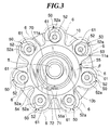
- FIG. 3 is a view of the swash plate 10 and component parts associated therewith, which is taken from the rear side of the compressor.
- FIGS. 5A and 5B show the retainer support plate 55 of the variable capacity swash plate compressor according to the first embodiment.
- FIG. 5A is a plan view of the retainer support plate, while FIG. 5B is a sectional view taken on line A-A of FIG. 5A.
- Each shoe 50 is comprised of a first support member 51 for slidably supporting a front-side surface of the one end 11a, spherical in shape, of a corresponding one of the connecting rods 11 such that the one spherical end 11a of the connecting rod 11 is relatively rotatable with respect to the first support member 51, and a second support member 52 for slidably supporting or retaining a rear-side surface of the one end 11a of the same such that rear-side surface of the one end 11a of the same is relatively rotatable with respect to the second support member 52.
- the retainer 53 is formed with a central through hole 53b which is fitted on a boss 10b of the swash plate 10. Further, the retainer 53 has its outer peripheral portion formed with a plurality of broken semi-annular portions 61 along the circumference thereof through each of which a protruding portion 52a of the second support member 52 of a corresponding one of the shoes 50 protrudes toward the piston 7.
- the retainer 53 is supported or held by the retainer support plate 55 which is fixed to the boss 10b of the swash plate 10 by a snap ring 54.
- the retainer support plate 55 is in surface contact with a central or inner portion of one face 53a of the retainer 53.
- the retainer support plate 55 has a cylinder block-side open face 55a formed with an annular recess 70 for holding lubricating oil.
- the annular recess 70 is formed therein with a lubricating oil supply hole 71 leading to the one face 53a of the retainer 53.
- the annular recess 70 has the same radial width along its whole circumference.
- the lubricating oil supply hole 71 is formed at a compressing piston-side portion (substantially left half as viewed in FIG. 5A) ⁇ of the retainer support plate 55.
- the lubricating oil supply hole 71 is located slightly away from a bottom dead center position of the retainer support plate 55 into the compression side.
- An oil-collecting portion 72 is formed around the lubricating oil supply hole 71 for collecting lubricating oil within the annular recess 70.
- the valve plate 2 is formed with refrigerant outlet ports 16 for respectively connecting the cylinder bores 6 with the discharge chamber 12 and refrigerant inlet ports 15 for respectively connecting the cylinder bores 6 with the suction chamber 13.
- the refrigerant outlet ports 16 and the refrigerant inlet ports 15 are arranged at predetermined circumferential intervals, respectively, about the drive shaft 5.
- Each refrigerant outlet port 16 is opened and closed by a discharge valve 17.
- the discharge valve 17 is fixed to a rear head-side end face of the valve plate 2 by a bolt 19 and nut 20 together with a valve stopper 18.
- each refrigerant inlet port 15 is opened and closed by a suction valve 21 arranged between a front-side end face of the valve plate 2 and the cylinder block 1.
- the bolt 19 has a guide hole 19a for guiding high-pressure refrigerant gas from the discharge chamber 12 to a radial bearing 24 and a thrust bearing 25.
- the radial bearing 24 and the thrust bearing 25 are arranged in the cylinder block 1 for rotatably supporting a rear-side end of the drive shaft 5, while a radial bearing 26 is arranged in the front head 4 for rotatably supporting a front-side end of the drive shaft 5.
- a communication passage 3a is formed for communication between the suction chamber 13 and the crankcase 8.
- a pressure control valve 32 is arranged at an intermediate portion of the communication passage 3a for controlling pressure within the suction chamber 13 and pressure within the crankcase 8.
- the drive shaft 5 has a thrust flange (rotating member) 40 rigidly fitted on a front-side portion thereof for transmitting torque of the drive shaft 5 to the swash plate 10.
- the thrust flange 40 is rotatably supported on an inner wall of the front head 4 by a thrust bearing 33.
- the thrust flange 40 and the swash plate 10 are connected with each other via a linkage 41.
- the swash plate 10 can tilt with respect to an imaginary plane perpendicular to the drive shaft 5.
- the linkage 41 is comprised of a bracket 10e formed on a front-side surface 10c of the swash plate 10, a guide slot 10f formed in the bracket 10e, and a rod 43 secured to a swash plate-side end surface 40a of the thrust flange 40 by screw.
- the longitudinal axis of the guide slot 10f is tilted through a predetermined angle with respect to the front-side surface 10c of the swash plate 10.
- a spherical end portion 43a of the rod 43 is relatively slidably engaged with the guide slot 10f.
- the swash plate 10 is mounted on the drive shaft 5 such that it is movable and tiltable in an axial direction.
- a coil spring 44 between the swash plate 10 and the thrust flange 40 to urge the swash plate 10 toward the cylinder block 1.
- a coil spring 47 is mounted on the drive shaft 5 between a stopper 45 fixedly fitted on the drive shaft 5 and the swash plate 10 to urge the swash plate 10 toward the thrust flange 40.
- variable capacity swash plate compressor constructed as above
- Torque of an engine, not shown, installed on an automotive vehicle, not shown, is transmitted to the drive shaft 5 to rotate the same.
- the torque of the drive shaft 5 is transmitted to the swash plate 10 via the thrust flange 40 and the linkage 41 to cause rotation of the swash plate.
- the rotation of the swash plate 10 causes relative rotation of each shoe 50 on the sliding surface 10a of the swash plate 10 with respect to the swash plate 10, whereby the torque transmitted from the swash plate 10 is converted into reciprocating motion of a piston 7 corresponding to the shoe 50.
- the piston 7 reciprocates within the cylinder bore 6, the volume of a compression chamber within the cylinder bore 6 changes.
- suction, compression and delivery of refrigerant gas are sequentially carried out in the compression chamber, whereby high-pressure refrigerant gas is delivered from the compression chamber in an amount corresponding to an inclination of the swash plate 10.
- the suction valve 21 opens to draw low-pressure refrigerant gas from the suction chamber 13 into the compression chamber within the cylinder bore 6.
- the discharge valve 17 opens to deliver the high-pressure refrigerant gas from the compression chamber to the discharge chamber 12.
- Lubricating oil within blow-by gas and the high-pressure refrigerant gas introduced via the guide hole 19a of the bolt 19 separates to be held in the annular recess 70 of the retainer support plate 55.
- the lubricating oil held in the annular recess 70 is collected in the oil-collecting portion 72 by centrifugal force to be supplied via the lubricating oil supply hole 71 to a clearance or interface between the retainer support plate 55 and the retainer 53.
- the lubricating oil supply hole 71 is formed through the compressing piston-side portion ⁇ of the retainer support plate 55 at a location slightly away from the bottom dead center position of the same as described above, so that the retainer 53 and the retainer support plate 55 are not in tight contact with each other, which permits the lubricating oil to be easily supplied all over the sliding contact portions of the retainer support plate 55 and the retainer 53. Therefore, the retainer 53 can perform smooth relative rotation (or sliding) with respect to the swash plate 10 while receiving tensile forces of pistons 7 in the suction stroke for drawing refrigerant gas into respective compression chambers.
- variable capacity swash plate compressor of the first embodiment lubricating oil is supplied via the lubricating oil supply hole 71 to the clearance or interface between the retainer support plate 55 and the retainer 53. Therefore, the sliding contact portions of the retainer 53 and the retainer support plate 55 are positively lubricated, which makes it possible to reduce abrasion of the sliding contact portions of the two component parts of the compressor and prevent noise from being produced.
- FIGS. 6A and 6B show a retainer support plate of a variable capacity swash plate compressor according to a second embodiment of the invention.
- FIG. 6A is a plan view of the retainer support plate
- FIG. 6B is a sectional view of the same taken on line B-B of FIG. 6A.
- Component parts and elements corresponding to those of the above embodiment are indicated by identical reference numerals, and description thereof is omitted.
- This embodiment is distinguished from the first embodiment, in which the annular recess 70 of the retainer support plate 55 has the same radial width along its whole circumference, in that, as shown in FIG. 6A, the retainer support plate 85 has an annular recess 90 whose radial width is largest in the vicinity of a lubricating oil supply hole 71, and smallest at a portion of the annular recess 90 diametrically opposite (with respect to the center of the retainer support plate 85) to the lubricating oil supply hole 71, i.e. 180 degrees circumferentially away from the lubricating oil supply hole 71.
- variable capacity swash plate compressor provides the same effects as obtained by the compressor of the first embodiment. Further, since lubricating oil is collected more efficiently in the vicinity of the lubricating oil supply hole 71, lubrication of the sliding contact portions of a retainer 53 and the retainer support plate 55 can be promoted, which makes it possible to positively prevent abrasion of the two sliding contact portions.
Landscapes
- Engineering & Computer Science (AREA)
- Mechanical Engineering (AREA)
- General Engineering & Computer Science (AREA)
- Manufacturing & Machinery (AREA)
- Compressors, Vaccum Pumps And Other Relevant Systems (AREA)
Applications Claiming Priority (3)
| Application Number | Priority Date | Filing Date | Title |
|---|---|---|---|
| JP9032638A JPH10213062A (ja) | 1997-01-31 | 1997-01-31 | 可変容量型斜板式圧縮機 |
| JP32638/97 | 1997-01-31 | ||
| JP3263897 | 1997-01-31 |
Publications (2)
| Publication Number | Publication Date |
|---|---|
| EP0856662A2 true EP0856662A2 (fr) | 1998-08-05 |
| EP0856662A3 EP0856662A3 (fr) | 1999-12-08 |
Family
ID=12364403
Family Applications (1)
| Application Number | Title | Priority Date | Filing Date |
|---|---|---|---|
| EP98300503A Withdrawn EP0856662A3 (fr) | 1997-01-31 | 1998-01-26 | Compresseur à plateau en biais à capacité variable |
Country Status (4)
| Country | Link |
|---|---|
| US (1) | US5941157A (fr) |
| EP (1) | EP0856662A3 (fr) |
| JP (1) | JPH10213062A (fr) |
| KR (1) | KR100274969B1 (fr) |
Families Citing this family (7)
| Publication number | Priority date | Publication date | Assignee | Title |
|---|---|---|---|---|
| DE19618757C2 (de) * | 1996-05-09 | 2001-02-22 | Witzig & Frank Turmatic Gmbh | Werkzeugmaschine |
| JP4280317B2 (ja) * | 1997-03-03 | 2009-06-17 | ルーク ファールツォイク−ヒドラウリク ゲーエムベーハー ウント コー. カーゲー | 特に自動車の空調設備のための圧縮機 |
| JP3880158B2 (ja) * | 1997-10-21 | 2007-02-14 | カルソニックカンセイ株式会社 | 斜板式圧縮機 |
| JP3479233B2 (ja) * | 1999-03-11 | 2003-12-15 | サンデン株式会社 | 可変容量斜板式圧縮機のカム機構 |
| KR100363406B1 (ko) * | 1999-08-05 | 2002-11-30 | 가부시키가이샤 도요다 지도숏키 | 용량가변형 사판식 압축기 |
| US20060285981A1 (en) * | 2005-06-21 | 2006-12-21 | Visteon Global Technologies, Inc. | Swash ring compressor with spherical bearing |
| DE102014209894A1 (de) * | 2014-05-23 | 2015-11-26 | Mahle International Gmbh | Axialkolbenmaschine |
Family Cites Families (10)
| Publication number | Priority date | Publication date | Assignee | Title |
|---|---|---|---|---|
| JPH0329586Y2 (fr) * | 1985-11-08 | 1991-06-24 | ||
| US4848101A (en) * | 1986-03-19 | 1989-07-18 | Diesel Kiki Co., Ltd. | Method and system for controlling capacity of variable capacity wobble plate compressor |
| DE58909319D1 (de) * | 1988-01-16 | 1995-08-03 | Michael Meyerle | Hydrostatische axialkolbenmaschine, insbesondere für ein kraftfahrzeuggetriebe mit leistungsverzweigung. |
| JPH0338461Y2 (fr) * | 1988-12-09 | 1991-08-14 | ||
| DK137493D0 (da) * | 1993-12-08 | 1993-12-08 | Danfoss As | Hydraulisk stempelmotor |
| DE4424608A1 (de) * | 1994-07-13 | 1996-01-18 | Danfoss As | Hydraulische Axialkolbenmaschine |
| JP3085514B2 (ja) * | 1995-06-08 | 2000-09-11 | 株式会社豊田自動織機製作所 | 圧縮機 |
| JPH09228945A (ja) * | 1996-02-22 | 1997-09-02 | Mitsubishi Electric Corp | 斜板式ポンプの潤滑機構 |
| JP3627358B2 (ja) * | 1996-03-26 | 2005-03-09 | 株式会社豊田自動織機 | 片側斜板式圧縮機 |
| JP3556430B2 (ja) * | 1997-04-22 | 2004-08-18 | サンデン株式会社 | 潤滑機構付き圧縮機 |
-
1997
- 1997-01-31 JP JP9032638A patent/JPH10213062A/ja not_active Withdrawn
-
1998
- 1998-01-13 US US09/006,665 patent/US5941157A/en not_active Expired - Fee Related
- 1998-01-26 EP EP98300503A patent/EP0856662A3/fr not_active Withdrawn
- 1998-01-31 KR KR1019980002692A patent/KR100274969B1/ko not_active Expired - Fee Related
Also Published As
| Publication number | Publication date |
|---|---|
| KR19980070978A (ko) | 1998-10-26 |
| KR100274969B1 (ko) | 2001-01-15 |
| JPH10213062A (ja) | 1998-08-11 |
| EP0856662A3 (fr) | 1999-12-08 |
| US5941157A (en) | 1999-08-24 |
Similar Documents
| Publication | Publication Date | Title |
|---|---|---|
| US5765464A (en) | Reciprocating pistons of piston-type compressor | |
| EP0698735B1 (fr) | Mécanisme de guidage pour piston alternatif de compresseur à piston | |
| EP0809024B1 (fr) | Piston alternatif de compresseur à piston | |
| US5931079A (en) | Variable capacity swash plate compressor | |
| US5941157A (en) | Variable capacity swash plate compressor | |
| EP0881386B2 (fr) | Compresseur à plateau en biais | |
| US5934170A (en) | Piston mechanism of fluid displacement apparatus | |
| US6019027A (en) | Refrigerant compressor | |
| EP0856663A2 (fr) | Compresseur à plateau en biais à capacité variable | |
| US6393964B1 (en) | Compressor having piston rotation restricting structure with lubricating inclined guide surface | |
| US5980216A (en) | Variable capacity swash plate compressor having a retainer support plate | |
| US5842406A (en) | Piston for compressors including a restrictor to prevent the piston from rotating | |
| JP2001027177A (ja) | 可変容量型斜板式圧縮機 | |
| US5937731A (en) | Variable capacity swash plate compressor | |
| US6044751A (en) | Variable displacement compressor | |
| US6050783A (en) | Reciprocating compressor in which a blowby gas can be returned into a suction chamber with a lubricating oil within a crank chamber kept at a sufficient level | |
| US6368073B1 (en) | Swash plate compressor | |
| EP0911521B1 (fr) | Gorges de lubrification dans le support rotatif d'un compresseur à plateau-came | |
| EP1211416B1 (fr) | Compresseur du type a plateau oscillant | |
| US20010003258A1 (en) | Reciprocating pistons of piston-type compressor | |
| EP1092873A2 (fr) | Alésages dans le cylindre d'un compresseur à plateau en biais | |
| JP4562661B2 (ja) | 斜板式圧縮機 |
Legal Events
| Date | Code | Title | Description |
|---|---|---|---|
| PUAI | Public reference made under article 153(3) epc to a published international application that has entered the european phase |
Free format text: ORIGINAL CODE: 0009012 |
|
| AK | Designated contracting states |
Kind code of ref document: A2 Designated state(s): DE FR GB |
|
| AX | Request for extension of the european patent |
Free format text: AL;LT;LV;MK;RO;SI |
|
| PUAL | Search report despatched |
Free format text: ORIGINAL CODE: 0009013 |
|
| AK | Designated contracting states |
Kind code of ref document: A3 Designated state(s): AT BE CH DE DK ES FI FR GB GR IE IT LI LU MC NL PT SE |
|
| AX | Request for extension of the european patent |
Free format text: AL;LT;LV;MK;RO;SI |
|
| AKX | Designation fees paid |
Free format text: DE FR GB |
|
| STAA | Information on the status of an ep patent application or granted ep patent |
Free format text: STATUS: THE APPLICATION IS DEEMED TO BE WITHDRAWN |
|
| 18D | Application deemed to be withdrawn |
Effective date: 20000609 |