EP0856690A2 - Drei- oder Vier-Wegeventil und Adapterstück - Google Patents
Drei- oder Vier-Wegeventil und Adapterstück Download PDFInfo
- Publication number
- EP0856690A2 EP0856690A2 EP97122133A EP97122133A EP0856690A2 EP 0856690 A2 EP0856690 A2 EP 0856690A2 EP 97122133 A EP97122133 A EP 97122133A EP 97122133 A EP97122133 A EP 97122133A EP 0856690 A2 EP0856690 A2 EP 0856690A2
- Authority
- EP
- European Patent Office
- Prior art keywords
- housing
- valve
- connection
- openings
- adapter piece
- Prior art date
- Legal status (The legal status is an assumption and is not a legal conclusion. Google has not performed a legal analysis and makes no representation as to the accuracy of the status listed.)
- Granted
Links
- 238000010438 heat treatment Methods 0.000 description 5
- 238000010276 construction Methods 0.000 description 3
- 238000009434 installation Methods 0.000 description 2
- 238000004519 manufacturing process Methods 0.000 description 2
- 230000007246 mechanism Effects 0.000 description 2
- 230000008901 benefit Effects 0.000 description 1
- 230000010354 integration Effects 0.000 description 1
- 230000004048 modification Effects 0.000 description 1
- 238000012986 modification Methods 0.000 description 1
- 238000005086 pumping Methods 0.000 description 1
- 230000008439 repair process Effects 0.000 description 1
Images


Classifications
-
- F—MECHANICAL ENGINEERING; LIGHTING; HEATING; WEAPONS; BLASTING
- F16—ENGINEERING ELEMENTS AND UNITS; GENERAL MEASURES FOR PRODUCING AND MAINTAINING EFFECTIVE FUNCTIONING OF MACHINES OR INSTALLATIONS; THERMAL INSULATION IN GENERAL
- F16K—VALVES; TAPS; COCKS; ACTUATING-FLOATS; DEVICES FOR VENTING OR AERATING
- F16K27/00—Construction of housing; Use of materials therefor
- F16K27/04—Construction of housing; Use of materials therefor of sliding valves
- F16K27/041—Construction of housing; Use of materials therefor of sliding valves cylindrical slide valves
Definitions
- the invention relates to a three- or four-way valve a valve actuator guided in the valve housing, the through an electronic, hydraulic or Pneumatic drive is actuated on the housing is attached.
- the invention also relates to a Adapter piece with a housing for connecting the three or Four-way valve on a centrifugal pump with front Inlet and outlet.
- the object of the invention is a valve of the beginning to improve the type mentioned so that at simple Design and manufacture an easy assembly and a high flexibility is made possible.
- the housing on the side opposite the drive forms a flat connection surface in which all inputs and Port openings of the valve and with the the housing on the flat surface of a Connection device can be fastened, the area of the Connection device with the inlet and outlet openings has matching openings.
- the exterior of the housing can have at least one gradation exhibit.
- Pad a flange or individual protrusions Attach to the connector.
- At least one channel in the Housing an annular or has annular section cross-section. Further is advantageous if at least one channel inside the housing is arranged coaxially to the housing axis.
- the housing and / or the insert are made of plastic.
- An advantage of the adapter piece according to the invention is that both the valves of the invention and commercially available valves on simple and inexpensive way with centrifugal pumps of the known type can be combined with front inlet and outlet can.
- the adapter piece only serves as Distributor of the medium flows to that between the pump and Multi-way valve arranged in the heating circuit.
- a modular structure is supported by the adapter piece.
- the modular structure offers a particularly inexpensive Solution.
- the modular structure also allows the Assembly of the components, in the simplest case be screwed together automatically.
- the installation of the Multi-way valve in the flow or return of the Boiler possible.
- the adapter piece has one Outlet and two inlets or one inlet and two Discharge in the third connection area.
- the adapter piece with the integrated guide channels in one piece made of plastic shapes in particular to inject.
- the Connection areas (flanges) of the adapter piece according to the connection standard of the pump, the valve and of the heating circuit components. Because with that Adapter piece the distance between the front and the Back surface is smaller than the height and width of the It is possible to use one valve while consuming a housing small space to connect to a pump.
- the Front surface a third connection area with the Openings for the main lines so that the Adapter piece simply between the pump and one Boiler can be installed.
- the connection openings for the main lines in the side walls of the housing introduced and complete with standard flanges, so that easy integration of the valve in any Heating circuit is possible.
- the three- or four-way valve has a housing 1, that is rotationally symmetrical to the housing axis 2 and and whose in particular coaxial outer wall 3 is stepped can be shaped.
- a drive 4 fastens the, electrically, hydraulically or pneumatically via a coaxial rod 5 Valve actuator 6 actuated.
- valve actuator 6 works with valve seats 7a, 7b together by the outer wall 3 and / or by a coaxial insert 8 are formed by the the drive 4 opposite end of the housing 1 is insertable and in particular held clamped becomes.
- the end of the drive 4 opposite Housing 1 forms a flat connecting surface 9 Inlets 10a and 10b and at least one Outlet 11.
- the inlet ports 10a and 10b are through the partially annular space between the Inner wall and the outer wall 3 of the insert 8 are formed.
- the outlet opening 11 is from the outer end of the interior of insert 8 formed.
- the insert 8 thus forms an inner channel 13 which leads to the outlet opening 11 and outer channels 14 which in lead the inlet openings 10a and 10b.
- the housing 1 and the insert 8 are preferably made of plastic.
- Figures 3 and 4 differs differs from that according to FIGS. 1 and 2 essentially by that the insert, the valve actuator and the valve seats are shaped differently in order to thereby in particular a to get another function of the valve.
- FIGS. 3 and 4 differs from that according to FIGS. 3 and 4 in that the Valve actuator 6 by a hydraulic drive is adjustable while the drives of the other two Embodiments preferably electrical in particular are magnetic.
- a control line 15 is guided through the housing 1, the hydraulic pressure from the pad 9 to Drive leads. This will also control the control line Pad 9 on the connector or from the Surface of the boiler or from an intermediate device provided.
- FIG. 7 shows an adapter piece with a housing 16 shown between an electric motor 17 operated centrifugal pump 18 and an inventive Three-way valve 26 with housing 1 is arranged.
- the Housing 16 of the adapter piece has two parallel ones Base areas on a flat front surface 24 and one form flat rear surface 19.
- the base areas 19 and 24 are connected via vertically arranged side walls 27.
- the figure was largely based on the representation of the master channels. Instead they are Flow of the medium with broken arrows shown schematically.
- the adapter piece has a rear surface 19 first connection area 20, which in the illustrated Embodiment two openings 21 and 22 for the Connection of the centrifugal pump 18 has. Via opening 21 the suction port of the centrifugal pump 18 is supplied, while via the opening 22 of the pressure port of the pump 18th is connected to a straight passage 23 which between the rear surface 19 and the front surface 24 of the housing 16 runs. Via the passage 23, the pump medium from Pressure port of the centrifugal pump 18 to one Pumped boiler shown (arrow A) -
- the adapter piece also has on its rear surface 19 a second connection area 25 with openings for the Connection of the three-way valve 26 on.
- the second Connection area 25 located, not shown Openings correspond to the openings in their arrangement as shown in Figures 2, 4 and 6.
- the adapter piece has one on its front surface 24 third connection area 28 with three openings leading to the not shown boiler. In a first 29 The passage 23 opens out of the three openings.
- the other two openings are inlet openings 30.
- Im Housing 16 are molded in one piece from plastic Guide channels arranged so that the pumping medium from the Inlet openings 30 to the inlet openings of the valve 26 guide (arrows B and C). This occurs from the valve 26 Pump medium in the interior of the housing 16 and from there to the suction port of the pump 18 (arrow D).
- Adapter piece is a vent 31 on the housing 16 attached, via which the air from the Heating system can escape.
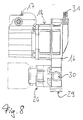
- FIG 8 is an embodiment of the adapter piece shown in which the openings 29 and 30 at which the Main lines are connected in the side walls 27 of the housing 16 are introduced.
- This Embodiment also has a vent 31 of FIG known type on.
Landscapes
- Engineering & Computer Science (AREA)
- General Engineering & Computer Science (AREA)
- Mechanical Engineering (AREA)
- Valve Housings (AREA)
- Fluid-Pressure Circuits (AREA)
Abstract
Description
- Figur 1
- einen Längsschnitt durch ein erstes Ausführungsbeispiel des Ventils
- Figur 2
- die Anschlußfläche des ersten Ausführungsbeispiels
- Figur 3
- einen Längsschnitt durch ein zweites Ausführungsbeispiel
- Figur 4
- die Anschlußfläche des zweiten Ausführungsbeispiels
- Figur 5
- ein drittes Ausführungsbeispiel und
- Figur 6
- die Anschlußfläche des dritten Ausführungsbeispiels
- Figur 7
- ein Adapterstück zwischen einer Pumpe und einem Ventil und
- Figur 8
- ein Adapterstück mit Anschlußöffnungen in den Seitenwänden
Claims (20)
- Drei- oder Vier-Wegeventil mit einem im Ventilgehäuse (1) geführten Ventilstellglied (6), das durch einen elektronischen, hydraulischen oder pneumatischen Antrieb (4) betätigbar ist, der am Gehäuse (1) befestigt ist, dadurch gekennzeichnet, daß das Gehäuse (1) auf der dem Antrieb (4) gegenüberliegenden Seite eine ebene Anschlußfläche (9) bildet, in der sich alle Ein- und Auslaßöffnungen des Ventils befinden und mit der das Gehäuse (1) an der ebenen Fläche einer Anschlußvorrichtung befestigbar ist, wobei die Fläche der Anschlußvorichtung mit den Ein- und Auslaßöffnungen übereinstimmende Öffnungen aufweist.
- Ventil nach Anspruch 1, dadurch gekennzeichnet, daß die Wege insbesondere Kanäle (13, 14) im Gehäuseinneren, von einem separaten Einsatz (8) gebildet sind, der innerhalb der Außenwände des Gehäuses (1) liegt.
- Ventil nach Anspruch 1 oder 2, dadurch gekennzeichnet, daß von der ebenen Anschlußfläche (9) zum Antrieb (4) eine hydraulische oder pneumatische Steuerleitung (15) durch das Gehäuse (1) läuft.
- Ventil nach einem der vorherigen Ansprüche, dadurch gekennzeichnet, daß das Gehäuseäußere rotationssymmetrisch zu einer Achse (2) ist, die eine Normale zur Anschlußfläche (9) bildet.
- Ventil nach Anspruch 4, dadurch gekennzeichnet, daß das Gehäuseäußere mindestens eine Abstufung aufweist.
- Ventil nach einem der vorherigen Ansprüche, dadurch gekennzeichnet, daß am äußeren Rand der Anschlußfläche (9) ein Flansch oder einzelne Vorsprünge zum Befestigen an der Anschlußvorrichtung sind.
- Ventil nach einem der vorherigen Ansprüche, dadurch gekennzeichnet, daß das Gehäuse (1) aus Kunststoff besteht.
- Ventil nach einem der vorherigen Ansprüche, dadurch gekennzeichnet, daß mindestens ein Kanal (14) im Gehäuseinneren einen ringförmigen oder ringabschnittförmigen Querschnitt aufweist.
- Ventil nach einem der vorherigen Ansprüche, dadurch gekennzeichnet, daß mindestens ein Kanal (13, 14) im Gehäuseinneren koaxial zur Gehäuseachse (2) angeordnet ist.
- Ventil nach einem der Ansprüche 2 bis 9, dadurch gekennzeichnet, daß der Einsatz (8) aus Kunststoff besteht.
- Adapterstück mit einem Gehäuse zum Anschluß für ein Drei- oder Vier-Wegeventil insbesondere nach einem der der Ansprüche 1 bis 10 an eine Kreiselpumpe,
dadurch gekennzeichnet,daß das Gehäuse (16) Grundflächen aufweist, die eine ebene Vorderfläche (24) und eine dazu parallele ebene Rückfläche (19) bilden,daß das Gehäuse (16) Öffnungen (29-30) für den Anschluß von Hauptleitungen aufweist,daß die Rückfläche (19) einen ersten Anschlußbereich (20) mit Öffnungen (21,22) für den Anschluß der Kreiselpumpe (18) aufweist,daß die Vorder- (24) oder Rückfläche (19) einen zweiten Anschlußbereich (25) mit Öffnungen für den Anschluß des Drei- oder Vier-Wegeventiles (26) aufweist unddaß im Gehäuse (16) entsprechende Leitkanäle vom ersten (20) zum zweiten Anschlußbereich (25) und von dort zu den Öffnungen (29,30) zum Anschluß der Hauptleitungen angeordnet sind. - Adapterstück nach Anspruch 11,dadurch gekennzeichnet, daß die Vorderfläche (24) einen dritten Anschlußbereich (28) mit den Öffnungen (29,30) zum Anschluß der Hauptleitungen aufweist.
- Adapterstück nach Anspruch 11 oder 12, dadurch gekennzeichnet, daß der Abstand zwischen der Vorderfläche (24) und der Rückfläche (19) kleiner ist als die Höhe und kleiner ist als die Breite des Gehäuses (16).
- Adapterstück nach einem der vorherigen Ansprüche dadurch gekennzeichnet, daß Gehäuse (16) und Leitkanäle einstückig aus Kunststoff geformt sind.
- Adapterstück nach einem der vorherigen Ansprüche, dadurch gekennzeichnet, daß am Gehäuse (16) ein Entlüfter (31) angebracht ist.
- Adapterstück nach einem der vorherigen Ansprüche, dadurch gekennzeichnet, daß der dritte Anschlußbereich (25) in der Rückfläche (19) angeordnet ist.
- Adapterstück nach einem der vorherigen Ansprüche, dadurch gekennzeichnet, daß das Gehäuse (16) einen geraden Durchlaß (23) zwischen den beiden Grundflächen (19,24) aufweist, der eine Hauptleitung mit der Druckseite der Kreiselpumpe (18) verbindet.
- Adapterstück nach einem der vorherigen Ansprüche, dadurch gekennzeichnet, daß die Vorderfläche (24) direkt auf eine Anschlußfläche eines Heizkessels aufsetzbar ist.
- Adapterstück nach einem der vorherigen Ansprüche, dadurch gekennzeichnet, daß im Gehäuse (16) mindestens ein Ventil angeordnet ist, mit dem Leitkanäle verbindbar sind oder mit dem ein Leitkanal verschließbar ist.
- Adapterstück nach einem der vorherigen Ansprüche, dadurch gekennzeichnet, daß die Öffnungen (29,30) für den Anschluß der Hauptleitungen in die Seitenwände (27) des Gehäuses (16) eingebracht sind.
Applications Claiming Priority (4)
| Application Number | Priority Date | Filing Date | Title |
|---|---|---|---|
| DE19653084 | 1996-12-19 | ||
| DE19653084 | 1996-12-19 | ||
| DE19711085 | 1997-03-18 | ||
| DE19711085A DE19711085A1 (de) | 1996-12-19 | 1997-03-18 | Drei- oder Vier-Wegeventil und Adapterstück |
Publications (3)
| Publication Number | Publication Date |
|---|---|
| EP0856690A2 true EP0856690A2 (de) | 1998-08-05 |
| EP0856690A3 EP0856690A3 (de) | 1998-12-16 |
| EP0856690B1 EP0856690B1 (de) | 2003-03-05 |
Family
ID=26032475
Family Applications (1)
| Application Number | Title | Priority Date | Filing Date |
|---|---|---|---|
| EP19970122133 Expired - Lifetime EP0856690B1 (de) | 1996-12-19 | 1997-12-16 | Drei- oder Vier-Wegeventil |
Country Status (1)
| Country | Link |
|---|---|
| EP (1) | EP0856690B1 (de) |
Cited By (1)
| Publication number | Priority date | Publication date | Assignee | Title |
|---|---|---|---|---|
| EP2028749A1 (de) * | 2007-08-21 | 2009-02-25 | ARI-Armaturen Albert Richter GmbH & Co. KG | Ansteuerbare Antriebsvorrichtung |
Family Cites Families (7)
| Publication number | Priority date | Publication date | Assignee | Title |
|---|---|---|---|---|
| DE1500064A1 (de) * | 1965-01-30 | 1969-05-08 | Herion Erich | Durchgangs- oder Mehrwegeventil |
| US3817269A (en) * | 1969-08-22 | 1974-06-18 | Int Basic Economy Corp | Integrated manifold circuits |
| US3976103A (en) * | 1973-10-19 | 1976-08-24 | Rockford Servo Corporation | Sliding spool type valve and method of making the same |
| DE2547847A1 (de) * | 1975-10-25 | 1977-05-05 | Beukenberg Maschf | Vorrichtung zur verteilung von hydraulischen oder pneumatischen arbeitsmedien |
| DE3334160C2 (de) * | 1983-09-21 | 1986-07-24 | Sauer, Otto, 6800 Mannheim | Magnetventil |
| DE9106236U1 (de) * | 1991-05-21 | 1992-09-17 | IMAV-Hydraulik GmbH, 4005 Meerbusch | Verkettetes Hydrauliksystem |
| DE19629217A1 (de) * | 1996-07-19 | 1998-01-22 | Eckehart Schulze | Hydraulikventil |
-
1997
- 1997-12-16 EP EP19970122133 patent/EP0856690B1/de not_active Expired - Lifetime
Non-Patent Citations (1)
| Title |
|---|
| None |
Cited By (1)
| Publication number | Priority date | Publication date | Assignee | Title |
|---|---|---|---|---|
| EP2028749A1 (de) * | 2007-08-21 | 2009-02-25 | ARI-Armaturen Albert Richter GmbH & Co. KG | Ansteuerbare Antriebsvorrichtung |
Also Published As
| Publication number | Publication date |
|---|---|
| EP0856690B1 (de) | 2003-03-05 |
| EP0856690A3 (de) | 1998-12-16 |
Similar Documents
| Publication | Publication Date | Title |
|---|---|---|
| DE69124736T2 (de) | Ventilverteiler | |
| DE2030044A1 (de) | Verteilerblock fur Fluid Steuerventile | |
| DE19726281A1 (de) | Fluidpumpe | |
| DE19537482A1 (de) | Hydraulischer Steuerblock | |
| DE2851155A1 (de) | Hydraulisches versorgungsaggregat | |
| EP1130342B1 (de) | Baueinheit für eine Kompaktheizungsanlage | |
| DE29808570U1 (de) | Ventil-Verteileranordnung | |
| EP0774583B1 (de) | Gehäuse für eine Kreiselpumpe | |
| EP2107284B1 (de) | Ventilgehäuserohling, Ventilbausatz sowie Ventilgruppe | |
| EP0137154B1 (de) | Mehrwege-Hahn | |
| DE19711085A1 (de) | Drei- oder Vier-Wegeventil und Adapterstück | |
| DE2722269A1 (de) | Vorrichtung zur schnellen entleerung einer kammer eines pneumatischen zylinders | |
| EP0856690A2 (de) | Drei- oder Vier-Wegeventil und Adapterstück | |
| DE4219679C1 (de) | Ventilanordnung | |
| DE2335915A1 (de) | Einrichtung zur halterung und verbindung in serie geschalteter steuer- und/ oder konditioniervorrichtungen fuer ein fluid | |
| DE10039072C2 (de) | Ventilanordnung | |
| DE3313352C2 (de) | ||
| EP0791772A2 (de) | Dreiwegeventil für hydraulische Schnittstelle | |
| EP0866280B1 (de) | Anschlussadapter | |
| DE3009599A1 (de) | Unterputz-anschlusskasten fuer sanitaerarmaturen | |
| EP0952410A2 (de) | Heizkörper | |
| DE19545021B4 (de) | Elektromagnetisch betätigtes Wegeventil | |
| DE19632604A1 (de) | Befülleinrichtung für Hydraulikbaugruppe | |
| DE4229054A1 (de) | Funktionsbaustein, insbesondere für pneumatische Medien | |
| DE9112021U1 (de) | Wasserauslaufarmatur |
Legal Events
| Date | Code | Title | Description |
|---|---|---|---|
| PUAI | Public reference made under article 153(3) epc to a published international application that has entered the european phase |
Free format text: ORIGINAL CODE: 0009012 |
|
| AK | Designated contracting states |
Kind code of ref document: A2 Designated state(s): DE FR IT NL |
|
| AX | Request for extension of the european patent |
Free format text: AL;LT;LV;MK;RO;SI |
|
| PUAL | Search report despatched |
Free format text: ORIGINAL CODE: 0009013 |
|
| AK | Designated contracting states |
Kind code of ref document: A3 Designated state(s): AT BE CH DE DK ES FI FR GB GR IE IT LI LU MC NL PT SE |
|
| AX | Request for extension of the european patent |
Free format text: AL;LT;LV;MK;RO;SI |
|
| 17P | Request for examination filed |
Effective date: 19981128 |
|
| AKX | Designation fees paid |
Free format text: DE FR IT NL |
|
| 17Q | First examination report despatched |
Effective date: 20010417 |
|
| RTI1 | Title (correction) |
Free format text: THREE OR FOUR WAY VALVE |
|
| GRAG | Despatch of communication of intention to grant |
Free format text: ORIGINAL CODE: EPIDOS AGRA |
|
| GRAG | Despatch of communication of intention to grant |
Free format text: ORIGINAL CODE: EPIDOS AGRA |
|
| GRAH | Despatch of communication of intention to grant a patent |
Free format text: ORIGINAL CODE: EPIDOS IGRA |
|
| GRAH | Despatch of communication of intention to grant a patent |
Free format text: ORIGINAL CODE: EPIDOS IGRA |
|
| RAP1 | Party data changed (applicant data changed or rights of an application transferred) |
Owner name: WILO AG |
|
| GRAA | (expected) grant |
Free format text: ORIGINAL CODE: 0009210 |
|
| AK | Designated contracting states |
Designated state(s): DE FR IT NL |
|
| REF | Corresponds to: |
Ref document number: 59709436 Country of ref document: DE Date of ref document: 20030410 Kind code of ref document: P |
|
| ET | Fr: translation filed | ||
| PLBE | No opposition filed within time limit |
Free format text: ORIGINAL CODE: 0009261 |
|
| STAA | Information on the status of an ep patent application or granted ep patent |
Free format text: STATUS: NO OPPOSITION FILED WITHIN TIME LIMIT |
|
| 26N | No opposition filed |
Effective date: 20031208 |
|
| PGFP | Annual fee paid to national office [announced via postgrant information from national office to epo] |
Ref country code: IT Payment date: 20131213 Year of fee payment: 17 Ref country code: NL Payment date: 20131210 Year of fee payment: 17 |
|
| PGFP | Annual fee paid to national office [announced via postgrant information from national office to epo] |
Ref country code: DE Payment date: 20141209 Year of fee payment: 18 |
|
| PGFP | Annual fee paid to national office [announced via postgrant information from national office to epo] |
Ref country code: FR Payment date: 20141208 Year of fee payment: 18 |
|
| REG | Reference to a national code |
Ref country code: NL Ref legal event code: V1 Effective date: 20150701 |
|
| REG | Reference to a national code |
Ref country code: NL Ref legal event code: V1 Effective date: 20150701 |
|
| PG25 | Lapsed in a contracting state [announced via postgrant information from national office to epo] |
Ref country code: NL Free format text: LAPSE BECAUSE OF NON-PAYMENT OF DUE FEES Effective date: 20150701 |
|
| PG25 | Lapsed in a contracting state [announced via postgrant information from national office to epo] |
Ref country code: IT Free format text: LAPSE BECAUSE OF NON-PAYMENT OF DUE FEES Effective date: 20141216 |
|
| REG | Reference to a national code |
Ref country code: DE Ref legal event code: R119 Ref document number: 59709436 Country of ref document: DE |
|
| REG | Reference to a national code |
Ref country code: FR Ref legal event code: ST Effective date: 20160831 |
|
| PG25 | Lapsed in a contracting state [announced via postgrant information from national office to epo] |
Ref country code: DE Free format text: LAPSE BECAUSE OF NON-PAYMENT OF DUE FEES Effective date: 20160701 |
|
| PG25 | Lapsed in a contracting state [announced via postgrant information from national office to epo] |
Ref country code: FR Free format text: LAPSE BECAUSE OF NON-PAYMENT OF DUE FEES Effective date: 20151231 |