EP0856723A2 - Verbesserungen an oder in Bezug auf Massendurchflussmessung - Google Patents
Verbesserungen an oder in Bezug auf Massendurchflussmessung Download PDFInfo
- Publication number
- EP0856723A2 EP0856723A2 EP97308677A EP97308677A EP0856723A2 EP 0856723 A2 EP0856723 A2 EP 0856723A2 EP 97308677 A EP97308677 A EP 97308677A EP 97308677 A EP97308677 A EP 97308677A EP 0856723 A2 EP0856723 A2 EP 0856723A2
- Authority
- EP
- European Patent Office
- Prior art keywords
- bulk material
- mass flow
- measuring apparatus
- flow measuring
- sensor
- Prior art date
- Legal status (The legal status is an assumption and is not a legal conclusion. Google has not performed a legal analysis and makes no representation as to the accuracy of the status listed.)
- Granted
Links
- 238000005259 measurement Methods 0.000 title claims description 40
- 230000006872 improvement Effects 0.000 title description 3
- 239000013590 bulk material Substances 0.000 claims abstract description 95
- 230000002093 peripheral effect Effects 0.000 claims abstract description 16
- 238000000034 method Methods 0.000 claims abstract description 9
- 230000000694 effects Effects 0.000 claims description 22
- 239000000463 material Substances 0.000 claims description 11
- 230000005484 gravity Effects 0.000 claims description 5
- 239000008187 granular material Substances 0.000 abstract description 3
- 241001124569 Lycaenidae Species 0.000 description 5
- 238000004140 cleaning Methods 0.000 description 4
- 238000006073 displacement reaction Methods 0.000 description 4
- 238000012937 correction Methods 0.000 description 3
- 230000007246 mechanism Effects 0.000 description 3
- 230000003287 optical effect Effects 0.000 description 3
- 230000008859 change Effects 0.000 description 2
- 238000010276 construction Methods 0.000 description 2
- 238000003306 harvesting Methods 0.000 description 2
- 239000000126 substance Substances 0.000 description 2
- 241000251169 Alopias vulpinus Species 0.000 description 1
- 230000008901 benefit Effects 0.000 description 1
- 238000011088 calibration curve Methods 0.000 description 1
- 239000003245 coal Substances 0.000 description 1
- 230000000295 complement effect Effects 0.000 description 1
- 239000000356 contaminant Substances 0.000 description 1
- 230000001419 dependent effect Effects 0.000 description 1
- 239000000428 dust Substances 0.000 description 1
- 235000013399 edible fruits Nutrition 0.000 description 1
- 238000005516 engineering process Methods 0.000 description 1
- 239000004459 forage Substances 0.000 description 1
- 230000006870 function Effects 0.000 description 1
- 238000010348 incorporation Methods 0.000 description 1
- 229910052500 inorganic mineral Inorganic materials 0.000 description 1
- 230000010354 integration Effects 0.000 description 1
- 239000007788 liquid Substances 0.000 description 1
- 239000011707 mineral Substances 0.000 description 1
- 230000001095 motoneuron effect Effects 0.000 description 1
- 239000002245 particle Substances 0.000 description 1
- 239000000843 powder Substances 0.000 description 1
- 238000009877 rendering Methods 0.000 description 1
- 239000000725 suspension Substances 0.000 description 1
- 238000012360 testing method Methods 0.000 description 1
- 210000001364 upper extremity Anatomy 0.000 description 1
- 235000013311 vegetables Nutrition 0.000 description 1
- 238000005303 weighing Methods 0.000 description 1
Images


Classifications
-
- G—PHYSICS
- G01—MEASURING; TESTING
- G01F—MEASURING VOLUME, VOLUME FLOW, MASS FLOW OR LIQUID LEVEL; METERING BY VOLUME
- G01F1/00—Measuring the volume flow or mass flow of fluid or fluent solid material wherein the fluid passes through a meter in a continuous flow
- G01F1/66—Measuring the volume flow or mass flow of fluid or fluent solid material wherein the fluid passes through a meter in a continuous flow by measuring frequency, phase shift or propagation time of electromagnetic or other waves, e.g. using ultrasonic flowmeters
- G01F1/663—Measuring the volume flow or mass flow of fluid or fluent solid material wherein the fluid passes through a meter in a continuous flow by measuring frequency, phase shift or propagation time of electromagnetic or other waves, e.g. using ultrasonic flowmeters by measuring Doppler frequency shift
-
- A—HUMAN NECESSITIES
- A01—AGRICULTURE; FORESTRY; ANIMAL HUSBANDRY; HUNTING; TRAPPING; FISHING
- A01D—HARVESTING; MOWING
- A01D41/00—Combines, i.e. harvesters or mowers combined with threshing devices
- A01D41/12—Details of combines
- A01D41/127—Control or measuring arrangements specially adapted for combines
- A01D41/1271—Control or measuring arrangements specially adapted for combines for measuring crop flow
- A01D41/1272—Control or measuring arrangements specially adapted for combines for measuring crop flow for measuring grain flow
-
- G—PHYSICS
- G01—MEASURING; TESTING
- G01F—MEASURING VOLUME, VOLUME FLOW, MASS FLOW OR LIQUID LEVEL; METERING BY VOLUME
- G01F1/00—Measuring the volume flow or mass flow of fluid or fluent solid material wherein the fluid passes through a meter in a continuous flow
- G01F1/05—Measuring the volume flow or mass flow of fluid or fluent solid material wherein the fluid passes through a meter in a continuous flow by using mechanical effects
- G01F1/20—Measuring the volume flow or mass flow of fluid or fluent solid material wherein the fluid passes through a meter in a continuous flow by using mechanical effects by detection of dynamic effects of the flow
- G01F1/206—Measuring pressure, force or momentum of a fluid flow which is forced to change its direction
-
- G—PHYSICS
- G01—MEASURING; TESTING
- G01F—MEASURING VOLUME, VOLUME FLOW, MASS FLOW OR LIQUID LEVEL; METERING BY VOLUME
- G01F1/00—Measuring the volume flow or mass flow of fluid or fluent solid material wherein the fluid passes through a meter in a continuous flow
- G01F1/05—Measuring the volume flow or mass flow of fluid or fluent solid material wherein the fluid passes through a meter in a continuous flow by using mechanical effects
- G01F1/20—Measuring the volume flow or mass flow of fluid or fluent solid material wherein the fluid passes through a meter in a continuous flow by using mechanical effects by detection of dynamic effects of the flow
- G01F1/28—Measuring the volume flow or mass flow of fluid or fluent solid material wherein the fluid passes through a meter in a continuous flow by using mechanical effects by detection of dynamic effects of the flow by drag-force, e.g. vane type or impact flowmeter
- G01F1/30—Measuring the volume flow or mass flow of fluid or fluent solid material wherein the fluid passes through a meter in a continuous flow by using mechanical effects by detection of dynamic effects of the flow by drag-force, e.g. vane type or impact flowmeter for fluent solid material
-
- G—PHYSICS
- G01—MEASURING; TESTING
- G01F—MEASURING VOLUME, VOLUME FLOW, MASS FLOW OR LIQUID LEVEL; METERING BY VOLUME
- G01F1/00—Measuring the volume flow or mass flow of fluid or fluent solid material wherein the fluid passes through a meter in a continuous flow
- G01F1/76—Devices for measuring mass flow of a fluid or a fluent solid material
- G01F1/78—Direct mass flowmeters
- G01F1/80—Direct mass flowmeters operating by measuring pressure, force, momentum, or frequency of a fluid flow to which a rotational movement has been imparted
-
- G—PHYSICS
- G01—MEASURING; TESTING
- G01F—MEASURING VOLUME, VOLUME FLOW, MASS FLOW OR LIQUID LEVEL; METERING BY VOLUME
- G01F25/00—Testing or calibration of apparatus for measuring volume, volume flow or liquid level or for metering by volume
- G01F25/10—Testing or calibration of apparatus for measuring volume, volume flow or liquid level or for metering by volume of flowmeters
-
- A—HUMAN NECESSITIES
- A01—AGRICULTURE; FORESTRY; ANIMAL HUSBANDRY; HUNTING; TRAPPING; FISHING
- A01D—HARVESTING; MOWING
- A01D41/00—Combines, i.e. harvesters or mowers combined with threshing devices
- A01D41/12—Details of combines
- A01D41/127—Control or measuring arrangements specially adapted for combines
- A01D41/1271—Control or measuring arrangements specially adapted for combines for measuring crop flow
Definitions
- This invention relates to improvements in or relating to mass flow measurement, which is the measurement of the mass flow rate of so-called "bulk” materials.
- Such materials include but are not limited to grain, forage, granular chemicals, powders, fruit, vegetables, coal, minerals, ores and high viscosity liquids.
- the invention has particular application to the measurement of the mass flow rate of grain to the grain tank of a combine harvester.
- a mass flow measuring apparatus including a sensor member having a surface along which the streamline flow of bulk material may occur thereby giving rise to forces, moments or torques in the sensor member that are measurable.
- Strain gauges, optical displacement sensors, ring dynamometers and torque meters can be used to produce electrical signals indicative of the magnitudes of the forces, moments or torques, thereby providing an indication of the mass flow rate of bulk material.
- Co-pending European Patent Application No. 96201889.1 discloses a method and apparatus for rendering the measurements of mass flow rate measuring apparatuses more accurate, by substantially eliminating the effects of changes in the coefficient of friction ( ⁇ ) between the bulk material and the sensor surface on the measured mass flow rate values. Nonetheless, there is scope for improvement of the accuracy of such measuring apparatuses, as detailed below.
- Mass flow measuring apparatuses may be employed, e.g. in grain and chemical hoppers, railway tankers and waggons, silos and crop harvesting machines such as combine harvesters.
- the grain elevator is a paddle-type device having a series of shaped paddles or buckets mounted on an endless drive chain or other flexible member that is powered at a constant speed from the engine of the vehicle.
- the flexible chain extends substantially vertically over the majority of its length, and is positioned such that the paddles or buckets repeatedly pick up quantities of grain at a low level in the cleaning area below the threshing area of the combine harvester and raise them to the bubble up auger.
- the motion of the grain elevator is such as to throw the quantities of grain clear of the paddles, towards the bubble up auger, when they reach the correct height.
- Previous proposals for mass flow measuring apparatuses involve locating a sensor surface so that it forms part of the path of the grains between the paddles at the top of the elevator and the base of the bubble up auger. Thus it is possible to establish streamline flow of grains on the sensor surface by guiding the projected grains (via a further surface at a tangent to the end of the sensor surface) to the end of the sensor surface.
- the sensor surface lies above the grains for the greater part of their travel therealong, the forces, moments or torques in the sensor member being generated principally by centrifugal forces transmitted from the grains to the surface; and by the effects of friction between the gains and the material of the sensor surface.
- each paddle or bucket on the grain elevator contains grain to a depth of several centimetres, it will be appreciated that not every grain from a paddle or bucket on the elevator is projected at the same velocity and with the same momentum. Thus some of the grains fail to reach the sensor member and tend to fall downwardly beside the grain elevator. Such grains may fall to the bottom of the conveyor housing and add to the volume of freshly threshed grain. Eventually, recurrently recycled grains become milled between the moving components and the walls of the conveyor.
- the grains that fall away from the sensor member can lead to inaccuracies in the measured flow rate.
- an impeller apparatus for bulk material comprising a material engaging portion having a surface including a root zone and a peripheral zone, the surface being movable along a locus whereby to impart a peripherally directed force to bulk material engaged by the surface; and a drive for driving the surface at a predetermined speed along the locus; the surface being so inclined relative to at least one point on the locus that bulk material engaged by the surface moves towards the peripheral zone when the surface passes the or each such point at least at the predetermined speed, thereby permitting projection of bulk material from the impeller.
- the impeller is located to engage, energise and re-project those grains as referred to above that are of low momentum and therefore either fail to contact the sensor surface or contact the sensor surface for only a part of its length.
- the apparatus of the invention thus advantageously reduces the wastage of grains in a combine harvester and also renders the measurements of a mass flow measuring apparatus more accurate.
- the invention is also considered to reside in a mass flow measuring apparatus including an impeller as defined herein.
- the impeller assists a conveyor in conveying bulk material to a sensor member.
- the mass flow measuring apparatus includes means for matching the speed of ejection of bulk material from the impeller to the speed of conveyance of bulk material by the conveyor.
- this is readily achieved by means of a gearing system that matches the speed of the periphery of the impeller surface to the speed of grains or other bulk material conveyed by the outer portions of the conveyor paddles or buckets.
- the speed of bulk material in the conveyor is essentially the same as the speed of bulk material at the time of its projection from the paddles or buckets of the grain elevator.
- the mass flow measuring apparatus includes a speed sensor for sensing the speed of the bulk material near the outlet of the conveyor.
- the sensor may also optionally include a guide surface for bulk material, the guide surface being spaced from the impeller by a distance approximately equal to the depth of bulk material conveyed by the conveyor, whereby bulk material projected from the impeller joins bulk material ejected from the conveyor at approximately the height of the free boundary of such material.
- the impeller augments the operation of the conveyor without causing plugging or choking of the path of bulk material, e.g. along the sensor member.
- the above-mentioned matching of the speed of ejection of bulk material from the peripheral zone of the impeller and the speed of bulk material ejected from the grain elevator can readily be achieved if the speed of conveyance of bulk material in the conveyor, or immediately after projection from the paddles or buckets, is accurately known.
- the opto-sensor apparatuses comprise a series of emitter-receiver pairs disposed on opposite sides of the path of travel of the paddles or buckets.
- the opto-sensors detect the upper free boundary of each quantity of bulk material in the paddles or buckets.
- the time taken for the upper free boundary of such a quantity of bulk material to pass from one sensor pair to a subsequent sensor pair in the elevator can be used as an indication of the speed of the conveyor and hence of the bulk material therein.
- the outputs of the opto-sensors can also establish a crude volumetric flow rate measurement.
- the outputs of the opto-sensors relate only to the condition of the bulk material in the vicinity of the emitter-receiver pairs.
- the accuracy of the speed measurement is lessened by virtue of the change in profile of the free boundary of the quantity.
- perturbations of the quantities can arise from changes in the orientation of the elevator. This occurs in combine harvesters as they travel along rows of crop in a field. The perturbations lead to changes in the profile of the free boundary of each grain quantity in the elevator, again reducing the accuracy of measurement.
- the opto-sensor pairs also are susceptible to error since in use of a combine harvester they become dirty and hence unreliable.
- a speed sensor for bulk material in a conveyor comprising a radar Doppler effect sensor.
- the senor includes an emitter-receiver capable of transmitting a signal to bulk material in a conveyor and receiving a frequency- and/or wavelength-shifted signal reflected from the bulk material, the shifting of the frequency and/or wavelength of the signal being proportional to the speed of bulk material adjacent the outlet of or on the conveyor.
- an emitter-receiver capable of transmitting a signal to bulk material in a conveyor and receiving a frequency- and/or wavelength-shifted signal reflected from the bulk material, the shifting of the frequency and/or wavelength of the signal being proportional to the speed of bulk material adjacent the outlet of or on the conveyor.
- An advantage of this arrangement is that the speed signal is not dependent on the profile of the free boundary of grains in, e.g. a paddle or bucket, since the speed measurement is effected on the grains themselves. Also it is not essential that the grains be resident in the paddle or bucket at the time the measurement is made. Indeed, it is desirable for the speed measurement in a combine harvester to occur at a point as close as possible to the start of the sensor member of the mass flow measuring device.
- the emitter-receiver of the Doppler effect sensor may advantageously be set into the surface of a guide member lying at a tangent to the end of the sensor member of the mass flow measuring apparatus, whereby to measure the speed of the grains at a point just prior to their travel along the sensor member.
- the grains tend to clean the surface of the guide member and the sensor member, thereby obviating the problem of dust and other contaminants that arises when opto-sensor pairs are used in the vicinity of the elevator paddles or buckets.
- Changes in the orientation of a combine harvester can significantly influence the effects of gravitational forces on the forces, moments and torques experienced by the sensor member of the mass flow measuring apparatus.
- a mass flow measuring apparatus for bulk material comprising a sensor member having a surface permitting movement thereon of bulk material whereby to generate a force, moment or torque in dependence on the mass of bulk material moving on the sensor member per unit time; and a signal generator for generating a measurement signal indicative of the force, moment or torque, the mass flow measuring apparatus including means for compensating for the effects on the magnitude of the force, moment or torque of inclination of the surface relative to a predetermined orientation.
- the means for compensating may be embodied in a number of ways.
- the most preferred embodiment of the means for compensating includes an inclinometer capable of generating an inclination signal indicative of the inclination of the surface relative to the predetermined orientation, the mass flow measuring apparatus including a signal processor for combining the measurement and inclination signals whereby to compensate for inclination of the surface.
- the inclinometer is configured to detect inclination of the sensor in the direction of movement of bulk material thereon.
- This feature is advantageous because the longitudinal axis of the sensor member of the mass flow measuring apparatus is in a combine harvester generally aligned with the longitudinal axis of the vehicle, in which longitudinal inclination is likely to have a more significant effect on the forces, etc experienced by the sensor member.
- An inclinometer that detects such longitudinal changes in orientation is therefore capable of compensating for the majority of the inaccuracy caused by changes in orientation in a single calculation step.
- inclinometers designed to detect inclination in directions other than the longitudinal direction of the sensor surface are also considered to be within the scope of the invention.
- an inclinometer to provide a correction factor for measured mass flow rate values
- a counterweight for a sensor member secured for pivoting movement in the mass flow measuring apparatus.
- the purpose of the counterweight is to cause the centre of mass of the sensor member plus counterweight combination to lie at the point of pivoting of the sensor member, thereby theoretically eliminating the influence of changes in the orientation in at least one direction.
- the position of the mass may be adjustable, eg. by virtue of a solenoid actuator and a control device, in dependence on the angle of inclination of the surface relative to a predetermined orientation.
- a further disadvantage of previous mass flow measuring technology in combine harvesters concerns the need for calibration, and frequent recalibration, of the apparatuses. Such re-calibrations are cumbersome since they generally require integration of the mass flow signal until sufficient grain is harvested to fill a trailer or waggon, followed by weighing of the trailer or waggon to establish the true mass of grain. This value is loaded into the memory of the apparatus as a calibration value.
- One particular problem is that of changes in the coefficient of friction between the crop grains and the material of the sensor member surface causing changes in the forces, moments and torques experienced by the sensor member.
- a mass flow measuring apparatus for bulk material comprising a sensor member having a surface permitting movement thereon of bulk material whereby to generate a force, moment or torque in dependence on the mass of bulk material moving on the sensor member per unit time; and a signal generator for generating a measurement signal indicative of the force, moment or torque, the mass flow measuring apparatus including means for applying a predetermined force to the surface for calibration of the measurement signal.
- One preferred way of applying a known force to the surface involves applying a known mass subject to gravity to the sensor member. Equally preferable are resiliently deformable members engageable with the sensor member whereby to apply the predetermined force; and a powered actuator for engaging the sensor member with the predetermined force.
- the powered actuator may be, e.g. solenoid actuated.
- any of the means for applying a predetermined force to the sensor member may be permanently installed within the combine harvester or may be applied only when conducting an initial calibration, e.g. during construction of the vehicle. This latter possibility is likely to be more suitable for sensor members that are substantially optimised with respect to changes in ⁇ , as described in European Patent Application No. 96201889.1.
- a method of calibrating a mass flow measuring apparatus comprising a sensor member having a surface permitting movement thereon of bulk material whereby to generate a force, moment or torque in dependence on the mass of bulk material moving on the sensor member per unit time; and a signal generator for generating a measurement signal indicative of the force, moment or torque, the method comprising the steps of:
- This method advantageously is quick and simple to carry out.
- steps (ii) and (iii) of the method may be repeated using further, known forces. Such additional steps would be warranted when it is suspected that the calibration curve of the sensor member is non-linear.
- FIG. 1 there is shown a prior art grain elevator 10 having an outer casing 11 shaped as a generally elongate, rectangular section tube having a rounded corner portion 11a at its upper end.
- housing 11 defines a generally enclosed, elongate hollow structure that is inclined at an angle of approximately 15° to the vertical.
- Elevator 10 functions to raise clean grain within the combine harvester by virtue of a series of paddles 12 mounted on an endless, flexible drive belt 13 forming an elongate loop extending from the bottom of the elevator 10 to the top thereof visible in Figure 1.
- the drive belt 13 is driven by a drive wheel (not shown) the axis 14 of which is visible in Figure 1.
- the drive wheel is powered from the engine of the combine harvester and rotates at a constant speed to drive the flexible belt 13 continuously while the combine harvester is in operation.
- the flexible belt 13 thus drives the paddles along an elliptical locus that takes them into the clean grain trough below the cleaning mechanism to pick up grain, upwardly to the top of elevator 10 where the grain is discharged in a manner described below and down the opposite side of the grain elevator 10 in order to collect further grain delivered to the cleaning mechanism from the thresher.
- the quantities of grain picked up by the paddles at the bottom part of their travel, through the grain cleaner, are not uniform.
- the shapes of the free boundaries 18 of the portions 17 vary from one paddle to the next. Thus the volume of grain conveyed by each paddle is different.
- the prior art embodiment of Figure 1 includes a series of opto-sensor pairs S1-S9 shown schematically in the drawing figure.
- the opto-sensors pairs S1-S5 are aligned to detect the heights of the grain portions 17 in a direction generally orthogonal to the direction in which the opto-sensor pairs S6-S9 also detect the heights of the portions 17.
- the various sensor pairs can be used to generate signals indicative firstly of the height of the free boundary 18 of each grain portion 17; and also (by virtue of the frequency with which the free boundaries 18 pass selected, spaced opto-sensor pairs such as S4 and S1 during ascent of the loaded paddles 12), the velocity of the grain on the conveyor.
- the opto-sensor pairs erroneously measure grain in the elevator that fails to reach the base of the bubble up auger following ejection via the outlet 16.
- the combine harvester suffers various, unpredictable, pronounced perturbations during use, by virtue e.g. of undulations of the field in which it operates, changes in direction occasioned by the operator of the combine harvester and so on.
- Such perturbations are generally sufficiently pronounced that the profiles of the free boundaries 18 of the grain portions 17 are likely to change during conveyance of the grain portions up the elevator 10.
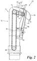
- FIG. 2 there is shown in schematic form a grain elevator 10 according to the invention, having associated therewith a mass flow measuring apparatus 20 of the general kind disclosed in European Patent Application No. 96201889.1.
- Mass flow measuring apparatus 20 is secured at the outlet 16 of housing 11.
- Measuring apparatus 20 includes sensor member 55 having sensor surface 53.
- Sensor member 55 is mounted for pivoting movement about pivot point P by virtue of support arm 60.
- a displacement sensor 52,69 senses displacement of sensor member 55 relative to e.g. outlet 16 and generates a signal proportional thereto.
- the displacements of sensor member 55 are proportional to the moments about pivot P generated by the flow of grain along surface 53. The moment at any given instant is proportional to the contemporaneous mass flow rate of grain.
- the base of the bubble up auger is located beneath the outlet area of sensor member 55 indicated generally by reference numeral 45.
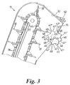
- FIGs 2 and 3 show an impeller in the form of a star wheel 47, mounted for rotation about a shaft 80, at the base of outlet portion 16 of housing 11.
- star wheel 47 comprises a series of material engaging portions each including a surface 47'.
- Star wheel 47 substantially spans the width of outlet 16.
- shaft 80 is drivingly engaged with a sprocket 81 driven by endless chain 48 that is wrapped around further sprocket 24, aligned with and laterally spaced from sprocket 23 at the top of grain elevator 10.
- Sprocket 23 is mounted on a common shaft with a further sprocket (not visible in Figure 2) for co-rotation therewith. Sprocket 23 is driven at a constant speed by virtue of further endless chain 39 extending in a longitudinal loop within elevator 10. The lower end of chain 39 is drivingly wrapped around yet a further sprocket 82 driven at a constant speed by the engine of the combine harvester.
- Sprocket 82 also provides drive to a further endless chain 36 on which the paddles 32 best shown in Figure 3 are mounted for movement within the grain elevator 10.
- the sizes of the various sprockets are chosen to ensure that the speed of the outer, peripheral portion 47'' of each surface 47' of star wheel 47 is matched to the speed of the outer portion of each paddle 32 as it passes around sprocket 23 at the top of grain elevator 10 and discharges grain towards outlet 16.
- each surface 47' is a circle.
- Each surface 47' is permanently at an angle to the line of the locus of the impeller.
- the angle of inclination of each surface 47' to the locus is chosen such that a particle of bulk material at any point on a surface 47' moves under centrifugal force towards the peripheral zone 47'' when the star wheel 47 rotates at the speed of the paddles 32.
- the angle of inclination of surface 47' is such that virtually all grains landing on each surface 47' reach the peripheral zone 47'' within a few degrees of rotation of star wheel 47. Thus such grains are projected clear of the star wheel 47 towards aperture 16, where they join the majority of grains previously projected from the paddles 32.
- a wall 48 interconnects each peripheral zone 47'' and the root zone 49 of the rearwardly adjacent surface 47'.
- Wall 48 is inclined to the locus of the wall 47' at a complementary angle to that of the wall 47', thereby completing the star wheel profile visible in Figure 3.
- grains of bulk material that fall onto the walls 48 are accelerated to the root zones 49 of the star wheel from where they experience centrifugal forces that drive them to the peripheral zones 47'' for projection towards outlet 16.
- the wall of housing 11 adjacent outlet 16 defines a guide surface 30 for the grains of bulk material projected from the paddles 32 and the star wheel 47.
- the location of shaft 80, and the diameter of star wheel 47, are chosen such that the space between the peripheral zones 47'' of the guide surface 30 is large enough to permit free, unchoked flow of granular material through outlet 16 yet sufficiently small to ensure that grains projected from the peripheral portions 47'' join the main bulk of the flow through outlet 16.
- the impeller is shown as star wheel 47 in Figure 3, other shapes are possible. Also, of course, the loci of the surfaces 47' need not be circular. It is sufficient simply for the inclination of each surface 47' relative to the locus to be such as to cause grains of bulk material on the surfaces 47' (or if present, on the walls 48) to travel to the peripheral zones 47'' for projection when the impeller 47 is driven at a predetermined speed.
- Figure 2 shows schematically (in dotted lines) a radar Doppler effect speed sensor for sensing the speed of granular material ejected from the paddles 32.
- the Doppler effect sensor 82 includes an emitter-receiver capable of transmitting a signal to the bulk material in the vicinity of the upper end of elevator 10 and receiving a wavelength-shifted signal reflected from the bulk material, the shifting of the wavelength of the signal being proportional to the speed of bulk material on the conveyor.
- radar Doppler effect sensor Numerous forms of radar Doppler effect sensor are known. These include sensors that generate an output signal proportional to the shifting of the wavelength, and hence proportional to the speed of the bulk material.
- the speed sensor 82 may include a signal generator and/or a signal processor for generating a signal indicative of the speed of the bulk material .
- This signal may be input to a processor as the initial speed of bulk material on the surface 53 of sensor member 55, whereby to permit calculation of the mass flow rate of bulk material.
- radar Doppler effect speed sensor 82 may alternatively be mounted on the outer side of housing 11 as indicated by reference numeral 82', adjacent a window 83 through which the measuring signal of the sensor may be projected and received after reflection.
- This arrangement is particularly suitable for optical Doppler effect devices.
- the window 83 would be effectively self-cleaning, by virtue of the repeated contact of grains therewith. Therefore the problem of dirt clogging the optical sensing devices known in the prior art can be eliminated.
- Figure 2 also shows one form of device for compensating for the effect on the magnitude of the force, moment or torque experienced by the sensor member 55 of inclination of the surface 53 of sensor member 55 from a predetermined orientation.
- This compensation means takes the form of counterweight 65 that lies at the free end of an extension of support arm 60 of sensor member 55.
- the extension projects beyond pivot point P so that counterweight 65 provides a moment about pivot point P acting to attenuate perturbations of sensor member 55.
- the counterweight 65 serves to displace the centre of gravity of the sensor member from the pivot axis P.
- an inclinometer shown schematically at 84 in Figure 2 may be employed.
- the inclinometer 84 can be located at any point that moves with the sensor member 55, in order to measure the inclination of sensor member 55 in at least one direction, from a predetermined, initial orientation.
- the inclinometer 84 generates a signal proportional to the inclination of sensor member 55. This signal may be fed to the processor calculating the mass flow rate of material on the sensor member 55, in order to correct the measured flow rate signal for inclination.
- Both embodiments of means for correcting the measured flow rate signal for inclination correct for changes in the inclination in the left to right (or right to left) direction of Figure 2. It is believed that orientation changes in this direction are likely to have the most significant effect on the measured flow rate values.
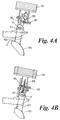
- Figures 4a to 4d show further embodiments of the mass flow measuring apparatus of Figure 2, in which the pivot point P is in each case disposed above the sensor member 53 via a suspension member 60.
- a shaft 61 extends to either side of pivot point P and engages a fixed part of the combine harvester for pivotable supporting of sensor member 55.
- Member 60 extends upwardly above pivot point P to support counterweight 65 that in the Figure 4 embodiments lies above pivot point P in order to counteract the effects of changes in the inclination of sensor member 55.
- Each of the embodiments of Figures 4a-4d includes means for calibrating the mass flow measuring apparatus.
- a calibration spring 86 interconnecting the support member 60 and a point fixed relative to surface 30.
- a linear solenoid actuator 87 is connected in series with the calibration spring such that on operation of actuator 87 calibration spring is moved into contact with a housing wall 88 so that spring 86 applies a known, predetermined force and moment or torque to support member 60.
- sensor member 55 This causes deflection of sensor member 55.
- deflection of sensor member 55 is detectable e.g. by means of sensor 52 ( Figure 2). Since the force applied by solenoid 87 and spring 86 is of a known magnitude, it may be used for calibration of the apparatus in a per se known manner once a second calibration reading is obtained, as described below.
- a second calibration reading of sensor 52 may be obtained by switching off the calibration solenoid 87 so that the sensor 52 detects the position of the sensor member 55 in the no flow condition. This may be regarded as the deflection equivalent to a zero mass flow rate in the sensor member 55.
- the two resulting calibration points may then be used, e.g. in a processor to ascribe the real time readings from sensor 52 to known mass flow rate values.
- a spring 86 alone may be employed, as shown in Figure 4c.
- the application of a force from this spring involves manual intervention by pulling on actuator member 89 and therefore this arrangement is primarily suited to calibration of the mass flow measuring apparatus during its construction or assembly.
- FIG. 4d A further possibility is shown in Figure 4d, in which an annular coil extends about shaft 61 the motor effect of which applies a known torque to shaft 61, thereby causing a deflection of sensor member 55 equivalent to a chosen mass flow rate.
- shaft 61 inside the annulus of coil 87 is of asymmetric cross section so that the coil torque tends to rotate the shaft.
Landscapes
- Physics & Mathematics (AREA)
- Fluid Mechanics (AREA)
- General Physics & Mathematics (AREA)
- Life Sciences & Earth Sciences (AREA)
- Environmental Sciences (AREA)
- Electromagnetism (AREA)
- Measuring Volume Flow (AREA)
Applications Claiming Priority (2)
| Application Number | Priority Date | Filing Date | Title |
|---|---|---|---|
| GB9700656 | 1997-01-14 | ||
| GB9700656A GB2321112A (en) | 1997-01-14 | 1997-01-14 | Impeller for mass flow measurement |
Publications (3)
| Publication Number | Publication Date |
|---|---|
| EP0856723A2 true EP0856723A2 (de) | 1998-08-05 |
| EP0856723A3 EP0856723A3 (de) | 1998-09-30 |
| EP0856723B1 EP0856723B1 (de) | 2013-04-03 |
Family
ID=10805946
Family Applications (1)
| Application Number | Title | Priority Date | Filing Date |
|---|---|---|---|
| EP97308677A Expired - Lifetime EP0856723B1 (de) | 1997-01-14 | 1997-10-30 | Massendurchfluss-Messgerät für einen Mähdrescher |
Country Status (3)
| Country | Link |
|---|---|
| US (1) | US6138518A (de) |
| EP (1) | EP0856723B1 (de) |
| GB (1) | GB2321112A (de) |
Cited By (7)
| Publication number | Priority date | Publication date | Assignee | Title |
|---|---|---|---|---|
| DE19802756B4 (de) * | 1998-01-26 | 2004-04-22 | Claas Selbstfahrende Erntemaschinen Gmbh | Fördervolumen-Meßvorrichtung eines Elevators, insbes. für Erntegut |
| EP1652421A1 (de) | 2004-10-30 | 2006-05-03 | Deere & Company | Erntemaschine mit einer Messeinrichtung zur Erfassung des Durchsatzes aufgenommenen und/oder bearbeiteten Ernteguts |
| EP1254351A4 (de) * | 1999-12-29 | 2006-07-05 | Hugo Gabriel Martina | MASSENDURCHFLUSS-MESSGERäT FüR PULVER UND GRANULATE UND AGGLOMERIERTE MASSEN. |
| WO2008080802A1 (de) * | 2006-12-29 | 2008-07-10 | Endress+Hauser Flowtec Ag | Verfahren zum inbetriebnehmen und/oder überwachen eines in-line-messgeräts |
| US7430845B2 (en) | 2005-12-14 | 2008-10-07 | Deere & Company | Harvesting machine with a measuring device for capturing the throughput of collected crop material |
| CN103688654A (zh) * | 2013-12-05 | 2014-04-02 | 广西科技大学 | 一种联合收割机的谷物流量测量装置 |
| EP3369300A1 (de) * | 2010-12-22 | 2018-09-05 | Precision Planting LLC | Verfahren, systeme und vorrichtung zur überwachung des ernteertrags und des fahrzeugs |
Families Citing this family (21)
| Publication number | Priority date | Publication date | Assignee | Title |
|---|---|---|---|---|
| US6431981B1 (en) * | 1999-06-30 | 2002-08-13 | Wisconsin Alumni Research Foundation | Yield monitor for forage crops |
| EP1187472B1 (de) * | 2000-02-07 | 2019-04-03 | Sony Corporation | Bildverarbeiter, bildverarbeitungsverfahren und datenträger |
| GB2364288A (en) * | 2000-07-05 | 2002-01-23 | Ford New Holland Nv | Elevator for bulk material and related apparatus |
| DE10253078B3 (de) * | 2002-11-13 | 2004-04-15 | Schenck Process Gmbh | Meßvorrichtung zur Ermittlung der Durchsatzmenge eines Massestromes |
| US6899616B1 (en) | 2003-12-23 | 2005-05-31 | Acoo Corporation | Mass flow grain monitor and method |
| US7222029B2 (en) * | 2004-07-08 | 2007-05-22 | Celerity, Inc. | Attitude insensitive flow device system and method |
| US7409871B2 (en) | 2006-03-16 | 2008-08-12 | Celerity, Inc. | Mass flow meter or controller with inclination sensor |
| CN103125204B (zh) * | 2011-12-03 | 2015-08-19 | 中国科学院合肥物质科学研究院 | 一种联合收割机的谷物质量测量装置与测量方法 |
| US9372109B2 (en) * | 2013-03-15 | 2016-06-21 | Raven Industires, Inc. | Harvester elevator in-flow weight sensor and methods for the same |
| US9410840B2 (en) | 2013-03-15 | 2016-08-09 | Raven Industries, Inc. | Multi-variable yield monitor and methods for the same |
| US9310329B2 (en) | 2013-03-15 | 2016-04-12 | Raven Industries, Inc. | Remote moisture sensor and methods for the same |
| NL2014592B1 (en) * | 2015-04-08 | 2017-01-19 | Forage Innovations Bv | Agricultural harvester with a measuring device behind a window and crop material processing method. |
| US9676557B2 (en) * | 2015-09-30 | 2017-06-13 | Deere & Company | Elevator paddle design to optimize sample bypass collection |
| CN106856808A (zh) * | 2015-12-11 | 2017-06-20 | 中国科学院沈阳自动化研究所 | 联合收割机谷物流量检测装置和测量方法 |
| DE102016118559A1 (de) | 2016-09-29 | 2018-03-29 | Claas Selbstfahrende Erntemaschinen Gmbh | Verfahren zur Bestimmung eines aus Schüttgut bestehenden Massenstroms |
| US20180249634A1 (en) * | 2017-03-06 | 2018-09-06 | Jason Morris | Peanut harvester |
| US10820503B2 (en) * | 2017-09-15 | 2020-11-03 | Deere & Company | Monitoring device for monitoring crop yield |
| US10716256B2 (en) * | 2017-09-15 | 2020-07-21 | Deere & Company | Sensor system for determining crop yield |
| GB201820713D0 (en) * | 2018-12-19 | 2019-01-30 | Agco Int Gmbh | Grain cleaning system and method of controlling such |
| DE102020110799A1 (de) * | 2020-04-21 | 2021-10-21 | Claas Selbstfahrende Erntemaschinen Gmbh | Verfahren zur Bestimmung eines aus Schüttgut bestehenden Gutstroms |
| DE102021112495A1 (de) * | 2021-05-12 | 2022-11-17 | Iwis Antriebssysteme Gmbh & Co. Kg | Kornförderkette |
Citations (3)
| Publication number | Priority date | Publication date | Assignee | Title |
|---|---|---|---|---|
| US3888389A (en) | 1972-08-23 | 1975-06-10 | Buehler Ag Geb | Flow controller for flowing products, more particularly, bulk materials |
| EP0208025A1 (de) | 1985-07-12 | 1987-01-14 | Ford New Holland N.V. | Strömungsmesseinrichtung |
| WO1996038714A1 (en) | 1995-06-02 | 1996-12-05 | Dronningborg Industries A/S | A method of determining the mass flow of a flow of grains |
Family Cites Families (20)
| Publication number | Priority date | Publication date | Assignee | Title |
|---|---|---|---|---|
| GB612829A (en) * | 1946-01-07 | 1948-11-18 | Henry Joel Hamblin | Improvements in or relating to elevators |
| GB1015094A (en) * | 1962-12-21 | 1965-12-31 | Baker Perkins Ltd | Improvements in or relating to rotary feeding devices for particulate material |
| GB1254443A (en) * | 1968-09-12 | 1971-11-24 | James Scott Electronic Enginee | Radar systems |
| GB1323285A (en) * | 1971-05-10 | 1973-07-11 | Rothmans Of Pall Mall | Package manipulating apparatus |
| US4081074A (en) * | 1976-03-22 | 1978-03-28 | Stone Paul A | Bulk material dispensing device |
| GB1572755A (en) * | 1977-08-15 | 1980-08-06 | Inst Gornogo Dela Sibirskogo O | Rotary pocket feeders for materials |
| US4148027A (en) * | 1978-03-27 | 1979-04-03 | Rca Corporation | Surface roughness measuring apparatus |
| FR2473230A1 (fr) * | 1980-01-04 | 1981-07-10 | Thomson Csf | Generateur de signaux electriques a puissance elevee |
| FR2491210A1 (fr) * | 1980-09-30 | 1982-04-02 | Perret Bertrand | Dispositif de pesage en continu de produits granuleux en mouvement |
| DE3500944C1 (de) * | 1985-01-14 | 1986-08-14 | Technical Development Corp., Wetzikon | Vorrichtung zum Ausrichten von zum Schneiden bestimmten Tabakblättern |
| US4768387A (en) * | 1987-05-13 | 1988-09-06 | Milltronics, Inc. | Flowmeter |
| DE4028141C2 (de) * | 1990-09-04 | 1994-07-14 | Atz Evus | Vorrichtung zur Messung eines vorzugsweise mehrphasigen Masse-Stromes |
| WO1992008958A1 (en) * | 1990-11-14 | 1992-05-29 | Giles Alan F | Particle weighing apparatus and method |
| US5343761A (en) * | 1991-06-17 | 1994-09-06 | Allen Myers | Method and apparatus for measuring grain mass flow rate in harvesters |
| US5594667A (en) * | 1992-07-10 | 1997-01-14 | Myers; Allen | Method and apparatus for baseline drift correction for a sensor |
| US5369603A (en) * | 1992-07-19 | 1994-11-29 | Myers; Allen | Calibration of a non-linear sensor |
| US5550537A (en) * | 1994-05-06 | 1996-08-27 | Endress + Hauser, Inc. | Apparatus and method for measuring mass flow rate of a moving medium |
| GB2303457A (en) * | 1995-07-14 | 1997-02-19 | New Holland Belguim Nv | Mass flow metering device |
| US5798466A (en) * | 1996-01-26 | 1998-08-25 | Satake Corporation | Flow meter and method of calibrating same |
| GB2321111A (en) * | 1997-01-11 | 1998-07-15 | Ford New Holland Nv | Member for mass flow measurement |
-
1997
- 1997-01-14 GB GB9700656A patent/GB2321112A/en not_active Withdrawn
- 1997-10-30 EP EP97308677A patent/EP0856723B1/de not_active Expired - Lifetime
-
1998
- 1998-01-09 US US09/005,095 patent/US6138518A/en not_active Expired - Lifetime
Patent Citations (3)
| Publication number | Priority date | Publication date | Assignee | Title |
|---|---|---|---|---|
| US3888389A (en) | 1972-08-23 | 1975-06-10 | Buehler Ag Geb | Flow controller for flowing products, more particularly, bulk materials |
| EP0208025A1 (de) | 1985-07-12 | 1987-01-14 | Ford New Holland N.V. | Strömungsmesseinrichtung |
| WO1996038714A1 (en) | 1995-06-02 | 1996-12-05 | Dronningborg Industries A/S | A method of determining the mass flow of a flow of grains |
Cited By (9)
| Publication number | Priority date | Publication date | Assignee | Title |
|---|---|---|---|---|
| DE19802756B4 (de) * | 1998-01-26 | 2004-04-22 | Claas Selbstfahrende Erntemaschinen Gmbh | Fördervolumen-Meßvorrichtung eines Elevators, insbes. für Erntegut |
| EP1254351A4 (de) * | 1999-12-29 | 2006-07-05 | Hugo Gabriel Martina | MASSENDURCHFLUSS-MESSGERäT FüR PULVER UND GRANULATE UND AGGLOMERIERTE MASSEN. |
| EP1652421A1 (de) | 2004-10-30 | 2006-05-03 | Deere & Company | Erntemaschine mit einer Messeinrichtung zur Erfassung des Durchsatzes aufgenommenen und/oder bearbeiteten Ernteguts |
| US7430845B2 (en) | 2005-12-14 | 2008-10-07 | Deere & Company | Harvesting machine with a measuring device for capturing the throughput of collected crop material |
| WO2008080802A1 (de) * | 2006-12-29 | 2008-07-10 | Endress+Hauser Flowtec Ag | Verfahren zum inbetriebnehmen und/oder überwachen eines in-line-messgeräts |
| DE102006062600B4 (de) | 2006-12-29 | 2023-12-21 | Endress + Hauser Flowtec Ag | Verfahren zum Inbetriebnehmen und/oder Überwachen eines In-Line-Meßgeräts |
| EP3369300A1 (de) * | 2010-12-22 | 2018-09-05 | Precision Planting LLC | Verfahren, systeme und vorrichtung zur überwachung des ernteertrags und des fahrzeugs |
| US10420278B2 (en) | 2010-12-22 | 2019-09-24 | Precision Planting Llc | Methods, systems, and apparatus for monitoring yield and vehicle weight |
| CN103688654A (zh) * | 2013-12-05 | 2014-04-02 | 广西科技大学 | 一种联合收割机的谷物流量测量装置 |
Also Published As
| Publication number | Publication date |
|---|---|
| GB2321112A (en) | 1998-07-15 |
| US6138518A (en) | 2000-10-31 |
| EP0856723B1 (de) | 2013-04-03 |
| EP0856723A3 (de) | 1998-09-30 |
| GB9700656D0 (en) | 1997-03-05 |
Similar Documents
| Publication | Publication Date | Title |
|---|---|---|
| US6138518A (en) | Mass flow measurement | |
| US6272935B1 (en) | Apparatus for mass flow measurement | |
| US5959218A (en) | Method and device for measuring the flow of bulk materials | |
| EP1333253B1 (de) | Massenströmungsmessungsvorrichtung | |
| RU2487319C2 (ru) | Устройство измерения для определения массового расхода убираемых культур | |
| US5863247A (en) | Method of measuring harvested product quantity in elevator of harvester | |
| US6584424B2 (en) | Yield monitoring system for grain harvesting combine | |
| EP0208025A1 (de) | Strömungsmesseinrichtung | |
| US7584696B2 (en) | Agricultural balers | |
| US6282967B1 (en) | Apparatus for measuring the throughput of material on a conveyer | |
| EP0056515A2 (de) | Transportmitteleichungsverfahren | |
| DK2748568T3 (en) | Self-calibrating dosing device | |
| BRPI0912795B1 (pt) | sistema de monitoramento e método para monitorar um nível de depósito para um produto agrícola | |
| CA3086857A1 (en) | Proppant metering and loading in a hydraulic fracturing blender | |
| US5970802A (en) | Relating to mass flow measuring apparatuses | |
| US5594667A (en) | Method and apparatus for baseline drift correction for a sensor | |
| AU2019313596B2 (en) | Intake arrangement for a roller mill, roller mill having such an intake arrangement and method for determining the ground material fill level of a storage container of a roller mill | |
| US6237427B1 (en) | Flow rate measuring system for crops supported on a conveyor | |
| CN108347883B (zh) | 联合收割机以及联合收割机用谷粒产量管理系统 | |
| US6814108B1 (en) | Precision filling apparatus | |
| US5952584A (en) | Friction-independent mass flow meter | |
| WO2021001675A1 (en) | Continuous mobile concrete dispenser with a weight control | |
| EP1205737A2 (de) | Anordnung von Geräten zur Massen-Durchflussmessung | |
| JPH08228681A (ja) | 製茶ラインにおける生茶葉サンプリング計測構造 | |
| CN109733899A (zh) | 铸件检测计量系统及其控制方法 |
Legal Events
| Date | Code | Title | Description |
|---|---|---|---|
| PUAI | Public reference made under article 153(3) epc to a published international application that has entered the european phase |
Free format text: ORIGINAL CODE: 0009012 |
|
| AK | Designated contracting states |
Kind code of ref document: A2 Designated state(s): DE DK FR GB |
|
| AX | Request for extension of the european patent |
Free format text: AL;LT;LV;RO;SI |
|
| PUAL | Search report despatched |
Free format text: ORIGINAL CODE: 0009013 |
|
| AK | Designated contracting states |
Kind code of ref document: A3 Designated state(s): AT BE CH DE DK ES FI FR GB GR IE IT LI LU MC NL PT SE |
|
| AX | Request for extension of the european patent |
Free format text: AL;LT;LV;RO;SI |
|
| 17P | Request for examination filed |
Effective date: 19990325 |
|
| AKX | Designation fees paid |
Free format text: DE DK FR GB |
|
| RAP1 | Party data changed (applicant data changed or rights of an application transferred) |
Owner name: CNH BELGIUM N.V. |
|
| RTI1 | Title (correction) |
Free format text: MASS FLOW MEASURING APPARATUS FOR A COMBINE HARVESTER |
|
| GRAP | Despatch of communication of intention to grant a patent |
Free format text: ORIGINAL CODE: EPIDOSNIGR1 |
|
| GRAS | Grant fee paid |
Free format text: ORIGINAL CODE: EPIDOSNIGR3 |
|
| GRAA | (expected) grant |
Free format text: ORIGINAL CODE: 0009210 |
|
| AK | Designated contracting states |
Kind code of ref document: B1 Designated state(s): DE DK FR GB |
|
| REG | Reference to a national code |
Ref country code: GB Ref legal event code: FG4D |
|
| REG | Reference to a national code |
Ref country code: DE Ref legal event code: R096 Ref document number: 69740574 Country of ref document: DE Effective date: 20130529 |
|
| PG25 | Lapsed in a contracting state [announced via postgrant information from national office to epo] |
Ref country code: DK Free format text: LAPSE BECAUSE OF FAILURE TO SUBMIT A TRANSLATION OF THE DESCRIPTION OR TO PAY THE FEE WITHIN THE PRESCRIBED TIME-LIMIT Effective date: 20130403 |
|
| PLBE | No opposition filed within time limit |
Free format text: ORIGINAL CODE: 0009261 |
|
| STAA | Information on the status of an ep patent application or granted ep patent |
Free format text: STATUS: NO OPPOSITION FILED WITHIN TIME LIMIT |
|
| 26N | No opposition filed |
Effective date: 20140106 |
|
| REG | Reference to a national code |
Ref country code: DE Ref legal event code: R097 Ref document number: 69740574 Country of ref document: DE Effective date: 20140106 |
|
| REG | Reference to a national code |
Ref country code: DE Ref legal event code: R082 Ref document number: 69740574 Country of ref document: DE Representative=s name: PATENTANWAELTE WALLACH, KOCH & PARTNER, DE |
|
| REG | Reference to a national code |
Ref country code: DE Ref legal event code: R082 Ref document number: 69740574 Country of ref document: DE Representative=s name: PATENTANWAELTE WALLACH, KOCH, DR. HAIBACH, FEL, DE Effective date: 20140519 Ref country code: DE Ref legal event code: R082 Ref document number: 69740574 Country of ref document: DE Representative=s name: PATENTANWAELTE WALLACH, KOCH & PARTNER, DE Effective date: 20140519 Ref country code: DE Ref legal event code: R081 Ref document number: 69740574 Country of ref document: DE Owner name: CNH INDUSTRIAL BELGIUM NV, BE Free format text: FORMER OWNER: NEW HOLLAND BELGIUM N.V., ZEDELGEM, BE Effective date: 20130303 Ref country code: DE Ref legal event code: R081 Ref document number: 69740574 Country of ref document: DE Owner name: CNH INDUSTRIAL BELGIUM NV, BE Free format text: FORMER OWNER: CNH BELGIUM N.V., ZEDELGEM, BE Effective date: 20140519 |
|
| REG | Reference to a national code |
Ref country code: FR Ref legal event code: CD Owner name: CNH INDUSTRIAL BELGIUM NV Effective date: 20140725 |
|
| REG | Reference to a national code |
Ref country code: DE Ref legal event code: R084 Ref document number: 69740574 Country of ref document: DE |
|
| REG | Reference to a national code |
Ref country code: GB Ref legal event code: 746 Effective date: 20141008 |
|
| REG | Reference to a national code |
Ref country code: DE Ref legal event code: R084 Ref document number: 69740574 Country of ref document: DE Effective date: 20140927 |
|
| PGFP | Annual fee paid to national office [announced via postgrant information from national office to epo] |
Ref country code: FR Payment date: 20141007 Year of fee payment: 18 |
|
| PGFP | Annual fee paid to national office [announced via postgrant information from national office to epo] |
Ref country code: GB Payment date: 20151008 Year of fee payment: 19 Ref country code: DE Payment date: 20151009 Year of fee payment: 19 |
|
| REG | Reference to a national code |
Ref country code: FR Ref legal event code: ST Effective date: 20160630 |
|
| PG25 | Lapsed in a contracting state [announced via postgrant information from national office to epo] |
Ref country code: FR Free format text: LAPSE BECAUSE OF NON-PAYMENT OF DUE FEES Effective date: 20151102 |
|
| REG | Reference to a national code |
Ref country code: DE Ref legal event code: R119 Ref document number: 69740574 Country of ref document: DE |
|
| GBPC | Gb: european patent ceased through non-payment of renewal fee |
Effective date: 20161030 |
|
| PG25 | Lapsed in a contracting state [announced via postgrant information from national office to epo] |
Ref country code: DE Free format text: LAPSE BECAUSE OF NON-PAYMENT OF DUE FEES Effective date: 20170503 Ref country code: GB Free format text: LAPSE BECAUSE OF NON-PAYMENT OF DUE FEES Effective date: 20161030 |