EP0856764A2 - Dispositif optique à lentilles à gradient d'indice de refraction - Google Patents
Dispositif optique à lentilles à gradient d'indice de refraction Download PDFInfo
- Publication number
- EP0856764A2 EP0856764A2 EP98101281A EP98101281A EP0856764A2 EP 0856764 A2 EP0856764 A2 EP 0856764A2 EP 98101281 A EP98101281 A EP 98101281A EP 98101281 A EP98101281 A EP 98101281A EP 0856764 A2 EP0856764 A2 EP 0856764A2
- Authority
- EP
- European Patent Office
- Prior art keywords
- grin lens
- grin
- optical
- lenses
- optical device
- Prior art date
- Legal status (The legal status is an assumption and is not a legal conclusion. Google has not performed a legal analysis and makes no representation as to the accuracy of the status listed.)
- Withdrawn
Links
- 230000003287 optical effect Effects 0.000 title claims abstract description 70
- 230000001419 dependent effect Effects 0.000 claims description 4
- 238000001914 filtration Methods 0.000 abstract description 5
- 239000011248 coating agent Substances 0.000 description 9
- 238000000576 coating method Methods 0.000 description 9
- 238000010586 diagram Methods 0.000 description 6
- 239000010409 thin film Substances 0.000 description 4
- 230000008878 coupling Effects 0.000 description 3
- 238000010168 coupling process Methods 0.000 description 3
- 238000005859 coupling reaction Methods 0.000 description 3
- 239000002131 composite material Substances 0.000 description 2
- 238000000034 method Methods 0.000 description 2
- 239000013307 optical fiber Substances 0.000 description 2
- 239000000758 substrate Substances 0.000 description 2
- 230000005540 biological transmission Effects 0.000 description 1
- 238000010276 construction Methods 0.000 description 1
- 230000000694 effects Effects 0.000 description 1
- 238000009501 film coating Methods 0.000 description 1
- 238000004519 manufacturing process Methods 0.000 description 1
- 238000010079 rubber tapping Methods 0.000 description 1
Images



Classifications
-
- G—PHYSICS
- G02—OPTICS
- G02B—OPTICAL ELEMENTS, SYSTEMS OR APPARATUS
- G02B6/00—Light guides; Structural details of arrangements comprising light guides and other optical elements, e.g. couplings
- G02B6/24—Coupling light guides
- G02B6/26—Optical coupling means
- G02B6/28—Optical coupling means having data bus means, i.e. plural waveguides interconnected and providing an inherently bidirectional system by mixing and splitting signals
- G02B6/293—Optical coupling means having data bus means, i.e. plural waveguides interconnected and providing an inherently bidirectional system by mixing and splitting signals with wavelength selective means
- G02B6/29346—Optical coupling means having data bus means, i.e. plural waveguides interconnected and providing an inherently bidirectional system by mixing and splitting signals with wavelength selective means operating by wave or beam interference
- G02B6/29361—Interference filters, e.g. multilayer coatings, thin film filters, dichroic splitters or mirrors based on multilayers, WDM filters
- G02B6/2937—In line lens-filtering-lens devices, i.e. elements arranged along a line and mountable in a cylindrical package for compactness, e.g. 3- port device with GRIN lenses sandwiching a single filter operating at normal incidence in a tubular package
-
- G—PHYSICS
- G02—OPTICS
- G02B—OPTICAL ELEMENTS, SYSTEMS OR APPARATUS
- G02B6/00—Light guides; Structural details of arrangements comprising light guides and other optical elements, e.g. couplings
- G02B6/24—Coupling light guides
- G02B6/26—Optical coupling means
- G02B6/28—Optical coupling means having data bus means, i.e. plural waveguides interconnected and providing an inherently bidirectional system by mixing and splitting signals
- G02B6/293—Optical coupling means having data bus means, i.e. plural waveguides interconnected and providing an inherently bidirectional system by mixing and splitting signals with wavelength selective means
- G02B6/29379—Optical coupling means having data bus means, i.e. plural waveguides interconnected and providing an inherently bidirectional system by mixing and splitting signals with wavelength selective means characterised by the function or use of the complete device
- G02B6/29389—Bandpass filtering, e.g. 1x1 device rejecting or passing certain wavelengths
Definitions
- This invention relates generally to the coupling of light through graded index lenses and more particularly in one embodiment to a device that provides multi-pass filtering through a same filter element.
- WDM filters are WDM filter element typically comprising a multi-layered thin film structure deposited on a transparent substrate, between two, quarter-pitch graded index (GRIN) lenses. In some instances the thin film coating is applied to one of the end faces of the lens. Lenses of this type are produced under the trade name "SELFOC"; the mark is registered in Japan and owned by the Nippon Sheet and Glass Co. Ltd.
- each GRIN lens is provided with a port which is a point or region along an endface of the lens for receiving or transmitting a beam of light .
- WDM filters perform their intended function, filters having a sharper, steeper more square response are at times required.
- This desired response can be achieved by passing a beam through multiple, similar, cascaded filters; or alternatively, and less preferred, by sandwiching two WDM filter elements together. The latter solution is however difficult to manufacture and tends not be a reliable design.
- an optical device directs an input beam launched into an input end thereof, to be directed out of a same end of the device at at least one of a different port and a different angle.
- light is launched into the device at a first angle with respect to the optical axis of the lens and exits from a same end face at a different angle.
- light is launched into the device at a first port at an input end face, and passes through an optical element within the device two times exiting at a second port on the input end face.
- At least two GRIN lenses are disposed in such a manner as to allow light to pass from one lens end face to the other, however the optical axes of the lenses being offset.
- One of the lenses has at or near its end face, an at least partially reflective coating to allow a predetermined amount of input light to reflect backwards toward the input end.
- the reflective coating is positioned in such a manner as to ensure light incident upon it is collimated.
- an optical device comprising: a first GRIN lens having a focusing end and a substantially collimating end, the focusing end having at least three ports, at least one being an input port and at least one being an output port, a second GRIN lens having substantially collimating face and a substantially focusing end face, the substantially collimating face being at least partially reflective to reflect at least a portion of a predetermined wavelength of light to one of the at least one output port on the focusing end of the first GRIN lens; and, an optical element disposed between the substantially collimating end faces of the first and second GRIN lenses, the first and second GRIN lenses having optical axes which are offset.
- an optical device comprising:
- an optical device comprising: a WDM filter having two juxtaposed GRIN lenses and an filter element therebetween; and,
- an optical device comprising a first GRIN lens and a second GRIN lens having their optical axes offset, the first GRIN lens having at least an input port at an input end face thereof, the second GRIN lens being disposed to receive light from the first GRIN lens at a first end face thereof; an at least partially reflecting surface on or about a second end face of the second GRIN lens and positioned to reflect an input beam of light launched into the input end face of the first GRIN lens, the first and second GRIN lenses, and the at least partially reflecting surface positioned to substantially collimate the input beam at the reflecting surface.
- a pair of quarter pitch GRIN lenses 10a and 10b are shown having a dichroic filter 8 designed to reflect light of wavelength ⁇ 1 and to pass light of wavelength ⁇ 2, sandwiched between collimating end faces 14a and 14b of the lenses.
- An input port 12 and an output port 13 are provided at a focusing end face of the lens 10a; the lens 10b has an output port 16 at its focusing end face that is optically aligned with the input port 12.
- the meaning of the word port in the specification is understood to be a location at an end face of a GRIN lens where light is launched into the lens or received from the lens.
- Common dichroic filter elements typically comprise a pair of quarter pitch graded index (GRIN) lenses, either having one of their inside end faces coated with filter comprising a plurality of thin film layers, or have a transparent substrate, coated with thin film layers, disposed between the inwardly facing end faces of the pair of GRIN lenses.
- GRIN quarter pitch graded index
- a graph is shown of a wavelength versus amplitude transmission response for the filter 8 of Fig. 1.
- One method of improving the slope of the response of the filter in Fig. 1 is to repeat filtering the output at 16, a second time, thereby producing an output response as is shown in Fig. 4 which is considerably steeper. This is accomplished by passing the signal at 16 through a same filter again, and this is shown in Fig. 3.
- Output 16 of the first filter 30 is connected to input port 12 of the second filter 32 using conventional coupling means such as an optical fiber tube (not shown) to couple optical fiber to the GRIN lens.
- this cascaded device performs its intended function, the associated coupling losses are significant.
- this design requires four quarter pitch GRIN lenses and relatively expensive matched dichroic optical filters.
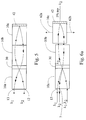
- FIG. 6a A preferred embodiment of the invention is shown in Fig. 6a wherein a third GRIN lens 10c, is optically coupled to the output port of the second GRIN lens 10b.
- the third GRIN lens has its outer end face coated with a reflective coating 42 to reflect light incident upon it.
- the first and second lenses 10a and 10b share a common optical axis
- the third GRIN lens 10c has its optical axis offset from that of the other two lenses. This is done so that light returning from the reflective coating 42 is directed to a third port 7, on the input end face of the first GRIN lens 10a.
- the location of the port 7 on the input end face of the lens 10a changes.
- the effect of moving lens 10c changes the beam angle launched into the collimated end of lens 10a which results in changing the position of the focus point (port 7) at the lens 10a.
- the reflective coating 42 is designed to pass 5% of light incident upon it, and thus provides a tap for tapping a portion of the signal ⁇ 2.
- a wavelength dependent filter can alternatively be provided for reflecting one or more wavelengths and passing one or more others. In operation, light of wavelength ⁇ 1 and ⁇ 2 is launched into an input port at an end of the lens 10a.
- the WDM filter 30 reflects the light of wavelength ⁇ 1 and passes light of wavelength ⁇ 2 shown by double arrows, which propagates through to the lenses 10b and 10c and is mostly reflected by the reflective coating 42 in a backwards direction along a different path and exits the end face of the lens 10a at port 7.
- the signal at port 7 of wavelength ⁇ 2 has passed through the filter 30 two times.
- the reflective coating 42 comprises a wavelength dependent coating in the form of a wavelength selective filter.
- the filter 30 is designed to reflect light of wavelength ⁇ 1 and pass light of wavelength ⁇ 2 and ⁇ 3.
- the filter 30 is designed to reflect light of wavelength ⁇ 1 and pass light of wavelength ⁇ 2 and ⁇ 3.
- light of wavelength ⁇ 1 is reflected, and light of wavelength ⁇ 2 and ⁇ 3 is passed and is directed to the wavelength selective filter 42.
- light of wavelength ⁇ 2 is reflected and light of wavelength ⁇ 3 is passed through the filter 42.
- light of wavelength ⁇ 3 can be launched into the end face of the filter 42 thereby adding a channel ⁇ 3.
- double filtering of light of wavelength ⁇ 2 is achieved.
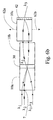
- Fig. 6b shows an embodiment similar to that of Fig. 6a, however no tap port is provided.
- the reflective element in this embodiment is a totally reflective mirror.
- Fig. 7b a similar embodiment to Fig. 6b is shown however the reflective element 42 is disposed near or adjacent the end face of the lens 10c, in such a manner as for light incident upon the element 42 to be collimated.
- Fig. 5 illustrates that if the optical axis of the third lens 10c is coaxial, an not offset from the axes of the other two lenses 10a and 10b, the twice filtered beam of wavelength ⁇ 2 will return along the same path from which it was launched, resulting in the twice filtered beam exiting on the input port 12.
- the twice filtered beam of wavelength ⁇ 2 is directed to the third port 7.
- a first GRIN lens 10a is optically coupled with a second GRIN lens 10b which has its optical axis offset from that of the first lens 10a.
- a reflective surface 42 which can be a discrete optical element at or about an end face of the lens 10b or a coating on the end face of the lens 10b is disposed at a position that will ensure that a beam of light incident upon the reflective surface 42 is substantially collimated.
- light launched into the input end face at a first angle ⁇ with respect to the optical axis of the lens 10a exits at a second different angle ⁇ from the end face of the lens 10a.
- angles ⁇ and ⁇ can be the same but the direction of light entering and exiting the end face is different.
- this provides a means of routing an optical signal incident upon the device from a first direction to a different location by directing the signal away from the device in a second direction.
- the reflective surface can be coated to allow a predetermined amount of light to pass therethrough thereby providing a tap.
Landscapes
- Physics & Mathematics (AREA)
- General Physics & Mathematics (AREA)
- Optics & Photonics (AREA)
- Optical Couplings Of Light Guides (AREA)
- Optical Filters (AREA)
Applications Claiming Priority (2)
| Application Number | Priority Date | Filing Date | Title |
|---|---|---|---|
| US791325 | 1985-10-25 | ||
| US08/791,325 US5790314A (en) | 1997-01-31 | 1997-01-31 | Grin lensed optical device |
Publications (2)
| Publication Number | Publication Date |
|---|---|
| EP0856764A2 true EP0856764A2 (fr) | 1998-08-05 |
| EP0856764A3 EP0856764A3 (fr) | 2000-05-24 |
Family
ID=25153371
Family Applications (1)
| Application Number | Title | Priority Date | Filing Date |
|---|---|---|---|
| EP98101281A Withdrawn EP0856764A3 (fr) | 1997-01-31 | 1998-01-26 | Dispositif optique à lentilles à gradient d'indice de refraction |
Country Status (4)
| Country | Link |
|---|---|
| US (1) | US5790314A (fr) |
| EP (1) | EP0856764A3 (fr) |
| JP (1) | JPH10311905A (fr) |
| CA (1) | CA2223667C (fr) |
Cited By (4)
| Publication number | Priority date | Publication date | Assignee | Title |
|---|---|---|---|---|
| EP1001288A1 (fr) * | 1997-10-07 | 2000-05-17 | IOT Integrierte Optik GmbH & Co. KG | Couplage de la lumière dans un dispositif de guide d'onde monolithique |
| EP1239314A1 (fr) * | 2001-03-08 | 2002-09-11 | Schott Glas | Montage filtre optique |
| KR100361441B1 (ko) * | 2000-06-02 | 2002-11-18 | 전자부품연구원 | 탭 커플러 |
| WO2007039765A1 (fr) * | 2005-10-06 | 2007-04-12 | Bookham Technology Plc | Composant optique d'aplanissement de gain de signaux wdm comprenant ledit composant et amplificateur optique |
Families Citing this family (71)
| Publication number | Priority date | Publication date | Assignee | Title |
|---|---|---|---|---|
| US7164818B2 (en) * | 2001-05-03 | 2007-01-16 | Neophontonics Corporation | Integrated gradient index lenses |
| US6125221A (en) * | 1998-03-19 | 2000-09-26 | Lucent Technologies, Inc. | Three port optical filter |
| US6055112A (en) * | 1998-04-24 | 2000-04-25 | Campbell-Miller; Margot | Lensed cascaded optical filter |
| US6215924B1 (en) | 1998-08-06 | 2001-04-10 | Optical Coating Laboratory, Inc. | Optical coupler device for dense wavelength division multiplexing |
| US6088166A (en) * | 1998-12-22 | 2000-07-11 | Dicon Fiberoptics, Inc. | Miniaturization of gradient index lens used in optical components |
| WO2000039626A1 (fr) | 1998-12-31 | 2000-07-06 | Optical Coating Laboratory, Inc. | Commutateur optique selectif a longueur d'onde |
| US6253005B1 (en) * | 1999-06-10 | 2001-06-26 | Agere Systems Optoelectronics Guardian Corp. | Apparatus and method for compensating for misalignment in reflective packages |
| US6433924B1 (en) | 2000-11-14 | 2002-08-13 | Optical Coating Laboratory, Inc. | Wavelength-selective optical amplifier |
| US6839517B2 (en) * | 2001-02-12 | 2005-01-04 | Agere Systems Inc. | Apparatus and method for transmitting optical signals through a single fiber optical network |
| US20020146203A1 (en) * | 2001-03-08 | 2002-10-10 | Burkhard Danielzik | Optical filter assembly |
| JP2003202450A (ja) * | 2001-12-28 | 2003-07-18 | Nippon Sheet Glass Co Ltd | コリメータアレイ |
| SE524401C2 (sv) * | 2002-05-17 | 2004-08-03 | Cobolt Ab | Arrangemang och metod för tillverkning av Grin-linser |
| KR20040016406A (ko) | 2002-08-15 | 2004-02-21 | 호야 가부시키가이샤 | 광 모듈 |
| CN100495096C (zh) * | 2004-05-26 | 2009-06-03 | Hoya株式会社 | 光模块和光波长合波分波装置 |
| WO2006051981A1 (fr) * | 2004-11-15 | 2006-05-18 | Hitachi Chemical Company, Ltd. | Reflecteur de lumiere, photocoupleur/filtre de derivation et systeme optique |
| JP3852709B2 (ja) * | 2005-01-31 | 2006-12-06 | 日立金属株式会社 | 光パワーモニターとその製造方法 |
| CN1870485B (zh) * | 2005-05-24 | 2010-05-26 | 亚洲光学股份有限公司 | 离轴式波长分割多工器 |
| GB0522968D0 (en) | 2005-11-11 | 2005-12-21 | Popovich Milan M | Holographic illumination device |
| GB0718706D0 (en) | 2007-09-25 | 2007-11-07 | Creative Physics Ltd | Method and apparatus for reducing laser speckle |
| US9335604B2 (en) | 2013-12-11 | 2016-05-10 | Milan Momcilo Popovich | Holographic waveguide display |
| US11726332B2 (en) | 2009-04-27 | 2023-08-15 | Digilens Inc. | Diffractive projection apparatus |
| US9274349B2 (en) | 2011-04-07 | 2016-03-01 | Digilens Inc. | Laser despeckler based on angular diversity |
| US10670876B2 (en) | 2011-08-24 | 2020-06-02 | Digilens Inc. | Waveguide laser illuminator incorporating a despeckler |
| EP2748670B1 (fr) | 2011-08-24 | 2015-11-18 | Rockwell Collins, Inc. | Affichage de données portable |
| WO2016020630A2 (fr) | 2014-08-08 | 2016-02-11 | Milan Momcilo Popovich | Illuminateur laser en guide d'ondes comprenant un dispositif de déchatoiement |
| US20150010265A1 (en) | 2012-01-06 | 2015-01-08 | Milan, Momcilo POPOVICH | Contact image sensor using switchable bragg gratings |
| EP2842003B1 (fr) | 2012-04-25 | 2019-02-27 | Rockwell Collins, Inc. | Affichage grand angle holographique |
| US9456744B2 (en) | 2012-05-11 | 2016-10-04 | Digilens, Inc. | Apparatus for eye tracking |
| US8774579B2 (en) | 2012-09-21 | 2014-07-08 | Corning Cable Systems Llc | Asymmetric multi-channel GRIN optical connector |
| US9933684B2 (en) | 2012-11-16 | 2018-04-03 | Rockwell Collins, Inc. | Transparent waveguide display providing upper and lower fields of view having a specific light output aperture configuration |
| US10209517B2 (en) | 2013-05-20 | 2019-02-19 | Digilens, Inc. | Holographic waveguide eye tracker |
| US9727772B2 (en) | 2013-07-31 | 2017-08-08 | Digilens, Inc. | Method and apparatus for contact image sensing |
| CA3028775C (fr) | 2014-03-04 | 2020-01-07 | Novadaq Technologies ULC | Ouvertures de filtrage spatial et spectral et systemes d'imagerie optique comportant lesdites ouvertures |
| CA2941273C (fr) * | 2014-03-04 | 2019-10-01 | Novadaq Technologies Inc. | Systeme de lentille de relais pour imagerie a large bande |
| WO2016020632A1 (fr) | 2014-08-08 | 2016-02-11 | Milan Momcilo Popovich | Procédé pour gravure par pressage et réplication holographique |
| WO2016042283A1 (fr) | 2014-09-19 | 2016-03-24 | Milan Momcilo Popovich | Procédé et appareil de production d'images d'entrée pour affichages à guides d'ondes holographiques |
| EP3198192A1 (fr) | 2014-09-26 | 2017-08-02 | Milan Momcilo Popovich | Dispositif de poursuite optique à guide d'ondes holographique |
| US10437064B2 (en) | 2015-01-12 | 2019-10-08 | Digilens Inc. | Environmentally isolated waveguide display |
| EP3245551B1 (fr) | 2015-01-12 | 2019-09-18 | DigiLens Inc. | Afficheurs à champ lumineux et à guide d'ondes |
| CN107533137A (zh) | 2015-01-20 | 2018-01-02 | 迪吉伦斯公司 | 全息波导激光雷达 |
| US9632226B2 (en) | 2015-02-12 | 2017-04-25 | Digilens Inc. | Waveguide grating device |
| WO2016146963A1 (fr) | 2015-03-16 | 2016-09-22 | Popovich, Milan, Momcilo | Dispositif de guide d'onde incorporant un conduit de lumière |
| US10591756B2 (en) | 2015-03-31 | 2020-03-17 | Digilens Inc. | Method and apparatus for contact image sensing |
| WO2017035646A1 (fr) | 2015-08-31 | 2017-03-09 | Novadaq Technologies Inc. | Filtre dépendant de la polarisation, système utilisant ledit filtre, kits et procédés associés |
| WO2017060665A1 (fr) | 2015-10-05 | 2017-04-13 | Milan Momcilo Popovich | Afficheur à guide d'ondes |
| EP3398007B1 (fr) | 2016-02-04 | 2024-09-11 | DigiLens, Inc. | Dispositif de poursuite optique de guide d'onde |
| JP6895451B2 (ja) | 2016-03-24 | 2021-06-30 | ディジレンズ インコーポレイテッド | 偏光選択ホログラフィー導波管デバイスを提供するための方法および装置 |
| EP3433658B1 (fr) | 2016-04-11 | 2023-08-09 | DigiLens, Inc. | Dispositif guide d'onde pour la projection de lumiere structuree |
| EP3548939A4 (fr) | 2016-12-02 | 2020-11-25 | DigiLens Inc. | Dispositif de guide d'ondes à éclairage de sortie uniforme |
| US10545346B2 (en) | 2017-01-05 | 2020-01-28 | Digilens Inc. | Wearable heads up displays |
| US10330868B2 (en) * | 2017-05-31 | 2019-06-25 | Alliance Fiber Optic Products, Inc. | Pluggable fiber loopback apparatus and methods for fiber optical systems |
| CN111386495B (zh) | 2017-10-16 | 2022-12-09 | 迪吉伦斯公司 | 用于倍增像素化显示器的图像分辨率的系统和方法 |
| JP7404243B2 (ja) | 2018-01-08 | 2023-12-25 | ディジレンズ インコーポレイテッド | 導波管セル内のホログラフィック格子の高スループット記録のためのシステムおよび方法 |
| JP7456929B2 (ja) | 2018-01-08 | 2024-03-27 | ディジレンズ インコーポレイテッド | 導波管セルを製造するためのシステムおよび方法 |
| CN114721242B (zh) | 2018-01-08 | 2025-08-15 | 迪吉伦斯公司 | 用于制造光学波导的方法 |
| WO2019136476A1 (fr) | 2018-01-08 | 2019-07-11 | Digilens, Inc. | Architectures de guides d'ondes et procédés de fabrication associés |
| US10690851B2 (en) | 2018-03-16 | 2020-06-23 | Digilens Inc. | Holographic waveguides incorporating birefringence control and methods for their fabrication |
| US11402801B2 (en) | 2018-07-25 | 2022-08-02 | Digilens Inc. | Systems and methods for fabricating a multilayer optical structure |
| WO2020149956A1 (fr) | 2019-01-14 | 2020-07-23 | Digilens Inc. | Affichage de guide d'ondes holographique avec couche de commande de lumière |
| US20200247017A1 (en) | 2019-02-05 | 2020-08-06 | Digilens Inc. | Methods for Compensating for Optical Surface Nonuniformity |
| US20220283377A1 (en) | 2019-02-15 | 2022-09-08 | Digilens Inc. | Wide Angle Waveguide Display |
| EP3924759B1 (fr) | 2019-02-15 | 2025-07-30 | Digilens Inc. | Procédés et appareils pour fournir un affichage de guide d'ondes holographique à l'aide de réseaux intégrés |
| JP2022525165A (ja) | 2019-03-12 | 2022-05-11 | ディジレンズ インコーポレイテッド | ホログラフィック導波管バックライトおよび関連する製造方法 |
| EP3980825A4 (fr) | 2019-06-07 | 2023-05-03 | Digilens Inc. | Guides d'ondes incorporant des réseaux transparents et réfléchissants et procédés de fabrication associés |
| JP2022543571A (ja) | 2019-07-29 | 2022-10-13 | ディジレンズ インコーポレイテッド | 画素化されたディスプレイの画像解像度および視野を乗算するための方法および装置 |
| JP2022546413A (ja) | 2019-08-29 | 2022-11-04 | ディジレンズ インコーポレイテッド | 真空回折格子および製造方法 |
| EP4252048A4 (fr) | 2020-12-21 | 2024-10-16 | Digilens Inc. | Suppression de la luminescence de l'oeil dans des affichages à base de guide d'ondes |
| WO2022150841A1 (fr) | 2021-01-07 | 2022-07-14 | Digilens Inc. | Structures de réseau pour guides d'ondes de couleur |
| KR20230153459A (ko) | 2021-03-05 | 2023-11-06 | 디지렌즈 인코포레이티드. | 진공 주기적 구조체 및 제조 방법 |
| US20250116876A1 (en) * | 2022-01-10 | 2025-04-10 | Edmund Optics, Inc. | Optical element with 3d gradient refractive index |
| CN118465928A (zh) * | 2023-02-08 | 2024-08-09 | 福州高意通讯有限公司 | 具有多个输入和输出的波分复用器 |
Family Cites Families (6)
| Publication number | Priority date | Publication date | Assignee | Title |
|---|---|---|---|---|
| US4504950A (en) * | 1982-03-02 | 1985-03-12 | California Institute Of Technology | Tunable graded rod laser assembly |
| US4550975A (en) * | 1982-04-29 | 1985-11-05 | At&T Bell Laboratories | Optical coupling devices |
| US4486071A (en) * | 1982-07-07 | 1984-12-04 | At&T Bell Laboratories | Optical coupling device |
| FR2532766B1 (fr) * | 1982-09-03 | 1985-08-02 | Western Electric Co | Dispositif de couplage optique |
| CA2146738C (fr) * | 1995-04-10 | 1999-09-14 | Y. Calvin Si | Filtre a bande etroite et methode de fabrication de ce filtre |
| US5539577A (en) * | 1995-05-16 | 1996-07-23 | Jds Fitel, Inc. | Means to lessen unwanted reflections in an optical device |
-
1997
- 1997-01-31 US US08/791,325 patent/US5790314A/en not_active Expired - Fee Related
- 1997-12-04 CA CA002223667A patent/CA2223667C/fr not_active Expired - Fee Related
-
1998
- 1998-01-26 EP EP98101281A patent/EP0856764A3/fr not_active Withdrawn
- 1998-01-30 JP JP10032260A patent/JPH10311905A/ja active Pending
Cited By (6)
| Publication number | Priority date | Publication date | Assignee | Title |
|---|---|---|---|---|
| EP1001288A1 (fr) * | 1997-10-07 | 2000-05-17 | IOT Integrierte Optik GmbH & Co. KG | Couplage de la lumière dans un dispositif de guide d'onde monolithique |
| US6438291B1 (en) | 1997-10-07 | 2002-08-20 | Jds Fitel Inc. | Coupling of light into a monolithic waveguide device |
| KR100361441B1 (ko) * | 2000-06-02 | 2002-11-18 | 전자부품연구원 | 탭 커플러 |
| EP1239314A1 (fr) * | 2001-03-08 | 2002-09-11 | Schott Glas | Montage filtre optique |
| WO2007039765A1 (fr) * | 2005-10-06 | 2007-04-12 | Bookham Technology Plc | Composant optique d'aplanissement de gain de signaux wdm comprenant ledit composant et amplificateur optique |
| US7295365B2 (en) | 2005-10-06 | 2007-11-13 | Bookham Technology Plc. | Optical gain flattening components, optical chips and optical amplifiers and methods employing same |
Also Published As
| Publication number | Publication date |
|---|---|
| EP0856764A3 (fr) | 2000-05-24 |
| CA2223667A1 (fr) | 1998-07-31 |
| US5790314A (en) | 1998-08-04 |
| CA2223667C (fr) | 2003-01-14 |
| JPH10311905A (ja) | 1998-11-24 |
Similar Documents
| Publication | Publication Date | Title |
|---|---|---|
| US5790314A (en) | Grin lensed optical device | |
| US5799121A (en) | Multi-port optical device | |
| EP0234369B1 (fr) | Filtre optique de dérivation | |
| US4707064A (en) | Optical mixing/demixing device | |
| US5629995A (en) | Wavelength filter arrangements for use in fiber optics | |
| EP1004907B1 (fr) | Démultiplexeur de longueur d'ondes optiques | |
| CA2235850C (fr) | Filtre optique a lentilles en cascade | |
| US5808763A (en) | Optical demultiplexor | |
| US5539577A (en) | Means to lessen unwanted reflections in an optical device | |
| US6941072B2 (en) | Compact optical multiplexer/demultiplexer | |
| US5666448A (en) | Variable splitting optical coupler | |
| WO1999046628A1 (fr) | Demultiplexeur optique et son procede d'assemblage | |
| US5680237A (en) | Graded index lens system and method for coupling light | |
| CA2267017A1 (fr) | Dispositif multiport a lentilles optiques | |
| US6393179B1 (en) | Optical coupling system | |
| US6381051B1 (en) | Switch employing partially reflective coating | |
| US6055112A (en) | Lensed cascaded optical filter | |
| EP1008877A2 (fr) | Multiplexeur ou démultiplexeur optique | |
| US7277607B2 (en) | Optical multiplexer/demultiplexer, optical device, and optical transmission system | |
| US20030113060A1 (en) | Wavelength separation optical device and multiple wavelength light transmission module | |
| JPH0749430A (ja) | 光回路部品 | |
| US20040208581A1 (en) | Optical add-drop multiplexer | |
| CA2229956C (fr) | Dispositif de multiplexage/demultiplexage a filtre optique | |
| WO1991000535A1 (fr) | Demultiplexeur de longueurs d'ondes | |
| CA2211644C (fr) | Demultiplexeur optique |
Legal Events
| Date | Code | Title | Description |
|---|---|---|---|
| PUAI | Public reference made under article 153(3) epc to a published international application that has entered the european phase |
Free format text: ORIGINAL CODE: 0009012 |
|
| AK | Designated contracting states |
Kind code of ref document: A2 Designated state(s): DE FR GB |
|
| AX | Request for extension of the european patent |
Free format text: AL;LT;LV;MK;RO;SI |
|
| PUAL | Search report despatched |
Free format text: ORIGINAL CODE: 0009013 |
|
| AK | Designated contracting states |
Kind code of ref document: A3 Designated state(s): AT BE CH DE DK ES FI FR GB GR IE IT LI LU MC NL PT SE |
|
| AX | Request for extension of the european patent |
Free format text: AL;LT;LV;MK;RO;SI |
|
| RIC1 | Information provided on ipc code assigned before grant |
Free format text: 7G 02B 6/293 A, 7G 02F 1/00 B |
|
| 17P | Request for examination filed |
Effective date: 20001111 |
|
| AKX | Designation fees paid |
Free format text: DE FR GB |
|
| STAA | Information on the status of an ep patent application or granted ep patent |
Free format text: STATUS: THE APPLICATION HAS BEEN WITHDRAWN |
|
| 18W | Application withdrawn |
Effective date: 20031128 |