EP0856921A2 - Elektrischer Leiterplatten - Steckverbinder mit Halteteilen - Google Patents
Elektrischer Leiterplatten - Steckverbinder mit Halteteilen Download PDFInfo
- Publication number
- EP0856921A2 EP0856921A2 EP98101048A EP98101048A EP0856921A2 EP 0856921 A2 EP0856921 A2 EP 0856921A2 EP 98101048 A EP98101048 A EP 98101048A EP 98101048 A EP98101048 A EP 98101048A EP 0856921 A2 EP0856921 A2 EP 0856921A2
- Authority
- EP
- European Patent Office
- Prior art keywords
- printed circuit
- circuit board
- retention
- housing
- electrical connector
- Prior art date
- Legal status (The legal status is an assumption and is not a legal conclusion. Google has not performed a legal analysis and makes no representation as to the accuracy of the status listed.)
- Withdrawn
Links
Images

Classifications
-
- H—ELECTRICITY
- H01—ELECTRIC ELEMENTS
- H01R—ELECTRICALLY-CONDUCTIVE CONNECTIONS; STRUCTURAL ASSOCIATIONS OF A PLURALITY OF MUTUALLY-INSULATED ELECTRICAL CONNECTING ELEMENTS; COUPLING DEVICES; CURRENT COLLECTORS
- H01R12/00—Structural associations of a plurality of mutually-insulated electrical connecting elements, specially adapted for printed circuits, e.g. printed circuit boards [PCB], flat or ribbon cables, or like generally planar structures, e.g. terminal strips, terminal blocks; Coupling devices specially adapted for printed circuits, flat or ribbon cables, or like generally planar structures; Terminals specially adapted for contact with, or insertion into, printed circuits, flat or ribbon cables, or like generally planar structures
- H01R12/70—Coupling devices
- H01R12/7005—Guiding, mounting, polarizing or locking means; Extractors
- H01R12/7011—Locking or fixing a connector to a PCB
- H01R12/707—Soldering or welding
Definitions
- This invention generally relates to the art of electrical connectors and, particularly, to a retention system for retaining an electrical connector mountable to a printed circuit board.
- the terminals may have solder tails projecting from the connectors and inserted into holes in the board, or the terminals may have leg portions generally parallel to the board for surface mounting in electrical engagement with the circuit traces on the board. In either instance, the terminals are coupled to the circuit traces on the board most commonly by solder connections, either between the solder tails and plated through-holes in the board or between the surface mounted leg portions and the circuit traces on the board surface.
- This invention is directed to solving the various problems set forth above by providing a retention system wherein one or more retention members facilitate mounting the electrical connector in a cutout in a printed circuit board.
- An object, therefore, of the invention is to provide a new and improved retention system for an electrical connector mountable to a printed circuit board which has a cutout in an edge thereof.
- the connector includes a dielectric housing having opposite ends and being adapted for mounting in the cutout in the printed circuit board.
- the housing includes outwardly projecting wings at the opposite ends thereof, with the wings juxtaposed over a surface of the printed circuit board.
- a pair of retention members are mounted on the housing at the opposite ends thereof, with retention portions of the members sandwiched between the housing wings and the surface of the printed circuit board for securing the connector to the board.
- the retention members are stamped and formed of sheet metal material.
- the retention portions of the members are bowed to provide self-resiliency therefor.
- the housing also includes at least one projection for positioning in a locating slot in the printed circuit board.
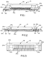
- the invention is embodied in an electrical connector, generally designated 10, for mounting to a printed circuit board 12 (Figs. 2 and 4) with the printed circuit board having a cutout 14 in an edge 16 thereof.
- the printed circuit board also has a pair of slots 18 (Fig. 4) at the ends of the base of cutout 14.
- a plurality of circuit pads 20 are provided on one surface 12a of printed circuit board 12, between slots 18.
- the printed circuit board has a pair of solderable connecting pads 22 outside opposite ends of cutout 14 as clearly seen in Figure 4.
- Electrical connector 10 includes an elongated dielectric housing, generally designated 24, having opposite ends 24a and being adapted for mounting in cutout 14 in the printed circuit board as seen in Figure 2.
- the housing includes a pair of outwardly projecting wings at opposite ends 24a of the housing, the wings projecting longitudinally outwardly of the housing ends.
- wings 24b at opposite ends 24a of the housing are juxtaposed over bottom surface 12a of printed circuit board 12.
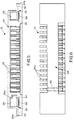
- Housing 24 of connector 10 mounts a plurality of terminals 26 (Figs. 5 and 6) which have solder tail portions 26a for solder connection to circuit pads 20 on surface 12a of the printed circuit board.
- the circuit pads on the printed circuit board are coupled to appropriate circuit traces (not shown) as is known in the art.
- a pair of retention members, generally designated 30, are mounted in end portions 24a of housing 24 for securing connector 10 to printed circuit board 12.
- the retention members include retention portions 32 which are engageable with pads 22 on surface 12a of printed circuit board 12.
- retention portions 32 of retention members 30 are sandwiched between wings 24b of the connector housing and surface 12a of the printed circuit board. The retention portions then can be solder connected to pads 22 on the printed circuit board for securing the connector to the board.
- Figures 7-9 show one of the retention members 30 which is stamped and formed of sheet metal material as a one-piece structure, including retention portions 32. As best seen in Figure 7, the retention portions 32 are bowed out of the plane of a generally planar body portion 34 of the retention member. This provides self-resiliency for the retention portion to effectively bias the retention portion against surface 12a and pad 22 of the printed circuit board.
- housing 24 of the connector includes a pair of generally rectangular receptacles 36 for receiving plug portions of a complementary mating connector or other connecting device.
- the left-hand receptacle 36 includes a polarizing or keying notch 36a.
- Retention members 30 have latch tongues 38 (see Figs. 7-9) which are located at the bottoms of receptacles 36.
- Each latch tongue has an aperture 40 (see Figs. 8 and 9) for receiving latch bosses on the latch plugs of the complementary mating connector or other connecting device.
- a pair of locating slots 18 are formed at opposite ends of the base of cutout 14.
- opposite ends 24a of connector housing 24 have stepped portions 24c which are adapted for positioning in locating slots 18 of the printed circuit board.
Landscapes
- Coupling Device And Connection With Printed Circuit (AREA)
- Details Of Connecting Devices For Male And Female Coupling (AREA)
- Multi-Conductor Connections (AREA)
Applications Claiming Priority (2)
| Application Number | Priority Date | Filing Date | Title |
|---|---|---|---|
| US791531 | 1997-01-30 | ||
| US08/791,531 US5855484A (en) | 1997-01-30 | 1997-01-30 | Board mounted electrical connector with improved retention means |
Publications (2)
| Publication Number | Publication Date |
|---|---|
| EP0856921A2 true EP0856921A2 (de) | 1998-08-05 |
| EP0856921A3 EP0856921A3 (de) | 2000-04-12 |
Family
ID=25154032
Family Applications (1)
| Application Number | Title | Priority Date | Filing Date |
|---|---|---|---|
| EP98101048A Withdrawn EP0856921A3 (de) | 1997-01-30 | 1998-01-22 | Elektrischer Leiterplatten - Steckverbinder mit Halteteilen |
Country Status (5)
| Country | Link |
|---|---|
| US (1) | US5855484A (de) |
| EP (1) | EP0856921A3 (de) |
| JP (1) | JP2967480B2 (de) |
| AU (1) | AU724160B2 (de) |
| NO (1) | NO316750B1 (de) |
Families Citing this family (7)
| Publication number | Priority date | Publication date | Assignee | Title |
|---|---|---|---|---|
| FR2762147B1 (fr) * | 1997-04-11 | 1999-09-10 | Framatome Connectors Int | Connecteur d'entree/sortie pour dispositif portable et procede de montage dudit connecteur |
| FR2762150A1 (fr) * | 1997-04-11 | 1998-10-16 | Framatome Connectors Int | Connecteur d'entree/sortie pour dispositif portable de communication et procede de montage dudit connecteur |
| US6878066B2 (en) * | 1998-02-13 | 2005-04-12 | Freedom Wave Llc | Wireless game control units |
| US6398577B1 (en) | 2000-10-04 | 2002-06-04 | Molex Incorporated | Latching/unlatching system for electrical connectors |
| US6383010B1 (en) | 2001-04-23 | 2002-05-07 | Molex Incorporated | Latching system for electrical connectors |
| US20060148314A1 (en) * | 2004-12-30 | 2006-07-06 | Motorola, Inc. | PCB mounted audio jack |
| CN201130741Y (zh) * | 2007-08-17 | 2008-10-08 | 富士康(昆山)电脑接插件有限公司 | 电连接器 |
Family Cites Families (10)
| Publication number | Priority date | Publication date | Assignee | Title |
|---|---|---|---|---|
| US5096436A (en) * | 1989-12-20 | 1992-03-17 | Burndy Corporation | Method of manufacturing a cable connector assembly |
| US5021002A (en) * | 1989-12-20 | 1991-06-04 | Burndy Corporation | Snap-lock electrical connector with quick release |
| US5234357A (en) * | 1990-07-04 | 1993-08-10 | Hirose Electric Co., Ltd. | Lock mechanism for electrical connector |
| JP3302689B2 (ja) * | 1991-07-16 | 2002-07-15 | バーグ・テクノロジー・インコーポレーテッド | コネクタハウジングのための保持システム |
| US5186654A (en) * | 1992-03-11 | 1993-02-16 | Molex Incorporated | Retention system for electrical connectors on printed circuit boards |
| JP2808975B2 (ja) * | 1992-04-01 | 1998-10-08 | 日本電気株式会社 | 電気部品 |
| US5269694A (en) * | 1992-10-23 | 1993-12-14 | Molex Incorporated | Surface mount electrical connector |
| US5319523A (en) * | 1993-10-20 | 1994-06-07 | Compaq Computer Corporation | Card edge interconnect apparatus for printed circuit boards |
| JP2845118B2 (ja) * | 1994-01-18 | 1999-01-13 | 松下電器産業株式会社 | コネクタの実装構造 |
| US5540598A (en) * | 1994-06-16 | 1996-07-30 | The Whitaker Corporation | Pin spacer for an electrical connector |
-
1997
- 1997-01-30 US US08/791,531 patent/US5855484A/en not_active Expired - Fee Related
-
1998
- 1998-01-22 EP EP98101048A patent/EP0856921A3/de not_active Withdrawn
- 1998-01-29 NO NO19980388A patent/NO316750B1/no not_active IP Right Cessation
- 1998-01-29 AU AU52811/98A patent/AU724160B2/en not_active Ceased
- 1998-01-30 JP JP10055664A patent/JP2967480B2/ja not_active Expired - Fee Related
Also Published As
| Publication number | Publication date |
|---|---|
| US5855484A (en) | 1999-01-05 |
| JPH10241805A (ja) | 1998-09-11 |
| NO980388D0 (no) | 1998-01-29 |
| AU724160B2 (en) | 2000-09-14 |
| EP0856921A3 (de) | 2000-04-12 |
| NO980388L (no) | 1998-07-31 |
| JP2967480B2 (ja) | 1999-10-25 |
| NO316750B1 (no) | 2004-04-26 |
| AU5281198A (en) | 1998-08-06 |
Similar Documents
| Publication | Publication Date | Title |
|---|---|---|
| US5104326A (en) | Printed circuit board shielded electrical connector | |
| US6475033B1 (en) | Electrical connector | |
| US7217159B2 (en) | Electrical connector with retaining device | |
| US6398587B1 (en) | Universal serial bus connector | |
| US5186654A (en) | Retention system for electrical connectors on printed circuit boards | |
| US5613860A (en) | Universal grounding clip for card-receiving connector | |
| EP0883215B1 (de) | Abgeschirmter elektrischer Verbinder | |
| US5755592A (en) | Combined ground strap and board lock for electrical connector assembly | |
| US5622519A (en) | Retention system for electrical connectors on printed circuit boards | |
| US6537084B2 (en) | Electrical connector with electrical shield having latch and mounting arms | |
| US6592408B2 (en) | Sink-type audio socket connector having improved grounding structure | |
| EP0856922B1 (de) | Leiterplattenverbinder mit Gabelmontage | |
| US6435905B1 (en) | Compact electrical connector having boardlocks | |
| WO2002082588A1 (en) | Retention system for electrical connectors | |
| US6589061B1 (en) | Printed circuit board for straddle mount electrical connector and method for pasting the same | |
| US6099353A (en) | IC card connector | |
| US20040082208A1 (en) | Electrical connector with rear ground plate | |
| US6345992B1 (en) | Electrical connector for mounting on a printed circuit board and including a terminal tail aligner | |
| US6022244A (en) | Electrical connector | |
| US6293825B1 (en) | Electrical connector | |
| US5855484A (en) | Board mounted electrical connector with improved retention means | |
| US6190183B1 (en) | Electrical connector | |
| US6629857B1 (en) | Electrical connector having improved shell | |
| US6685504B1 (en) | Shielded electrical connector assembly having reliable grounding capabilities | |
| US20030232517A1 (en) | Electrical connector assembly |
Legal Events
| Date | Code | Title | Description |
|---|---|---|---|
| PUAI | Public reference made under article 153(3) epc to a published international application that has entered the european phase |
Free format text: ORIGINAL CODE: 0009012 |
|
| AK | Designated contracting states |
Kind code of ref document: A2 Designated state(s): DE FR GB IT |
|
| AX | Request for extension of the european patent |
Free format text: AL;LT;LV;MK;RO;SI |
|
| PUAL | Search report despatched |
Free format text: ORIGINAL CODE: 0009013 |
|
| AK | Designated contracting states |
Kind code of ref document: A3 Designated state(s): AT BE CH DE DK ES FI FR GB GR IE IT LI LU MC NL PT SE |
|
| AX | Request for extension of the european patent |
Free format text: AL;LT;LV;MK;RO;SI |
|
| RIC1 | Information provided on ipc code assigned before grant |
Free format text: 7H 01R 23/68 A, 7H 01R 23/70 B |
|
| 17P | Request for examination filed |
Effective date: 20000929 |
|
| AKX | Designation fees paid |
Free format text: DE FR GB IT |
|
| 17Q | First examination report despatched |
Effective date: 20061222 |
|
| STAA | Information on the status of an ep patent application or granted ep patent |
Free format text: STATUS: THE APPLICATION IS DEEMED TO BE WITHDRAWN |
|
| 18D | Application deemed to be withdrawn |
Effective date: 20070703 |