EP0857131B1 - Système de freinage avec maitre-cylindre et pompe hydraulique - Google Patents
Système de freinage avec maitre-cylindre et pompe hydraulique Download PDFInfo
- Publication number
- EP0857131B1 EP0857131B1 EP96939014A EP96939014A EP0857131B1 EP 0857131 B1 EP0857131 B1 EP 0857131B1 EP 96939014 A EP96939014 A EP 96939014A EP 96939014 A EP96939014 A EP 96939014A EP 0857131 B1 EP0857131 B1 EP 0857131B1
- Authority
- EP
- European Patent Office
- Prior art keywords
- pressure
- hydraulic fluid
- cylinder
- hydraulic pump
- brake
- Prior art date
- Legal status (The legal status is an assumption and is not a legal conclusion. Google has not performed a legal analysis and makes no representation as to the accuracy of the status listed.)
- Expired - Lifetime
Links
- 239000012530 fluid Substances 0.000 abstract 3
Images
Classifications
-
- B—PERFORMING OPERATIONS; TRANSPORTING
- B60—VEHICLES IN GENERAL
- B60T—VEHICLE BRAKE CONTROL SYSTEMS OR PARTS THEREOF; BRAKE CONTROL SYSTEMS OR PARTS THEREOF, IN GENERAL; ARRANGEMENT OF BRAKING ELEMENTS ON VEHICLES IN GENERAL; PORTABLE DEVICES FOR PREVENTING UNWANTED MOVEMENT OF VEHICLES; VEHICLE MODIFICATIONS TO FACILITATE COOLING OF BRAKES
- B60T8/00—Arrangements for adjusting wheel-braking force to meet varying vehicular or ground-surface conditions, e.g. limiting or varying distribution of braking force
- B60T8/32—Arrangements for adjusting wheel-braking force to meet varying vehicular or ground-surface conditions, e.g. limiting or varying distribution of braking force responsive to a speed condition, e.g. acceleration or deceleration
- B60T8/321—Arrangements for adjusting wheel-braking force to meet varying vehicular or ground-surface conditions, e.g. limiting or varying distribution of braking force responsive to a speed condition, e.g. acceleration or deceleration deceleration
- B60T8/3255—Systems in which the braking action is dependent on brake pedal data
- B60T8/326—Hydraulic systems
- B60T8/3265—Hydraulic systems with control of the booster
-
- B—PERFORMING OPERATIONS; TRANSPORTING
- B60—VEHICLES IN GENERAL
- B60T—VEHICLE BRAKE CONTROL SYSTEMS OR PARTS THEREOF; BRAKE CONTROL SYSTEMS OR PARTS THEREOF, IN GENERAL; ARRANGEMENT OF BRAKING ELEMENTS ON VEHICLES IN GENERAL; PORTABLE DEVICES FOR PREVENTING UNWANTED MOVEMENT OF VEHICLES; VEHICLE MODIFICATIONS TO FACILITATE COOLING OF BRAKES
- B60T13/00—Transmitting braking action from initiating means to ultimate brake actuator with power assistance or drive; Brake systems incorporating such transmitting means, e.g. air-pressure brake systems
- B60T13/10—Transmitting braking action from initiating means to ultimate brake actuator with power assistance or drive; Brake systems incorporating such transmitting means, e.g. air-pressure brake systems with fluid assistance, drive, or release
- B60T13/66—Electrical control in fluid-pressure brake systems
- B60T13/68—Electrical control in fluid-pressure brake systems by electrically-controlled valves
- B60T13/686—Electrical control in fluid-pressure brake systems by electrically-controlled valves in hydraulic systems or parts thereof
-
- B—PERFORMING OPERATIONS; TRANSPORTING
- B60—VEHICLES IN GENERAL
- B60T—VEHICLE BRAKE CONTROL SYSTEMS OR PARTS THEREOF; BRAKE CONTROL SYSTEMS OR PARTS THEREOF, IN GENERAL; ARRANGEMENT OF BRAKING ELEMENTS ON VEHICLES IN GENERAL; PORTABLE DEVICES FOR PREVENTING UNWANTED MOVEMENT OF VEHICLES; VEHICLE MODIFICATIONS TO FACILITATE COOLING OF BRAKES
- B60T13/00—Transmitting braking action from initiating means to ultimate brake actuator with power assistance or drive; Brake systems incorporating such transmitting means, e.g. air-pressure brake systems
- B60T13/74—Transmitting braking action from initiating means to ultimate brake actuator with power assistance or drive; Brake systems incorporating such transmitting means, e.g. air-pressure brake systems with electrical assistance or drive
- B60T13/745—Transmitting braking action from initiating means to ultimate brake actuator with power assistance or drive; Brake systems incorporating such transmitting means, e.g. air-pressure brake systems with electrical assistance or drive acting on a hydraulic system, e.g. a master cylinder
-
- B—PERFORMING OPERATIONS; TRANSPORTING
- B60—VEHICLES IN GENERAL
- B60T—VEHICLE BRAKE CONTROL SYSTEMS OR PARTS THEREOF; BRAKE CONTROL SYSTEMS OR PARTS THEREOF, IN GENERAL; ARRANGEMENT OF BRAKING ELEMENTS ON VEHICLES IN GENERAL; PORTABLE DEVICES FOR PREVENTING UNWANTED MOVEMENT OF VEHICLES; VEHICLE MODIFICATIONS TO FACILITATE COOLING OF BRAKES
- B60T8/00—Arrangements for adjusting wheel-braking force to meet varying vehicular or ground-surface conditions, e.g. limiting or varying distribution of braking force
- B60T8/32—Arrangements for adjusting wheel-braking force to meet varying vehicular or ground-surface conditions, e.g. limiting or varying distribution of braking force responsive to a speed condition, e.g. acceleration or deceleration
- B60T8/34—Arrangements for adjusting wheel-braking force to meet varying vehicular or ground-surface conditions, e.g. limiting or varying distribution of braking force responsive to a speed condition, e.g. acceleration or deceleration having a fluid pressure regulator responsive to a speed condition
- B60T8/40—Arrangements for adjusting wheel-braking force to meet varying vehicular or ground-surface conditions, e.g. limiting or varying distribution of braking force responsive to a speed condition, e.g. acceleration or deceleration having a fluid pressure regulator responsive to a speed condition comprising an additional fluid circuit including fluid pressurising means for modifying the pressure of the braking fluid, e.g. including wheel driven pumps for detecting a speed condition, or pumps which are controlled by means independent of the braking system
- B60T8/4018—Pump units characterised by their drive mechanisms
-
- B—PERFORMING OPERATIONS; TRANSPORTING
- B60—VEHICLES IN GENERAL
- B60T—VEHICLE BRAKE CONTROL SYSTEMS OR PARTS THEREOF; BRAKE CONTROL SYSTEMS OR PARTS THEREOF, IN GENERAL; ARRANGEMENT OF BRAKING ELEMENTS ON VEHICLES IN GENERAL; PORTABLE DEVICES FOR PREVENTING UNWANTED MOVEMENT OF VEHICLES; VEHICLE MODIFICATIONS TO FACILITATE COOLING OF BRAKES
- B60T8/00—Arrangements for adjusting wheel-braking force to meet varying vehicular or ground-surface conditions, e.g. limiting or varying distribution of braking force
- B60T8/32—Arrangements for adjusting wheel-braking force to meet varying vehicular or ground-surface conditions, e.g. limiting or varying distribution of braking force responsive to a speed condition, e.g. acceleration or deceleration
- B60T8/34—Arrangements for adjusting wheel-braking force to meet varying vehicular or ground-surface conditions, e.g. limiting or varying distribution of braking force responsive to a speed condition, e.g. acceleration or deceleration having a fluid pressure regulator responsive to a speed condition
- B60T8/40—Arrangements for adjusting wheel-braking force to meet varying vehicular or ground-surface conditions, e.g. limiting or varying distribution of braking force responsive to a speed condition, e.g. acceleration or deceleration having a fluid pressure regulator responsive to a speed condition comprising an additional fluid circuit including fluid pressurising means for modifying the pressure of the braking fluid, e.g. including wheel driven pumps for detecting a speed condition, or pumps which are controlled by means independent of the braking system
- B60T8/404—Control of the pump unit
- B60T8/4063—Control of the pump unit involving the direction of fluid flow
-
- B—PERFORMING OPERATIONS; TRANSPORTING
- B60—VEHICLES IN GENERAL
- B60T—VEHICLE BRAKE CONTROL SYSTEMS OR PARTS THEREOF; BRAKE CONTROL SYSTEMS OR PARTS THEREOF, IN GENERAL; ARRANGEMENT OF BRAKING ELEMENTS ON VEHICLES IN GENERAL; PORTABLE DEVICES FOR PREVENTING UNWANTED MOVEMENT OF VEHICLES; VEHICLE MODIFICATIONS TO FACILITATE COOLING OF BRAKES
- B60T8/00—Arrangements for adjusting wheel-braking force to meet varying vehicular or ground-surface conditions, e.g. limiting or varying distribution of braking force
- B60T8/32—Arrangements for adjusting wheel-braking force to meet varying vehicular or ground-surface conditions, e.g. limiting or varying distribution of braking force responsive to a speed condition, e.g. acceleration or deceleration
- B60T8/34—Arrangements for adjusting wheel-braking force to meet varying vehicular or ground-surface conditions, e.g. limiting or varying distribution of braking force responsive to a speed condition, e.g. acceleration or deceleration having a fluid pressure regulator responsive to a speed condition
- B60T8/44—Arrangements for adjusting wheel-braking force to meet varying vehicular or ground-surface conditions, e.g. limiting or varying distribution of braking force responsive to a speed condition, e.g. acceleration or deceleration having a fluid pressure regulator responsive to a speed condition co-operating with a power-assist booster means associated with a master cylinder for controlling the release and reapplication of brake pressure through an interaction with the power assist device, i.e. open systems
- B60T8/441—Arrangements for adjusting wheel-braking force to meet varying vehicular or ground-surface conditions, e.g. limiting or varying distribution of braking force responsive to a speed condition, e.g. acceleration or deceleration having a fluid pressure regulator responsive to a speed condition co-operating with a power-assist booster means associated with a master cylinder for controlling the release and reapplication of brake pressure through an interaction with the power assist device, i.e. open systems using hydraulic boosters
-
- B—PERFORMING OPERATIONS; TRANSPORTING
- B60—VEHICLES IN GENERAL
- B60T—VEHICLE BRAKE CONTROL SYSTEMS OR PARTS THEREOF; BRAKE CONTROL SYSTEMS OR PARTS THEREOF, IN GENERAL; ARRANGEMENT OF BRAKING ELEMENTS ON VEHICLES IN GENERAL; PORTABLE DEVICES FOR PREVENTING UNWANTED MOVEMENT OF VEHICLES; VEHICLE MODIFICATIONS TO FACILITATE COOLING OF BRAKES
- B60T8/00—Arrangements for adjusting wheel-braking force to meet varying vehicular or ground-surface conditions, e.g. limiting or varying distribution of braking force
- B60T8/32—Arrangements for adjusting wheel-braking force to meet varying vehicular or ground-surface conditions, e.g. limiting or varying distribution of braking force responsive to a speed condition, e.g. acceleration or deceleration
- B60T8/34—Arrangements for adjusting wheel-braking force to meet varying vehicular or ground-surface conditions, e.g. limiting or varying distribution of braking force responsive to a speed condition, e.g. acceleration or deceleration having a fluid pressure regulator responsive to a speed condition
- B60T8/48—Arrangements for adjusting wheel-braking force to meet varying vehicular or ground-surface conditions, e.g. limiting or varying distribution of braking force responsive to a speed condition, e.g. acceleration or deceleration having a fluid pressure regulator responsive to a speed condition connecting the brake actuator to an alternative or additional source of fluid pressure, e.g. traction control systems
- B60T8/4809—Traction control, stability control, using both the wheel brakes and other automatic braking systems
- B60T8/4827—Traction control, stability control, using both the wheel brakes and other automatic braking systems in hydraulic brake systems
- B60T8/4845—Traction control, stability control, using both the wheel brakes and other automatic braking systems in hydraulic brake systems using a booster or a master cylinder for traction control
Definitions
- the present invention relates to a brake system with the features mentioned in the preamble of claim 1.
- Such a brake system is from Patent Abstracts of Japan vol. 010, no. 196 (M-497) and JP 61 04 1654 A. she should be independent of the brake pedal actuation by the driver Allow generation of braking force. This is for anti-slip rules, Driving dynamics controls, automatic distance control, required.
- the Brake pressure in the individual wheel brakes modulated by ABS systems which are arranged in the brake circuit (s).
- This controllable Pressure source can be activated by electrical energy.
- the invention has for its object a brake system to simplify the type mentioned at the beginning
- the object is achieved with a brake system, the features mentioned in the preamble of claim 1 and in which the hydraulic pump is set up to Pump hydraulic fluid in one direction only, and a controllable by the electrical control unit (ECU) Pressure relief valve between the outlet side and the inlet side the hydraulic pump is arranged, wherein in the pressure reduction phase in at least one Position of the hydraulic fluid pressure relief valve from the outlet side can flow to the hydraulic fluid reservoir.
- ECU electrical control unit
- the pressure source should be Pressure maintenance and pressure reduction position can be brought.
- the controllable Pressure source can be a hydraulic pump, its inlet side hydraulically connected to a hydraulic fluid reservoir and its outlet side with that in the master brake cylinder arranged pressure chamber is hydraulically connected, the volume change actuation of the master brake cylinder. This is especially true for hydraulic pumps with high Delivery rate and high pump dynamics.
- the hydraulic pump is set up to Promote hydraulic fluid in one direction, and a pressure relief valve controllable by the electrical control unit is between the outlet side and the inlet side of the Hydraulic pump arranged, being in at least one position of the pressure relief valve hydraulic fluid from the pressure outlet side to the hydraulic fluid reservoir or the inlet side can flow.
- a pressure relief valve controllable by the electrical control unit is between the outlet side and the inlet side of the Hydraulic pump arranged, being in at least one position of the pressure relief valve hydraulic fluid from the pressure outlet side to the hydraulic fluid reservoir or the inlet side can flow.
- THIS basically has the same effect like a hydraulic pump, the hydraulic fluid in two delivery directions can promote. However, the dynamic is Depressurization phase less.
- a pressure sensor arrangement is provided which fluid pressure acting on the pressure chamber of the master brake cylinder detected and one representative of the current fluid pressure electrical signal to the electronic control unit emits.
- a sensor arrangement provided that detects an operation of the brake pedal and a signal representative of this actuation to the electronic control unit.
- the electronic control unit can be dependent regardless of the operation of the brake pedal, but also regardless actuate the master brake cylinder. This can either support the one initiated by the driver Pedal actuation, or a targeted entry into the Driving behavior of the driver.
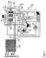
- FIG. 1 shows part of a brake system 10 for motor vehicles with a master brake cylinder 12 which is a cylinder / piston assembly 14, 16, which is operated by a brake pedal 18 can be actuated by two brake circuits 22, 24 hydraulic fluid supply.
- An ABS modulation device is in the brake circuit 22, 24 26 inserted to the four wheel brakes (VR, VL, HR, HL) controlled with hydraulic fluid.
- the cylinder 14 of the cylinder / piston assembly in the master brake cylinder 12 is designed as a double cylinder to the to control two brake circuits 22, 24 separately.
- the piston 16 is via an actuating rod 28 with the Brake pedal 18 coupled, which protrudes into the cylinder 14.
- the cylinder 14 is on its the brake pedal 18 facing End covered fluid-tight by a cover 30, so that between the piston 16 and the cover 30 a chamber 32 is formed.
- the chamber 32 is through a connection 34 and via a hydraulic line 36 with a connection 38 of a Electromagnetically controllable 3/2-way valve 40 connected.
- Another connection 42 of the valve 40 is via a hydraulic line 44 connected to a hydraulic fluid reservoir 46, this also includes the cylinder / piston arrangement 14, 16 of the master brake cylinder 12 feeds.
- a third connection 48 is via a Hydraulic line 50 an outlet side 52 with a hydraulic pump 54 connected.
- the hydraulic pump 54 is activated by a motor 56 which is controlled by an electronic control unit ECU.
- the electronic control unit ECU also controls the actuation of valve 40.
- An inlet side 58 of the hydraulic pump 54 is also connected to the hydraulic fluid reservoir 46.
- the hydraulic pump 54 thus acts as from the electronic one Control unit ECU controllable pressure source, the piston 16 of the cylinder / piston assembly 14, 16 with hydraulic fluid applied when hydraulic fluid from the outlet side 52 of the Hydraulic pump 54 through the hydraulic line 50, the valve 40, the hydraulic line 36 enters the pressure chamber 32, so that the piston 16 moves in the direction of arrow A when the hydraulic fluid increases the volume of the pressure chamber 32.
- the brake circuits 22, 24 with hydraulic fluid be fed from the master cylinder, so that the pressure on the wheel brakes VR, VL, HR and / or HL increases.
- a pressure accumulator is located on the outlet side 52 of the hydraulic pump 54 60 connected. This may not be sufficient Dynamic performance of the hydraulic pump 54 be balanced. To avoid the burst pressure of the system a pressure relief valve 62 is provided, that the pressure inlet side 58 with the outlet side 52 of the hydraulic pump 54 connects.
- the valve 40 can be brought into three positions.
- First (shown) position I is the pressure chamber 32 with the Hydraulic fluid reservoir 46 connected. This corresponds to one Pressure reduction phase.
- second position II are the pressure chamber 32, the hydraulic fluid reservoir 46 and the hydraulic pump 54 or the hydraulic accumulator 60 against each other shut off. This corresponds to a pressure maintenance phase.
- the third position is the outlet side 52 of the hydraulic pump 54 or the hydraulic accumulator 60 via the connection 48 of the valve 40 connected to the port 38 of the valve 40 so that Hydraulic fluid from the pressure accumulator 60 or the hydraulic pump 54 can flow into the pressure chamber 32. This matches with a pressure build-up phase.
- the valve 40 is in its (shown) unactuated position in the first position I as a Spring element 66 urges the valve member into this position.
- a pressure sensor 46 is arranged in the hydraulic line 36, the one for the pressure in the hydraulic line 36 or in the Pressure chamber 32 representatives electrical signal to the electronic control unit ECU conducts. Furthermore is a Travel sensor 68 coupled to the brake pedal 18 in order for a Actuation of the brake pedal representative signal to the electronic control unit ECU. Instead of the displacement sensor 68 any other sensor (rotation angle sensor, Force sensor, acceleration sensor etc.) is used become.
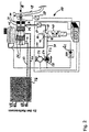
- the brake system illustrated in Fig. 2 differs from the brake system according to FIG. 1 only in that the accumulator 60 is omitted from FIG. 1, since a pump used with increased delivery capacity and increased pump dynamics is. This makes it possible to close the pressure accumulator 60 superfluous, especially since the beginning of the pressure build-up phase effective pressure accumulator through the increased delivery capacity of the Hydraulic pump 54 is replaced. Otherwise differ the braking systems according to FIGS. 1 and 2 are not.
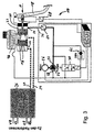
- Fig. 3 shows the simplified compared to Figs. 1 and 2 Embodiment of the invention as the 3/2-way solenoid valve 40 between the outlet side 52 of the hydraulic pump 54 and the Pressure chamber 32 is omitted.
- the Hydraulic pump 54 is set up in the pressure chamber 32 maintain pressure level.
- it is necessary to provide a pressure relief valve 70 that defines the outlet side 52 hydraulic pump 54 either connects to inlet side 58 (Position II in Fig. 3) or the pressure inlet side 58 of the pressure outlet side 53 separates (position I shown in Fig. 3). Otherwise, the brake systems differ according to 1, 2 not of the embodiment of FIG. 3rd
Landscapes
- Engineering & Computer Science (AREA)
- Physics & Mathematics (AREA)
- Fluid Mechanics (AREA)
- Transportation (AREA)
- Mechanical Engineering (AREA)
- Regulating Braking Force (AREA)
- Braking Systems And Boosters (AREA)
Abstract
Claims (4)
- Installation de freinage (10) comportant un cylindre principal de frein (12) qui présente au moins un ensemble piston-cylindre (14, 16) qui peut être actionnée par une pédale de frein (18) pour envoyer du fluide hydraulique à au moins un circuit de freinage (22, 24), cette installation comportant également:caractérisée en ce queune source de pression commandable, qui, est commandée par une unité de commande électronique ECU et qui alimente en fluide hydraulique le piston (16) de l'ensemble piston-cylindre (14, 16) en vue de l'envoi de fluide hydraulique au circuit de freinage (22, 24),la source de pression commandable étant une pompe hydraulique (54), dont le côté d'aspiration est relié hydrauliquement à un réservoir de fluide hydraulique, et dont le côté de refoulement (52) est relié hydrauliquement à un réservoir sous pression (60) et à une chambre de pression (32), qui est disposée dans le cylindre principal de frein (12) et dont la modification de volume provoque l'actionnement du cylindre principal de frein (12),la pompe hydraulique étant prévue pour ne délivrer du fluide hydraulique que dans une seule direction,une soupape de décharge de la pression (70), commandable par l'unité de commande électrique (ECU), est disposée entre le côté de refoulement (52) et le côté d'aspiration (58) de la pompe hydraulique (54), tandis que dans la phase d'abaissement de la pression, dans au moins une position de la soupape de décharge de la pression (70), du fluide hydraulique peut s'écouler du côté de refoulement (52) vers le réservoir de fluide hydraulique (46).
- Installation de freinage suivant la revendication 1, caractérisée en ce quele côté d'aspiration (58) de la pompe hydraulique (54) est reliée hydrauliquement au côté de refoulement (52) de la pompe hydraulique (54) par une soupape de limitation de la pression (62).
- Installation de freinage suivant l'une des revendications précédentes, caractérisée en ce queun dispositif de détecteur de la pression (64) est prévu, qui mesure la pression du fluide agissant sur la chambre de pression (32) du cylindre principal de frein (12) et émet, vers l'unité électronique de commande (ECU), un signal électrique représentatif de la pression instantanée du fluide.
- Installation de freinage suivant l'une des revendications précédentes, caractérisée en ce queun dispositif de détecteur (68) est prévu, qui détecte un actionnement de la pédale de frein (18) et émet, vers l'unité électronique de commande (ECU), un signal représentatif de cet actionnement.
Applications Claiming Priority (3)
| Application Number | Priority Date | Filing Date | Title |
|---|---|---|---|
| DE19542656 | 1995-11-15 | ||
| DE19542656A DE19542656A1 (de) | 1995-11-15 | 1995-11-15 | Bremsanlage |
| PCT/EP1996/004950 WO1997018116A1 (fr) | 1995-11-15 | 1996-11-12 | Systeme de freinage |
Publications (2)
| Publication Number | Publication Date |
|---|---|
| EP0857131A1 EP0857131A1 (fr) | 1998-08-12 |
| EP0857131B1 true EP0857131B1 (fr) | 2002-09-04 |
Family
ID=7777577
Family Applications (1)
| Application Number | Title | Priority Date | Filing Date |
|---|---|---|---|
| EP96939014A Expired - Lifetime EP0857131B1 (fr) | 1995-11-15 | 1996-11-12 | Système de freinage avec maitre-cylindre et pompe hydraulique |
Country Status (4)
| Country | Link |
|---|---|
| US (1) | US6290307B1 (fr) |
| EP (1) | EP0857131B1 (fr) |
| DE (2) | DE19542656A1 (fr) |
| WO (1) | WO1997018116A1 (fr) |
Cited By (2)
| Publication number | Priority date | Publication date | Assignee | Title |
|---|---|---|---|---|
| DE10338046B4 (de) * | 2003-08-19 | 2016-03-24 | Volkswagen Ag | Kraftfahrzeug-Bremssystem mit einem aktiven Bremskraftverstärker und integrierter ESP-und/oder EDS-und/oder ASR-Funktionalität |
| DE102006027039B4 (de) | 2006-06-08 | 2023-01-19 | Volkswagen Ag | Elektromechanischer Bremskraftverstärker |
Families Citing this family (19)
| Publication number | Priority date | Publication date | Assignee | Title |
|---|---|---|---|---|
| DE19731962C2 (de) | 1997-07-24 | 2000-08-03 | Lucas Ind Plc | Vollhydraulische Bremskraftverstärker/Hauptzylinder-Einheit |
| JP4333000B2 (ja) * | 1999-12-10 | 2009-09-16 | トヨタ自動車株式会社 | 車両用ブレーキシステム |
| DE10030031B4 (de) * | 2000-03-10 | 2012-05-31 | Continental Teves Ag & Co. Ohg | Elektrohydraulische Bremsanlage |
| JP4568948B2 (ja) * | 2000-03-30 | 2010-10-27 | 株式会社アドヴィックス | 車両の液圧ブレーキ装置 |
| DE10235932A1 (de) * | 2002-08-06 | 2004-02-19 | Continental Teves Ag & Co. Ohg | Geregeltes hydraulisches Bremssystem mit Druckmittel-Verbindung von der Pumpe zum Hauptzylinder |
| US6908128B2 (en) * | 2003-02-18 | 2005-06-21 | Russell W. Strong | External protection system for a vehicle |
| DE10318850A1 (de) * | 2003-04-25 | 2004-11-18 | Lucas Automotive Gmbh | Bremsanlage für ein Kraftfahrzeug |
| FR2855137B1 (fr) * | 2003-05-22 | 2006-06-09 | Bosch Gmbh Robert | Installation de freinage equipee d'un simulateur, pour vehicule et simulateur pour une telle installation |
| KR100954555B1 (ko) * | 2004-11-23 | 2010-04-23 | 주식회사 만도 | 피에조 액추에이터 장착 전자제어식 브레이크 시스템 |
| DE102005033258B3 (de) | 2005-07-15 | 2006-08-31 | Lucas Automotive Gmbh | Bremsanlage für ein Kraftfahrzeug |
| DE102006020303A1 (de) * | 2006-05-03 | 2007-11-08 | Volkswagen Ag | Betätigungseinrichtung für eine Fahrzeugbremsanlage |
| US20090096281A1 (en) * | 2007-10-15 | 2009-04-16 | International Truck Intellectual Property Company, Llc | Locking a vehicle's wheels using the vehicle's hydraulic-actuated service brakes |
| DE102009005937A1 (de) | 2009-01-23 | 2010-07-29 | Continental Teves Ag & Co. Ohg | Elektrohydraulisches Bremssystem sowie Verfahren zu dessen Betrieb |
| DE102010041642A1 (de) | 2010-09-29 | 2012-03-29 | Robert Bosch Gmbh | Bremssystem für ein Fahrzeug |
| DE102011077169A1 (de) * | 2011-06-08 | 2012-12-13 | Continental Teves Ag & Co. Ohg | Bremsanlage für Kraftfahrzeuge sowie Verfahren zum Betrieb einer Bremsanlage |
| US9120474B2 (en) | 2011-06-15 | 2015-09-01 | Arvinmeritor Technology, Llc | Mechanical bypass valve for regenerative air brake module |
| US8465107B2 (en) | 2011-06-15 | 2013-06-18 | Arvinmeritor Technology, Llc | Regenerative air brake module |
| DE102014200071A1 (de) * | 2013-03-05 | 2014-09-11 | Continental Teves Ag & Co. Ohg | Bremsanlage für ein Kraftfahrzeug |
| DE102023118341A1 (de) | 2023-07-11 | 2025-01-16 | Kramer-Werke Gmbh | Mobile Arbeitsmaschine mit einer Bremseinheit |
Citations (2)
| Publication number | Priority date | Publication date | Assignee | Title |
|---|---|---|---|---|
| US4625625A (en) * | 1983-04-30 | 1986-12-02 | Lucas Industries Public Limited Company | Vehicle hydraulic systems |
| US5249853A (en) * | 1991-04-19 | 1993-10-05 | Alfred Teves Gmbh | Hydraulic anti-lock brake system |
Family Cites Families (11)
| Publication number | Priority date | Publication date | Assignee | Title |
|---|---|---|---|---|
| DE3323402A1 (de) * | 1983-04-07 | 1984-10-18 | Alfred Teves Gmbh, 6000 Frankfurt | Bremsanlage fuer kraftfahrzeuge |
| JPS6141654A (ja) | 1984-08-02 | 1986-02-28 | Nippon Denso Co Ltd | 車両用推進制御装置 |
| DE3431823A1 (de) | 1984-08-30 | 1986-03-13 | Alfred Teves Gmbh, 6000 Frankfurt | Servoeinrichtung, insbesondere fuer eine kraftfahrzeug-bremsanlage |
| US4986612A (en) * | 1987-10-26 | 1991-01-22 | Nippon A B S, Ltd. | Brake fluid pressure control apparatus for a vehicle |
| DE3928109A1 (de) * | 1989-08-25 | 1991-02-28 | Bosch Gmbh Robert | Elektromotorisch antreibbarer druckerzeuger fuer eine hydraulische fahrzeug-bremsanlage |
| US5295739A (en) * | 1990-05-25 | 1994-03-22 | Alfred Teves Gmbh | Brake pressure control apparatus |
| JPH04283156A (ja) * | 1991-03-11 | 1992-10-08 | Nabco Ltd | 脈圧緩衝装置 |
| FR2703314B1 (fr) | 1993-04-02 | 1995-05-05 | Renault | Dispositif de freinage et pompe piézoélectrique de commande. |
| DE4314448A1 (de) * | 1993-05-03 | 1994-11-10 | Teves Gmbh Alfred | Bremsanlage für Kraftfahrzeuge mit elektrischem Antrieb |
| US5713640A (en) | 1994-01-20 | 1998-02-03 | Itt Automotive Europe Gmbh | Hydraulic braking system with an auxiliary pressure source having a quick fill chamber |
| DE19619985A1 (de) * | 1995-11-25 | 1997-05-28 | Bosch Gmbh Robert | Hydraulische Fahrzeugbremsanlage |
-
1995
- 1995-11-15 DE DE19542656A patent/DE19542656A1/de not_active Withdrawn
-
1996
- 1996-11-12 WO PCT/EP1996/004950 patent/WO1997018116A1/fr not_active Ceased
- 1996-11-12 US US09/068,682 patent/US6290307B1/en not_active Expired - Fee Related
- 1996-11-12 EP EP96939014A patent/EP0857131B1/fr not_active Expired - Lifetime
- 1996-11-12 DE DE59609629T patent/DE59609629D1/de not_active Expired - Fee Related
Patent Citations (2)
| Publication number | Priority date | Publication date | Assignee | Title |
|---|---|---|---|---|
| US4625625A (en) * | 1983-04-30 | 1986-12-02 | Lucas Industries Public Limited Company | Vehicle hydraulic systems |
| US5249853A (en) * | 1991-04-19 | 1993-10-05 | Alfred Teves Gmbh | Hydraulic anti-lock brake system |
Cited By (2)
| Publication number | Priority date | Publication date | Assignee | Title |
|---|---|---|---|---|
| DE10338046B4 (de) * | 2003-08-19 | 2016-03-24 | Volkswagen Ag | Kraftfahrzeug-Bremssystem mit einem aktiven Bremskraftverstärker und integrierter ESP-und/oder EDS-und/oder ASR-Funktionalität |
| DE102006027039B4 (de) | 2006-06-08 | 2023-01-19 | Volkswagen Ag | Elektromechanischer Bremskraftverstärker |
Also Published As
| Publication number | Publication date |
|---|---|
| EP0857131A1 (fr) | 1998-08-12 |
| US6290307B1 (en) | 2001-09-18 |
| WO1997018116A1 (fr) | 1997-05-22 |
| DE19542656A1 (de) | 1997-05-22 |
| DE59609629D1 (de) | 2002-10-10 |
Similar Documents
| Publication | Publication Date | Title |
|---|---|---|
| EP0857131B1 (fr) | Système de freinage avec maitre-cylindre et pompe hydraulique | |
| EP0807039B1 (fr) | Procede pour faire fonctionner un systeme de freinage de vehicules a moteur a antiderapeur automatique | |
| DE202018006953U1 (de) | Zwei-Box-Bremssystem | |
| DE102018002990A1 (de) | Hydraulische Kraftfahrzeug-Bremsanlage und Verfahren zum Betreiben derselben | |
| DE19604134A1 (de) | Verfahren und Vorrichtung zur Steuerung der Bremsanlage von Kraftfahrzeugen mit elektrischem Antrieb | |
| DE10147150C1 (de) | Hydraulische Fremdkraftbremsanlage | |
| EP0854808A1 (fr) | Systeme d'actionnement de freins a regulation electronique | |
| WO1994025322A1 (fr) | Systeme de freinage pour automobiles a propulsion electrique | |
| EP0867349B1 (fr) | Système de commande de freinage pour véhicules automobiles muni d'une unité électronique de commande de vitesse commutable | |
| EP1175322B1 (fr) | Dispositif de freinage pour vehicules | |
| DE19500544A1 (de) | Elektronisch regelbares Bremsbetätigungssystem | |
| EP0459117B1 (fr) | Système de freinage hydraulique à double circuit | |
| DE68923798T2 (de) | Anpassungsfähiges bremssystem mit einem hydraulischen verstärker und einem rückförderungssystem. | |
| DE10319194B3 (de) | Kombinierte hydraulische und elektromechanische Fahrzeugbremsanlage mit einer Bremskraftregeleinrichtung | |
| DE10053993B4 (de) | Hydraulische Bremsanlage und Verfahren zur Bremsdruckerzeugung und -regelung für Fahrzeugbremssystem | |
| EP0907534A1 (fr) | Systeme de freinage hydraulique | |
| EP0867325B1 (fr) | Système de contrôle de freinage avec dispositif de commande de la vitesse pouvant être mis en circuit ou hors circuit | |
| DE4333568A1 (de) | Bremsanlage für Kraftfahrzeuge mit einer Einrichtung zum Regeln sowohl des Brems- als auch des Antriebsschlupfes | |
| WO1999039954A1 (fr) | Systeme d'actionnement de frein regulable electroniquement pour vehicules automobiles et procede pour la commande d'un tel systeme d'actionnement | |
| DE4027793A1 (de) | Anordnung zum halten eines fahrzeugs auf einer geneigten fahrbahn | |
| DE102005061543B4 (de) | Hydraulische Zweikreis-Fahrzeugbremsanlage | |
| DE19843221B4 (de) | Fahrdynamikregelsystem und Verfahren zum Betreiben eines solchen Fahrdynamikregelsystems | |
| DE10065234A1 (de) | Elektrohydraulische Fahrzeugbremsanlage | |
| DE3623149A1 (de) | Bremsanlage fuer kraftfahrzeuge mit bremsschlupf- und antriebsschlupfregelung | |
| WO2021063577A1 (fr) | Procédé de commande d'un système de freinage assisté externe à régulation électronique de patinage, en particulier pour un véhicule automobile, et système de freinage assisté externe à régulation électronique de patinage, en particulier pour un véhicule automobile |
Legal Events
| Date | Code | Title | Description |
|---|---|---|---|
| PUAI | Public reference made under article 153(3) epc to a published international application that has entered the european phase |
Free format text: ORIGINAL CODE: 0009012 |
|
| 17P | Request for examination filed |
Effective date: 19980514 |
|
| AK | Designated contracting states |
Kind code of ref document: A1 Designated state(s): DE FR GB |
|
| RAP1 | Party data changed (applicant data changed or rights of an application transferred) |
Owner name: LUCAS INDUSTRIES LIMITED |
|
| 17Q | First examination report despatched |
Effective date: 20000814 |
|
| GRAG | Despatch of communication of intention to grant |
Free format text: ORIGINAL CODE: EPIDOS AGRA |
|
| RTI1 | Title (correction) |
Free format text: BRAKE SYSTEM WITH MASTER-CYLINDER AND HYDRAULIC PUMP |
|
| GRAG | Despatch of communication of intention to grant |
Free format text: ORIGINAL CODE: EPIDOS AGRA |
|
| GRAG | Despatch of communication of intention to grant |
Free format text: ORIGINAL CODE: EPIDOS AGRA |
|
| GRAH | Despatch of communication of intention to grant a patent |
Free format text: ORIGINAL CODE: EPIDOS IGRA |
|
| RAP1 | Party data changed (applicant data changed or rights of an application transferred) |
Owner name: LUCAS INDUSTRIES LIMITED |
|
| GRAH | Despatch of communication of intention to grant a patent |
Free format text: ORIGINAL CODE: EPIDOS IGRA |
|
| GRAA | (expected) grant |
Free format text: ORIGINAL CODE: 0009210 |
|
| AK | Designated contracting states |
Kind code of ref document: B1 Designated state(s): DE FR GB |
|
| REG | Reference to a national code |
Ref country code: GB Ref legal event code: FG4D Free format text: NOT ENGLISH |
|
| GBT | Gb: translation of ep patent filed (gb section 77(6)(a)/1977) |
Effective date: 20020904 |
|
| REF | Corresponds to: |
Ref document number: 59609629 Country of ref document: DE Date of ref document: 20021010 |
|
| ET | Fr: translation filed | ||
| REG | Reference to a national code |
Ref country code: GB Ref legal event code: 732E |
|
| PLBE | No opposition filed within time limit |
Free format text: ORIGINAL CODE: 0009261 |
|
| STAA | Information on the status of an ep patent application or granted ep patent |
Free format text: STATUS: NO OPPOSITION FILED WITHIN TIME LIMIT |
|
| 26N | No opposition filed |
Effective date: 20030605 |
|
| REG | Reference to a national code |
Ref country code: GB Ref legal event code: 732E |
|
| PGFP | Annual fee paid to national office [announced via postgrant information from national office to epo] |
Ref country code: GB Payment date: 20061004 Year of fee payment: 11 |
|
| PGFP | Annual fee paid to national office [announced via postgrant information from national office to epo] |
Ref country code: FR Payment date: 20061103 Year of fee payment: 11 |
|
| REG | Reference to a national code |
Ref country code: GB Ref legal event code: 732E |
|
| GBPC | Gb: european patent ceased through non-payment of renewal fee |
Effective date: 20071112 |
|
| REG | Reference to a national code |
Ref country code: FR Ref legal event code: ST Effective date: 20080930 |
|
| PG25 | Lapsed in a contracting state [announced via postgrant information from national office to epo] |
Ref country code: GB Free format text: LAPSE BECAUSE OF NON-PAYMENT OF DUE FEES Effective date: 20071112 |
|
| PG25 | Lapsed in a contracting state [announced via postgrant information from national office to epo] |
Ref country code: FR Free format text: LAPSE BECAUSE OF NON-PAYMENT OF DUE FEES Effective date: 20071130 |
|
| PGFP | Annual fee paid to national office [announced via postgrant information from national office to epo] |
Ref country code: DE Payment date: 20081128 Year of fee payment: 13 |
|
| PG25 | Lapsed in a contracting state [announced via postgrant information from national office to epo] |
Ref country code: DE Free format text: LAPSE BECAUSE OF NON-PAYMENT OF DUE FEES Effective date: 20100601 |