EP0857268B1 - Schaltvorrichtung für kraftfahrzeug-wechselgetriebe - pneumatischer schaltservo - - Google Patents
Schaltvorrichtung für kraftfahrzeug-wechselgetriebe - pneumatischer schaltservo - Download PDFInfo
- Publication number
- EP0857268B1 EP0857268B1 EP96934744A EP96934744A EP0857268B1 EP 0857268 B1 EP0857268 B1 EP 0857268B1 EP 96934744 A EP96934744 A EP 96934744A EP 96934744 A EP96934744 A EP 96934744A EP 0857268 B1 EP0857268 B1 EP 0857268B1
- Authority
- EP
- European Patent Office
- Prior art keywords
- shift
- gear
- piston
- force
- lever
- Prior art date
- Legal status (The legal status is an assumption and is not a legal conclusion. Google has not performed a legal analysis and makes no representation as to the accuracy of the status listed.)
- Expired - Lifetime
Links
- 230000002787 reinforcement Effects 0.000 claims description 6
- 230000005540 biological transmission Effects 0.000 description 31
- 230000033001 locomotion Effects 0.000 description 11
- 210000001331 nose Anatomy 0.000 description 7
- 238000013461 design Methods 0.000 description 6
- 238000000034 method Methods 0.000 description 6
- 230000008569 process Effects 0.000 description 6
- 230000008859 change Effects 0.000 description 4
- 230000001360 synchronised effect Effects 0.000 description 4
- 230000000694 effects Effects 0.000 description 3
- 238000009434 installation Methods 0.000 description 3
- 238000009423 ventilation Methods 0.000 description 3
- 238000006243 chemical reaction Methods 0.000 description 2
- 210000003746 feather Anatomy 0.000 description 2
- 230000007935 neutral effect Effects 0.000 description 2
- 238000009420 retrofitting Methods 0.000 description 2
- 238000007789 sealing Methods 0.000 description 2
- 238000010276 construction Methods 0.000 description 1
- 230000007797 corrosion Effects 0.000 description 1
- 238000005260 corrosion Methods 0.000 description 1
- 230000001419 dependent effect Effects 0.000 description 1
- 238000002347 injection Methods 0.000 description 1
- 239000007924 injection Substances 0.000 description 1
- 238000003780 insertion Methods 0.000 description 1
- 230000037431 insertion Effects 0.000 description 1
- 239000002991 molded plastic Substances 0.000 description 1
- 230000003319 supportive effect Effects 0.000 description 1
- 230000007704 transition Effects 0.000 description 1
- 238000013519 translation Methods 0.000 description 1
- 238000013022 venting Methods 0.000 description 1
Images


Classifications
-
- F—MECHANICAL ENGINEERING; LIGHTING; HEATING; WEAPONS; BLASTING
- F16—ENGINEERING ELEMENTS AND UNITS; GENERAL MEASURES FOR PRODUCING AND MAINTAINING EFFECTIVE FUNCTIONING OF MACHINES OR INSTALLATIONS; THERMAL INSULATION IN GENERAL
- F16H—GEARING
- F16H61/00—Control functions within control units of change-speed- or reversing-gearings for conveying rotary motion ; Control of exclusively fluid gearing, friction gearing, gearings with endless flexible members or other particular types of gearing
- F16H61/26—Generation or transmission of movements for final actuating mechanisms
- F16H61/28—Generation or transmission of movements for final actuating mechanisms with at least one movement of the final actuating mechanism being caused by a non-mechanical force, e.g. power-assisted
- F16H61/30—Hydraulic or pneumatic motors or related fluid control means therefor
-
- F—MECHANICAL ENGINEERING; LIGHTING; HEATING; WEAPONS; BLASTING
- F16—ENGINEERING ELEMENTS AND UNITS; GENERAL MEASURES FOR PRODUCING AND MAINTAINING EFFECTIVE FUNCTIONING OF MACHINES OR INSTALLATIONS; THERMAL INSULATION IN GENERAL
- F16H—GEARING
- F16H61/00—Control functions within control units of change-speed- or reversing-gearings for conveying rotary motion ; Control of exclusively fluid gearing, friction gearing, gearings with endless flexible members or other particular types of gearing
- F16H61/26—Generation or transmission of movements for final actuating mechanisms
- F16H61/28—Generation or transmission of movements for final actuating mechanisms with at least one movement of the final actuating mechanism being caused by a non-mechanical force, e.g. power-assisted
- F16H61/30—Hydraulic or pneumatic motors or related fluid control means therefor
- F16H2061/301—Hydraulic or pneumatic motors or related fluid control means therefor for power assistance, i.e. servos with follow up action
-
- F—MECHANICAL ENGINEERING; LIGHTING; HEATING; WEAPONS; BLASTING
- F16—ENGINEERING ELEMENTS AND UNITS; GENERAL MEASURES FOR PRODUCING AND MAINTAINING EFFECTIVE FUNCTIONING OF MACHINES OR INSTALLATIONS; THERMAL INSULATION IN GENERAL
- F16H—GEARING
- F16H61/00—Control functions within control units of change-speed- or reversing-gearings for conveying rotary motion ; Control of exclusively fluid gearing, friction gearing, gearings with endless flexible members or other particular types of gearing
- F16H61/26—Generation or transmission of movements for final actuating mechanisms
- F16H61/28—Generation or transmission of movements for final actuating mechanisms with at least one movement of the final actuating mechanism being caused by a non-mechanical force, e.g. power-assisted
- F16H61/30—Hydraulic or pneumatic motors or related fluid control means therefor
- F16H2061/301—Hydraulic or pneumatic motors or related fluid control means therefor for power assistance, i.e. servos with follow up action
- F16H2061/302—Hydraulic or pneumatic motors or related fluid control means therefor for power assistance, i.e. servos with follow up action with variable force amplification, e.g. force is depending on selected gear or on actuator force (non-linear amplification)
Definitions
- the invention relates to a switching device for Motor vehicle change transmission according to the preamble of the claim 1.
- the rotary movement is used the shift rod for preselecting the individual shift gates and generally does not require high shifting forces.
- the axial longitudinal movement of the shift rod is used for insertion of the desired gear and requires in particular Transmissions for heavy vehicles and such vehicles, whose driver's seat is located away from the transmission, larger Switching forces.
- Pneumatic switching aids of this type are known in a resolved design, which consist of a mechanical-pneumatic control part and a separate, pneumatic force part.
- a switching aid in a disassembled design is made of Loomann; Gear transmission; 2nd Edition; Springer Verlag; 1988; P. 225 known.
- the control section is a mechanically operated control valve that is actuated by the shift linkage. The transmission of the selection movement when changing gears is done mechanically directly to the transmission. When the switching movement is transmitted, the control valve is actuated and at the same time the manual shifting force is transmitted mechanically to the transmission via a lever.
- the manual switching force is additionally pneumatically supported by a compressed air cylinder.
- This compressed air cylinder as a two-position cylinder with an integrated hydraulic damper, forms the pneumatic power unit.
- the arrangement has the disadvantage that the forces in the compressed air cylinder are the same on both sides of the piston. An increased shifting force adapted to the gear stages to be shifted is therefore not achievable.
- the invention has for its object the switching device so that the pneumatically reinforced Shifting forces for the one gear stage to be shifted are larger than for the other gear.
- the one responsible for switching in a first direction an actuating piston and the correspondingly assigned Side of the piston is in the switching device according to the invention designed differently than that for the circuit in the second, opposite direction actuating piston and the opposite side of the piston.
- a pressure medium supporting the driver it is preferred Air used.
- the larger Switching force should be designed to be larger than the loaded surfaces on the side of the piston, the should generate the lower switching force.
- the size of the approved Force can depend on the permissible Strain on the connected circuit components be made.
- control valve and the power part combined in one component.
- the driver's shifting force is dependent on the shifting force or depending on the geometric arrangement of the valve characteristic or piston surface, reinforced and acts accordingly a manual transmission.
- the driver doesn't lose the feeling for the gearshift, his sense of whether a gear is inserted or how long the synchronization phase lasts, he can feel it immediately.
- the switching movement of a gear shift device supported by compressed air as an assistant be during the dialing motion by hand running without support.
- the driver can still shift manually when the Air pressure due to damage in the compressed air system should be small or should turn out completely. To do this no switching measures of any kind are required.
- the braking ability of the motor vehicle, provided that the transmission is provided remains secured.
- the compressed air support controls a large part the force to be applied when shifting - but only so much that the driver maintains the shift feeling.
- the manual force to be applied manually by the driver is indicated by a pneumatic switching aid to a fraction of the total required force is reduced.
- Synchronized Commercial vehicle transmissions are also used in heavy vehicles to light shift transmissions. When driving downhill will downshift the transmission, especially in the lower gears, extremely relieved and thereby will make a significant contribution to increasing accident safety contributed.
- the switching device finds its Area of application for all synchronized gearboxes with H shift, Double H circuit and superimposed H circuit. she finds also for mounting on the gearbox by the vehicle manufacturer very limited installation space sufficient space. At a The necessary downtime or retrofitting is downtime pleasantly short for the vehicle operator, because the entire switching device is replaced or can be installed without special settings Place on the vehicle.
- the shift path the transmission can be arranged by the arrangement of the invention Represent switching device also shortened. By appropriate interpretation of the lever ratios in the shift linkage the shift path for a standard gearbox to reduce. The shortened shift travel affects the shift lever positive for the driver.
- the driver also has during the switching process a constantly noticeable feedback to the shift sequence in the transmission.
- About the existing mechanical connection between the gear lever and the synchronization in the transmission the driver like a mechanical and unsupported Switching device the reactions of the transmission. Consequently there remains the possibility of intervention in the switching sequence received at any time and he can always expire Cancel switching process.
- the driver has a failure the compressed air support the switchability without restriction of the gearbox so that it can be used in emergencies Vehicle, probably with increased effort, but safe, can slow down by changing the translation.
- the auxiliary forces generated by it can be adapted to support the circuit to the switchgear between driver and transmission.
- the look-up effects often to be felt in pneumatic switching devices during the transition from the unlocking process to the free flight phase are eliminated or are compensated for by the switching device.
- rapid ventilation ensures that when the switching process is interrupted, there is no longer any pressure in the switching device which could undesirably accelerate the entire switching system up to the shift lever and cause this lookup effect.
- the switching device is completely depressurized when the switching sequence is interrupted.
- the switchgear 2 in a sketch of a motor vehicle. From a shift lever 4 leads a shift rod 6 via a lever deflection 8 to one Switching device 10.
- the switching device 10 has one Connection line 12 to a reservoir 14th leads from which the switching device 10 is supplied with compressed air becomes.
- the lever deflection 8 has a first one Lever 16, which is preferably articulated with the shift rod 6 connected is.
- the lever deflection 8 has one second lever 18, which in turn in a control rod 20th engages, which is arranged in the switching device 10. Furthermore, there is a piston rod in the switching device 10 22 provided, in which a lever 24 engages, which via a rotary shaft 26 with a lever 28 in the vehicle transmission 30 is connected.
- the lever 28 engages in one Shift rail 32, through the gear ratios in a known manner of the transmission can be switched.
- a movement of the lever 24 is in via the rotary shaft 26 in transmit a movement of the lever 28 so that the lever 28th set the shift rail 32 in an axial movement can.
- the shift rail 32 preferably takes three positions one, two axial end positions, that each correspond to a switched gear ratio and a middle position between the end positions, which corresponds to a neutral position of the transmission.
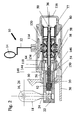
- Fig. 2 shows a sectional view of the invention Switching device 10.
- the switching device 10 can, as shown here, inserted in part of the transmission 30 be, or it is arranged separately on the outside of the housing.
- the Lever 18 is on the rotary shaft 16 with the one not shown here Shift linkage connected. About this shift linkage the lever 18 is moved by the driver.
- the rotary shaft 26 is provided, via which the lever 24 with others not shown here Components of the transmission interacts.
- the lever 18 engages in the control rod 20, which is located within a piston rod 22.
- the control rod 20 has an axial bore 36, from which radial Open openings 38, 40, 42, 46, 48.
- the control rod 20 has a preferably circular cross section.
- the Openings can, at the respective axial position, too unlike shown here offset by 180 ° on the Scope of the control rod 20 to be distributed. It is on the respective axial position also more than two openings possible.
- the axial opening 36 ends at one end in the control rod 20 and is on its opposite End closed by a screw 50.
- Within the piston rod 22 is a slide bearing 52 for the control rod 20 provided.
- the control rod 20 inside the piston rod 22 from a cutting disc 58 supported.
- a disc 54 has a sealing ring 56, which encloses the control rod 20.
- Two Discs 60 and 62 are also on control rod 20 arranged.
- the cutting disc 58 has at least one opening 64, the disks 60 and 62 each have at least an opening 66 and 68 respectively.
- annular space 72 is formed between the two panes 60 and 62.
- the two disks 60 and 62 are slidably arranged on the inner wall of the ring 70.
- the two disks 60 and 62 are axially from a spring 74 arranged between them.
- the arrangement of washers 60, 62 and spring 74 serves to support and fix the hand control lever.
- the openings 66 and 68 ensure that none in the annular space 72 between the disks 60 and 62 forms undesirable pressure.
- the axial mobility of the Disk 62 is on the one hand by the spring 74 and on the other hand limited by a disk 76.
- a locking ring 78 which is inside the piston rod 22 is arranged on the disc 76 closes axially on the one hand the ring 70 and on the other Side a locking ring 78 which is inside the piston rod 22 is arranged.
- the ring 70 is axially on it other side bounded by a control valve ring 80, the again abuts the cutting disc 58.
- the control valve ring 80 is arranged radially inside the piston rod 22.
- One between washer 62, screw connection 50 and housing 116 formed space is through an opening 77 to the Vented the environment.
- the control rod 20 is surrounded by a ring 82 which has openings 84, 86, 88 and 90.
- the openings 84, 86, 88, 90 each correspond to the openings 40, 42, 46 and 48 in the inner control rod 20.
- two axially displaceable actuating pistons 92 and 94 are provided between the ring 82 and the control valve ring 80.
- the ring 82 is delimited by discs 83 and 85 at its axial ends.
- Disc 83 abuts an edge of control rod 20 and disc 85 is held on control rod 20 by a locking ring 87.
- the locking ring 87 likewise holds the disk 60 via a ring 89 arranged between the disk 60 and the locking ring 87.
- the actuating pistons 92 and 94 have lugs 96 and 98, respectively.
- Two valve plates 100 and 102 are likewise axially displaceable on the ring 82 and are held apart in the axial direction by a spring 104.
- the valve plates 100 and 102 lie tightly against control edges 106 and 108, which lie radially inside the control valve ring 80 and are axially delimited on the one hand by this control valve ring 80 and on the other hand by retaining rings 110 and 112, respectively.
- the compressed air flowing between the control edge 106, 108 and the valve plate 100, 102 generates a correspondingly proportional counterforce to the manual switching force on the actuating pistons 92, 94. Accordingly, the respective pressure space 118, 120 fills and accordingly the piston rod 22 and thus the shift rail 32 also shift. Responses from the transmission to the shift rail 32 are transferred back in a corresponding manner, ie, depending on how strongly the pressure is exerted from the pressure chamber 118, 120 on the contour of the actuating piston, this pressure is also transmitted via the control rod 20 to the shift lever 4 and thus on the driver's hand.
- the shift sequence with the characteristic shift points for example synchronous phase, shift phase, determining that gear is engaged, can be felt by the driver. He therefore also receives information feedback through high synchronous forces in the event of incorrect switching attempts. The switching processes can be corrected or canceled at any time.
- valve characteristics are on both sides of the valve differently. This allows the reinforcements for both Sides of the switching device can be designed differently.
- a different valve characteristic can, for example due to different sized piston surfaces on the actuating pistons 92 and 94 are provided. Hereby the piston surfaces of the actuating pistons 92 and 94 are meant, which face the control edges 106 and 108, respectively.
- a piston divides radially outside the piston rod 22 114 the annular space between the housing 116 of the switching device 10 and the piston rod 22 in two pressure chambers 118 and 120.
- the piston surface of the piston 114, that faces the pressure chamber 120 is in the configuration shown here larger than the piston area, which for Pressure chamber 118 points.
- the piston 114 is connected to the piston rod 22 here, for example, by disks 122, 123 and locking rings 124, 125. Other known measures of attachment are equally possible.
- the housing 116 has an opening 126 which is connected to the connecting line 12 for the supply of compressed air from the storage container 14.
- the piston 114 has radially extending openings 134 which correspond in the central position of the switching device 10 with the opening 126 in the housing 116 and with openings 136 in the piston rod 22 and openings 138 in the control valve ring 80.
- the piston rod 22 has further openings 140, which correspond to openings 142 in the control valve ring 80.
- An annular space 144 formed between control rod 20, piston rod 22, disk 54 and cutting disk 58 has an opening 146 which leads to a further annular space 148.
- the annular space 148 is formed between the housing 116 and the piston rod 22 and is connected to the outside environment via an opening 150.
- the number of openings 134, 136, 138, 140, 142 and 146 is not limited to the number of two shown here Openings limited, but there can be several Openings on the circumference of each of the openings Component be arranged distributed.
- the middle position of the switching device 10 becomes when the shift lever 4 is actuated by the driver via the Shift rod 6 and levers 16 and 18 control rod 20 axially displaced, for example in the plane of the drawing to the right.
- the middle position of the switching device 10 is the pressure chamber 120 via the openings 140, 142, 90, 48, 38, 146 and 150 connected to the outside environment and thus vented. If the control rod 20 is now shifted to the right, the actuating piston 92 bumps with the nose 96 to the valve plate 100 and moves it from the Control edge 106 also goes to the right.
- the right position becomes the Switching device 10 when the shift lever 4 is actuated by the driver via the shift rod 6 and the lever 16 and 18 the control rod 20 axially to the left in the plane of the drawing postponed.
- the actuating piston 94 bumps the nose 98 on the valve plate 102 and moves it away from the control edge 108 also to the left. Thereby can compressed air from the reservoir 14 via the Connection line 12 and through openings 126, 134, 136 and 138 past the lug 98 of the actuating piston 94 and further through openings 142 and 140 into pressure chamber 120 reach. There, the compressed air moves the piston 114 Left.
- the piston 114 moves with the help of the disc 123 and the locking ring 125, the piston rod 22 also to the left.
- the piston rod 22 in turn actuates the lever 24 and thus the lever via the rotary shaft 26 28.
- the lever 28 moves the in the vehicle transmission Shift rail 32 such that from one gear in the the gear opposite the shift gate is shifted.
- the movement of the piston rod 22 to the left releases the lug 98 of the actuating piston 94 again from the valve plate 102 and this is pressed back onto the control edge 108.
- the pressure chamber 120 is via the openings 140, 142 past the nose 98 of the actuating piston 94 through the Openings 90, 48 into the bore 36 of the control rod 22 and from there through openings 38, 146 and 150 to the Vented outside. By appropriately sized Cross-sections of the openings also take place this venting very fast.
- the entire switching device is flow-optimized. A restriction of air flows at the existing openings does not take place. That leads to a quick one Ventilation and quick ventilation of the pressure rooms.
- the transmission can be shifted like an unsupported transmission.
- the driver's manual shifting force is transmitted to control rod 20 via shift lever 4, shift rod 6, levers 16 and 18.
- the control rod 20 moves the actuating piston 92 to the right when moving to the right in the plane of the drawing.
- the lug 96 abuts the valve plate 100.
- the piston rod 22 is also moved to the right, either via the valve plate 102, control edge 108, locking ring 112, control valve ring 80, ring 70, disk 76 and locking ring 78 or by locking ring 87, ring 89, disk 60 , Spring 74, washers 62 and 76 and locking ring 78.
- the switchability is ensured mechanically continuously. If the required manual switching force exceeds the spring forces of the springs 104 and 74, a positive connection between the lever deflection 8 and the rotary shaft 26 can be achieved by a device (not shown here).
- the switching device is not limited to this Type of auxiliary energy. It can also not in one preferred embodiment a hydraulically assisted Design of the inventive idea can be provided.
Landscapes
- Engineering & Computer Science (AREA)
- General Engineering & Computer Science (AREA)
- Mechanical Engineering (AREA)
- Gear-Shifting Mechanisms (AREA)
Abstract
Description
Die Anordnung weist jedoch den Nachteil auf, daß die Kräfte im Druckluftzylinder auf beiden Seiten des Kolbens gleich groß sind. Eine an die zu schaltenden Gangstufen angepaßte verstärkte Schaltkraft ist damit nicht erreichbar.
Die bei pneumatischen Schaltvorrichtungen häufig zu verspürenden Nachschlageeffekte beim Übergang von Entsperrvorgang zur Freiflugphase entfallen bzw. werden von der Schaltvorrichtung kompensiert. Im Gegensatz zu bisherigen Schaltvorrichtungen wird durch eine schnelle Entlüftung dafür gesorgt, daß bei einem abgebrochenen Schaltablauf kein Druck in der Schaltvorrichtung mehr ansteht, der das gesamte Schaltsystem bis zum Schalthebel hin noch unerwünscht beschleunigen und diesen Nachschlageeffekt hervorrufen könnte. Die Schaltvorrichtung ist bei abgebrochenem Schaltablauf vollständig drucklos.
- Fig. 1
- eine Schaltanlage;
- Fig. 2
- einen Schnitt der Schaltvorrichtung und
- Fig. 3
- einen Schnitt nach Fig. 2 in vergrößerter Darstellung.
Die Betätigungskolben 92 und 94 weisen Nasen 96 bzw. 98 auf. Axial verschiebbar sind ebenfalls zwei Ventilteller 100 und 102 auf dem Ring 82 angeordnet, die in axialer Richtung von einer Feder 104 auseinandergehalten werden. Dabei liegen die Ventilteller 100 und 102 dicht an Steuerkanten 106 bzw. 108 an, die radial innerhalb des Steuerventilrings 80 liegen und axial einerseits von diesem Steuerventilring 80 und andererseits von Sicherungsringen 110 bzw. 112 begrenzt sind. Je nach Betätigung der Steuerstange 20 durch den Fahrer erzeugt die zwischen Steuerkante 106, 108 und Ventilteller 100, 102 einströmende Druckluft auf die Betätigungskolben 92, 94 eine entsprechend proportionale Gegenkraft zur Handschaltkraft. Dementsprechend füllt sich der jeweilige Druckraum 118, 120 und dementsprechend verschiebt sich auch die Kolbenstange 22 und damit die Schaltschiene 32.
Reaktionen aus dem Getriebe auf die Schaltschiene 32 werden in entsprechender Weise zurückübertragen, d. h., je nachdem, wie stark aus dem Druckraum 118, 120 auf die Kontur der Betätigungskolben zurückgedrückt wird, überträgt sich dieser Druck über die Steuerstange 20 auch auf den Schalthebel 4 und damit auf die Fahrerhand. Der Schaltablauf mit den charakteristischen Schaltpunkten, beispielsweise Synchronphase, Durchschaltphase, Feststellen, daß Gang eingelegt, bleibt für den Fahrer spürbar. Er bekommt somit auch eine Informationsrückführung durch hohe Synchronkräfte bei Fehlschaltungsversuchen. Die Schaltabläufe sind jederzeit korrigierbar bzw. abbrechbar.
Ein zwischen Steuerstange 20, Kolbenstange 22, Scheibe 54 und Trennscheibe 58 gebildeter Ringraum 144 weist eine Öffnung 146 auf, die zu einem weiteren Ringraum 148 führt. Der Ringraum 148 wird zwischen Gehäuse 116 und Kolbenstange 22 gebildet und ist über eine Öffnung 150 mit der Außenumgebung verbunden.
Übersteigt die erforderliche Handschaltkraft die Federkräfte der Federn 104 und 74, so kann durch eine hier nicht gezeigte Vorrichtung zwischen Hebelumlenkung 8 und Drehwelle 26 ein Formschluß erzielt werden.
- 2
- Schaltanlage
- 4
- Schalthebel
- 6
- Schaltstange
- 8
- Hebelumlenkung
- 10
- Schaltvorrichtung
- 12
- Anschlußleitung
- 14
- Vorratsbehälter
- 16, 18
- Hebel
- 20
- Steuerstange
- 22
- Kolbenstange
- 24
- Hebel
- 26
- Drehwelle
- 28
- Hebel
- 30
- Fahrzeuggetriebe
- 32
- Schaltschiene
- 36 - 48
- Öffnung
- 50
- Verschraubung
- 52
- Gleitlagerung
- 54
- Scheibe
- 56
- Dichtring
- 58
- Trennscheibe
- 60, 62
- Scheibe
- 64 - 68
- Öffnungen
- 70
- Ring
- 72
- Ringraum
- 74
- Feder
- 76
- Scheibe
- 77
- Öffnung
- 78
- Sicherungsring
- 80
- Steuerventilring
- 82
- Ring
- 83, 85
- Scheibe
- 84 - 90
- Öffnungen
- 87
- Sicherungsring
- 89
- Ring
- 92, 94
- Betätigungskolben
- 96, 98
- Nasen
- 100, 102
- Ventilteller
- 104
- Feder
- 106, 108
- Steuerkante
- 110, 112
- Sicherungsring
- 114
- Kolben
- 116
- Gehäuse
- 118, 120
- Druckraum
- 122, 123
- Scheibe
- 124, 125
- Sicherungsring
- 126 - 142
- Öffnungen
- 144
- Ringraum
- 146
- Öffnung
- 148
- Ringraum
- 150
- Öffnung
Claims (6)
- Schaltvorrichtung (10), insbesondere für Zahnräderwechselgetriebe von Kraftfahrzeugen mit einer Vielzahl von Gangstufen, zur Unterstützung der Handschaltkraft eines Fahrers durch eine Hilfsenergie mit von der Handschaltkraft bewegten Betätigungskolben (92, 94) und von der Hilfsenergie bewegten Kolben (114), durch gekennzeichnet, daß die Schaltvorrichtung (10) Mittel (92, 94, 114) aufweist, die eine unterschiedliche große Verstärkung der Handschaltkraft für unterschiedliche Gangstufen ermöglicht.
- Schaltvorrichtung (10) nach Anspruch 1, dadurch gekennzeichnet, daß die Mittel zur unterschiedlichen Verstärkung der Handschaltkraft Betätigungskolben (92, 94) mit unterschiedlich großen Kolbenflächen sind, die unterschiedliche Ventilkennlinien bewirken und mit Handschaltkraft betätigt werden.
- Schaltvorrichtung (10) nach Anspruch 1, dadurch gekennzeichnet, daß die Mittel zur unterschiedlichen Verstärkung der Handschaltkraft unterschiedlich große und entgegengesetzt angeordnete Kolbenflächen eines von der Hilfsenergie betätigten Kolbens (114) sind.
- Schaltvorrichtung (10) nach Anspruch 1, dadurch gekennzeichnet, daß die Mittel zur unterschiedlichen Verstärkung der Handschaltkraft eine Kombination aus unterschiedlichen Ventilkennlinien der Betätigungskolben (92, 94) und unterschiedlich großen und entgegengesetzt angeordneten Oberflächen eines von der Hilfsenergie betätigten Kolbens (114) sind.
- Schaltvorrichtung (10) nach einem der Ansprüche 1 bis 4, dadurch gekennzeichnet, daß das Fahrzeuggetriebe bei Ausfall der Hilfsenergie manuell schaltbar ist.
- Schaltvorrichtung (10) nach wenigstens einem der vorherigen Ansprüche, dadurch gekennzeichnet, daß eine Vorrichtung zur Bildung eines Formschlusses zwischen Hebel (16) und Drehwelle (26) vorgesehen ist, wodurch das Fahrzeuggetriebe über Schalthebel (4), Schaltgestänge (6, 8, 16), Drehwelle (26), die Vorrichtung, Hebel (28) und Schaltschienen (32) bei Ausfall der Hilfsenergie manuell schaltbar ist.
Applications Claiming Priority (3)
| Application Number | Priority Date | Filing Date | Title |
|---|---|---|---|
| DE19539472 | 1995-10-24 | ||
| DE1995139472 DE19539472A1 (de) | 1995-10-24 | 1995-10-24 | Schaltvorrichtung für Kraftfahrzeug-Wechselgetriebe - Pneumatischer Schaltservo - |
| PCT/EP1996/004533 WO1997015768A1 (de) | 1995-10-24 | 1996-10-18 | Schaltvorrichtung für kraftfahrzeug-wechselgetriebe - pneumatischer schaltservo - |
Publications (2)
| Publication Number | Publication Date |
|---|---|
| EP0857268A1 EP0857268A1 (de) | 1998-08-12 |
| EP0857268B1 true EP0857268B1 (de) | 1999-08-04 |
Family
ID=7775580
Family Applications (1)
| Application Number | Title | Priority Date | Filing Date |
|---|---|---|---|
| EP96934744A Expired - Lifetime EP0857268B1 (de) | 1995-10-24 | 1996-10-18 | Schaltvorrichtung für kraftfahrzeug-wechselgetriebe - pneumatischer schaltservo - |
Country Status (6)
| Country | Link |
|---|---|
| EP (1) | EP0857268B1 (de) |
| JP (1) | JP4212646B2 (de) |
| CN (1) | CN1082637C (de) |
| BR (1) | BR9610896A (de) |
| DE (2) | DE19539472A1 (de) |
| WO (1) | WO1997015768A1 (de) |
Families Citing this family (18)
| Publication number | Priority date | Publication date | Assignee | Title |
|---|---|---|---|---|
| DE29807345U1 (de) | 1998-04-24 | 1998-08-13 | Alpha Technik Meier & Hofmann GmbH & Co. KG, 93342 Saal | Vorrichtung zur Schaltbetätigung mechanischer Schaltgetriebe von Motorfahrzeugen |
| SE528347C2 (sv) * | 2004-06-04 | 2006-10-24 | Kongsberg Automotive Asa | System för att säkra att totalkraften som verkar på en växlingsmekanism inte överstiger ett på förhand bestämt värde |
| DE102004042609A1 (de) | 2004-09-03 | 2006-03-09 | Zf Friedrichshafen Ag | Kennlinie für die Servounterstützungseinrichtung einer Schaltvorrichtung |
| DE102006006652A1 (de) * | 2006-02-14 | 2007-08-30 | Zf Friedrichshafen Ag | Schaltvorrichtung für Kraftfahrzeug-Wechselgetriebe |
| DE102006006651A1 (de) * | 2006-02-14 | 2007-08-16 | Zf Friedrichshafen Ag | Schaltvorrichtung für Kraftfahrzeug-Wechselgetriebe |
| DE102006048254A1 (de) | 2006-10-12 | 2008-04-17 | Zf Friedrichshafen Ag | Servounterstützungseinrichtung für Kraftfahrzeug-Wechselgetriebe |
| DE102006049281B4 (de) * | 2006-10-19 | 2022-03-17 | Zf Friedrichshafen Ag | Vorrichtung zum Betätigen eines als Losrad ausgeführten Zahnrades einer Getriebeeinrichtung |
| DE102007026421A1 (de) * | 2007-06-06 | 2008-12-11 | Zf Friedrichshafen Ag | Servounterstützungseinrichtung |
| DE102007048400A1 (de) | 2007-06-06 | 2008-12-11 | Zf Friedrichshafen Ag | Schaltvorrichtung für Kraftfahrzeug-Wechselgetriebe |
| DE102007055721B4 (de) | 2007-12-06 | 2015-02-19 | Zf Friedrichshafen Ag | Servounterstützungseinrichtung für Kraftfahrzeug-Wechselgetriebe |
| WO2012031611A1 (en) * | 2010-09-08 | 2012-03-15 | Kongsberg Automotive As | Servo assisted actuating system for a multispeed gearbox of a vehicle |
| DE102011015713A1 (de) * | 2011-03-31 | 2012-10-04 | Hoerbiger Automotive Komfortsysteme Gmbh | Pneumatische Schaltkraftunterstützungseinrichtung |
| GB2490675B (en) * | 2011-05-09 | 2013-11-06 | Nissan Motor Mfg Uk Ltd | Actuation apparatus & method |
| DE102014000282A1 (de) * | 2014-01-15 | 2015-07-16 | Hoerbiger Automotive Komfortsysteme Gmbh | Pneumatische Schaltkraftunterstützungseinrichtung |
| CN104964030B (zh) * | 2015-06-03 | 2017-06-27 | 潍柴动力股份有限公司 | 一种变速操纵机构及其中压式伺服换档助力气缸 |
| DE102016201719A1 (de) * | 2016-02-04 | 2017-08-24 | Zf Friedrichshafen Ag | Schaltvorrichtung |
| CN107477177B (zh) * | 2017-08-28 | 2023-07-14 | 陕西法士特齿轮有限责任公司 | 一种三位置amt气缸及其控制方法 |
| CN113775753A (zh) * | 2021-09-13 | 2021-12-10 | 陕西欧迪亚实业有限公司 | 一种换挡助力气缸 |
Family Cites Families (7)
| Publication number | Priority date | Publication date | Assignee | Title |
|---|---|---|---|---|
| US2969044A (en) * | 1957-11-05 | 1961-01-24 | Leduc Rene | Hydraulic valve and servo-systems |
| US3044451A (en) * | 1958-09-24 | 1962-07-17 | Turner Mfg Co Ltd | Hydraulic ram and selector mechanism |
| DE3147003C2 (de) * | 1981-11-27 | 1984-04-05 | Zahnradfabrik Friedrichshafen Ag, 7990 Friedrichshafen | Mechanische Gangschalteinrichtung |
| DE3374801D1 (en) * | 1982-09-16 | 1988-01-14 | Morse Controls | Power assistance device |
| DE3784274T2 (de) * | 1986-07-04 | 1993-08-26 | Toyota Motor Co Ltd | Servogangschaltvorrichtung fuer ein handgeschaltetes getriebe. |
| GB8725981D0 (en) * | 1987-11-05 | 1987-12-09 | Eaton Corp | X-y shifting mechanism |
| US5218878A (en) * | 1992-01-23 | 1993-06-15 | Eaton Corporation | Two-stage range piston-cylinder assembly |
-
1995
- 1995-10-24 DE DE1995139472 patent/DE19539472A1/de not_active Withdrawn
-
1996
- 1996-10-18 DE DE59602655T patent/DE59602655D1/de not_active Expired - Lifetime
- 1996-10-18 BR BR9610896A patent/BR9610896A/pt not_active IP Right Cessation
- 1996-10-18 WO PCT/EP1996/004533 patent/WO1997015768A1/de not_active Ceased
- 1996-10-18 EP EP96934744A patent/EP0857268B1/de not_active Expired - Lifetime
- 1996-10-18 JP JP51625697A patent/JP4212646B2/ja not_active Expired - Lifetime
- 1996-10-18 CN CN96197813A patent/CN1082637C/zh not_active Expired - Fee Related
Also Published As
| Publication number | Publication date |
|---|---|
| JP4212646B2 (ja) | 2009-01-21 |
| EP0857268A1 (de) | 1998-08-12 |
| DE59602655D1 (de) | 1999-09-09 |
| BR9610896A (pt) | 1999-07-13 |
| CN1082637C (zh) | 2002-04-10 |
| DE19539472A1 (de) | 1997-04-30 |
| JPH11513782A (ja) | 1999-11-24 |
| CN1200794A (zh) | 1998-12-02 |
| WO1997015768A1 (de) | 1997-05-01 |
Similar Documents
| Publication | Publication Date | Title |
|---|---|---|
| EP1984655B1 (de) | Schaltvorrichtung für kraftfahrzeug-wechselgetriebe | |
| EP1108168B1 (de) | Schaltvorrichtung für kraftfahrzeug-wechselgetriebe | |
| EP2153089B1 (de) | Schaltvorrichtung für kraftfahrzeug-wechselgetriebe | |
| DE19539472A1 (de) | Schaltvorrichtung für Kraftfahrzeug-Wechselgetriebe - Pneumatischer Schaltservo - | |
| EP2220404B1 (de) | Servounterstützungseinrichtung für kraftfahrzeug-wechselgetriebe | |
| EP1984656B1 (de) | Schaltvorrichtung für kraftfahrzeug-wechselgetriebe | |
| DE19539471A1 (de) | Schaltvorrichtung für Kraftfahrzeug-Wechselgetriebe - Pneumatischer Schaltservo - | |
| DE19839850B4 (de) | Schaltvorrichtung für Kraftfahrzeug-Wechselgetriebe | |
| EP1108166B1 (de) | Schaltvorrichtung für kraftfahrzeug-wechselgetriebe | |
| DE68909490T2 (de) | Zapfwellenantriebssteuerung. | |
| DE3147003A1 (de) | Mechanische gangschalteinrichtung | |
| DE10131816A1 (de) | Schaltelement-Baugruppe für ein Getriebe | |
| EP1518060B1 (de) | Hydraulisch betätigbare getriebeschaltung mit einer synchronisiereinrichtung | |
| EP2068044B1 (de) | Servounterstützungseinrichtung für Kraftfahrzeug-Wechselgetriebe | |
| DE3806719A1 (de) | Bremsanlage fuer vollkettenfahrzeuge | |
| DE102016201719A1 (de) | Schaltvorrichtung | |
| EP0123051A2 (de) | Mechanische Betätigungseinrichtung und dazu verwendete Verstärkereinrichtung | |
| EP1899629B1 (de) | Doppelkupplungsgetriebe für ein kraftfahrzeug | |
| EP0340209B1 (de) | Sperre für ein Differentialgetriebe für Kraftfahrzeuge | |
| DE20122197U1 (de) | Schaltelement-Baugruppe für ein Getriebe | |
| DE2360513C3 (de) | Hydraulische Schaltvorrichtung für ein unter Last schaltares Umlaufrädergetriebe, insbesondere für Kraftfahrzeuge | |
| EP0855540A2 (de) | Stelleinrichtung zur Automatisierung von Handschaltgetrieben von Fahrzeugen, insbesondere von Kraftfahrzeugen |
Legal Events
| Date | Code | Title | Description |
|---|---|---|---|
| PUAI | Public reference made under article 153(3) epc to a published international application that has entered the european phase |
Free format text: ORIGINAL CODE: 0009012 |
|
| 17P | Request for examination filed |
Effective date: 19980205 |
|
| AK | Designated contracting states |
Kind code of ref document: A1 Designated state(s): DE FR IT SE |
|
| GRAG | Despatch of communication of intention to grant |
Free format text: ORIGINAL CODE: EPIDOS AGRA |
|
| GRAG | Despatch of communication of intention to grant |
Free format text: ORIGINAL CODE: EPIDOS AGRA |
|
| GRAH | Despatch of communication of intention to grant a patent |
Free format text: ORIGINAL CODE: EPIDOS IGRA |
|
| 17Q | First examination report despatched |
Effective date: 19981222 |
|
| ITF | It: translation for a ep patent filed | ||
| GRAH | Despatch of communication of intention to grant a patent |
Free format text: ORIGINAL CODE: EPIDOS IGRA |
|
| GRAA | (expected) grant |
Free format text: ORIGINAL CODE: 0009210 |
|
| AK | Designated contracting states |
Kind code of ref document: B1 Designated state(s): DE FR IT SE |
|
| REF | Corresponds to: |
Ref document number: 59602655 Country of ref document: DE Date of ref document: 19990909 |
|
| ET | Fr: translation filed | ||
| PLBE | No opposition filed within time limit |
Free format text: ORIGINAL CODE: 0009261 |
|
| STAA | Information on the status of an ep patent application or granted ep patent |
Free format text: STATUS: NO OPPOSITION FILED WITHIN TIME LIMIT |
|
| 26N | No opposition filed | ||
| PGFP | Annual fee paid to national office [announced via postgrant information from national office to epo] |
Ref country code: FR Payment date: 20001017 Year of fee payment: 5 |
|
| PGFP | Annual fee paid to national office [announced via postgrant information from national office to epo] |
Ref country code: SE Payment date: 20001023 Year of fee payment: 5 |
|
| PG25 | Lapsed in a contracting state [announced via postgrant information from national office to epo] |
Ref country code: SE Free format text: LAPSE BECAUSE OF NON-PAYMENT OF DUE FEES Effective date: 20011019 |
|
| EUG | Se: european patent has lapsed |
Ref document number: 96934744.2 |
|
| PG25 | Lapsed in a contracting state [announced via postgrant information from national office to epo] |
Ref country code: FR Free format text: LAPSE BECAUSE OF NON-PAYMENT OF DUE FEES Effective date: 20020628 |
|
| REG | Reference to a national code |
Ref country code: FR Ref legal event code: ST |
|
| PG25 | Lapsed in a contracting state [announced via postgrant information from national office to epo] |
Ref country code: IT Free format text: LAPSE BECAUSE OF NON-PAYMENT OF DUE FEES Effective date: 20051018 |
|
| PGFP | Annual fee paid to national office [announced via postgrant information from national office to epo] |
Ref country code: DE Payment date: 20151013 Year of fee payment: 20 |
|
| REG | Reference to a national code |
Ref country code: DE Ref legal event code: R071 Ref document number: 59602655 Country of ref document: DE |