EP0857496A2 - Dispositif de limitation de la portée du mouvement des appareils d'exercices - Google Patents
Dispositif de limitation de la portée du mouvement des appareils d'exercices Download PDFInfo
- Publication number
- EP0857496A2 EP0857496A2 EP98300855A EP98300855A EP0857496A2 EP 0857496 A2 EP0857496 A2 EP 0857496A2 EP 98300855 A EP98300855 A EP 98300855A EP 98300855 A EP98300855 A EP 98300855A EP 0857496 A2 EP0857496 A2 EP 0857496A2
- Authority
- EP
- European Patent Office
- Prior art keywords
- cam
- arm
- stop
- frame
- tether
- Prior art date
- Legal status (The legal status is an assumption and is not a legal conclusion. Google has not performed a legal analysis and makes no representation as to the accuracy of the status listed.)
- Withdrawn
Links
- 238000012559 user support system Methods 0.000 claims description 8
- 230000002452 interceptive effect Effects 0.000 claims 1
- 210000002414 leg Anatomy 0.000 description 32
- 230000008901 benefit Effects 0.000 description 15
- 208000027418 Wounds and injury Diseases 0.000 description 3
- 230000006378 damage Effects 0.000 description 3
- 208000014674 injury Diseases 0.000 description 3
- 238000000034 method Methods 0.000 description 3
- VYZAMTAEIAYCRO-UHFFFAOYSA-N Chromium Chemical compound [Cr] VYZAMTAEIAYCRO-UHFFFAOYSA-N 0.000 description 2
- 230000008859 change Effects 0.000 description 2
- 230000007246 mechanism Effects 0.000 description 2
- 210000003205 muscle Anatomy 0.000 description 2
- 230000001360 synchronised effect Effects 0.000 description 2
- 208000016593 Knee injury Diseases 0.000 description 1
- 241001481166 Nautilus Species 0.000 description 1
- 230000009471 action Effects 0.000 description 1
- 230000000386 athletic effect Effects 0.000 description 1
- 239000012141 concentrate Substances 0.000 description 1
- 239000003814 drug Substances 0.000 description 1
- 230000000694 effects Effects 0.000 description 1
- 210000003414 extremity Anatomy 0.000 description 1
- 238000003780 insertion Methods 0.000 description 1
- 230000037431 insertion Effects 0.000 description 1
- 210000003127 knee Anatomy 0.000 description 1
- 230000008569 process Effects 0.000 description 1
- 230000000284 resting effect Effects 0.000 description 1
- 210000000689 upper leg Anatomy 0.000 description 1
Images


Classifications
-
- A—HUMAN NECESSITIES
- A63—SPORTS; GAMES; AMUSEMENTS
- A63B—APPARATUS FOR PHYSICAL TRAINING, GYMNASTICS, SWIMMING, CLIMBING, OR FENCING; BALL GAMES; TRAINING EQUIPMENT
- A63B21/00—Exercising apparatus for developing or strengthening the muscles or joints of the body by working against a counterforce, with or without measuring devices
- A63B21/15—Arrangements for force transmissions
- A63B21/151—Using flexible elements for reciprocating movements, e.g. ropes or chains
- A63B21/154—Using flexible elements for reciprocating movements, e.g. ropes or chains using special pulley-assemblies
- A63B21/155—Cam-shaped pulleys or other non-uniform pulleys, e.g. conical
-
- A—HUMAN NECESSITIES
- A63—SPORTS; GAMES; AMUSEMENTS
- A63B—APPARATUS FOR PHYSICAL TRAINING, GYMNASTICS, SWIMMING, CLIMBING, OR FENCING; BALL GAMES; TRAINING EQUIPMENT
- A63B21/00—Exercising apparatus for developing or strengthening the muscles or joints of the body by working against a counterforce, with or without measuring devices
- A63B21/00058—Mechanical means for varying the resistance
- A63B21/00069—Setting or adjusting the resistance level; Compensating for a preload prior to use, e.g. changing length of resistance or adjusting a valve
- A63B21/00072—Setting or adjusting the resistance level; Compensating for a preload prior to use, e.g. changing length of resistance or adjusting a valve by changing the length of a lever
-
- A—HUMAN NECESSITIES
- A63—SPORTS; GAMES; AMUSEMENTS
- A63B—APPARATUS FOR PHYSICAL TRAINING, GYMNASTICS, SWIMMING, CLIMBING, OR FENCING; BALL GAMES; TRAINING EQUIPMENT
- A63B21/00—Exercising apparatus for developing or strengthening the muscles or joints of the body by working against a counterforce, with or without measuring devices
- A63B21/06—User-manipulated weights
- A63B21/062—User-manipulated weights including guide for vertical or non-vertical weights or array of weights to move against gravity forces
- A63B21/0626—User-manipulated weights including guide for vertical or non-vertical weights or array of weights to move against gravity forces with substantially vertical guiding means
- A63B21/0628—User-manipulated weights including guide for vertical or non-vertical weights or array of weights to move against gravity forces with substantially vertical guiding means for vertical array of weights
-
- A—HUMAN NECESSITIES
- A63—SPORTS; GAMES; AMUSEMENTS
- A63B—APPARATUS FOR PHYSICAL TRAINING, GYMNASTICS, SWIMMING, CLIMBING, OR FENCING; BALL GAMES; TRAINING EQUIPMENT
- A63B21/00—Exercising apparatus for developing or strengthening the muscles or joints of the body by working against a counterforce, with or without measuring devices
- A63B21/40—Interfaces with the user related to strength training; Details thereof
- A63B21/4027—Specific exercise interfaces
- A63B21/4033—Handles, pedals, bars or platforms
-
- A—HUMAN NECESSITIES
- A63—SPORTS; GAMES; AMUSEMENTS
- A63B—APPARATUS FOR PHYSICAL TRAINING, GYMNASTICS, SWIMMING, CLIMBING, OR FENCING; BALL GAMES; TRAINING EQUIPMENT
- A63B23/00—Exercising apparatus specially adapted for particular parts of the body
- A63B23/035—Exercising apparatus specially adapted for particular parts of the body for limbs, i.e. upper or lower limbs, e.g. simultaneously
- A63B23/03516—For both arms together or both legs together; Aspects related to the co-ordination between right and left side limbs of a user
- A63B23/03525—Supports for both feet or both hands performing simultaneously the same movement, e.g. single pedal or single handle
-
- A—HUMAN NECESSITIES
- A63—SPORTS; GAMES; AMUSEMENTS
- A63B—APPARATUS FOR PHYSICAL TRAINING, GYMNASTICS, SWIMMING, CLIMBING, OR FENCING; BALL GAMES; TRAINING EQUIPMENT
- A63B23/00—Exercising apparatus specially adapted for particular parts of the body
- A63B23/035—Exercising apparatus specially adapted for particular parts of the body for limbs, i.e. upper or lower limbs, e.g. simultaneously
- A63B23/04—Exercising apparatus specially adapted for particular parts of the body for limbs, i.e. upper or lower limbs, e.g. simultaneously for lower limbs
- A63B23/0494—Exercising apparatus specially adapted for particular parts of the body for limbs, i.e. upper or lower limbs, e.g. simultaneously for lower limbs primarily by articulating the knee joints
-
- A—HUMAN NECESSITIES
- A63—SPORTS; GAMES; AMUSEMENTS
- A63B—APPARATUS FOR PHYSICAL TRAINING, GYMNASTICS, SWIMMING, CLIMBING, OR FENCING; BALL GAMES; TRAINING EQUIPMENT
- A63B71/00—Games or sports accessories not covered in groups A63B1/00 - A63B69/00
- A63B71/0054—Features for injury prevention on an apparatus, e.g. shock absorbers
- A63B2071/0072—Limiting the applied force, torque, movement or speed
-
- A—HUMAN NECESSITIES
- A63—SPORTS; GAMES; AMUSEMENTS
- A63B—APPARATUS FOR PHYSICAL TRAINING, GYMNASTICS, SWIMMING, CLIMBING, OR FENCING; BALL GAMES; TRAINING EQUIPMENT
- A63B21/00—Exercising apparatus for developing or strengthening the muscles or joints of the body by working against a counterforce, with or without measuring devices
- A63B21/40—Interfaces with the user related to strength training; Details thereof
- A63B21/4041—Interfaces with the user related to strength training; Details thereof characterised by the movements of the interface
- A63B21/4047—Pivoting movement
-
- A—HUMAN NECESSITIES
- A63—SPORTS; GAMES; AMUSEMENTS
- A63B—APPARATUS FOR PHYSICAL TRAINING, GYMNASTICS, SWIMMING, CLIMBING, OR FENCING; BALL GAMES; TRAINING EQUIPMENT
- A63B2225/00—Miscellaneous features of sport apparatus, devices or equipment
- A63B2225/09—Adjustable dimensions
-
- Y—GENERAL TAGGING OF NEW TECHNOLOGICAL DEVELOPMENTS; GENERAL TAGGING OF CROSS-SECTIONAL TECHNOLOGIES SPANNING OVER SEVERAL SECTIONS OF THE IPC; TECHNICAL SUBJECTS COVERED BY FORMER USPC CROSS-REFERENCE ART COLLECTIONS [XRACs] AND DIGESTS
- Y10—TECHNICAL SUBJECTS COVERED BY FORMER USPC
- Y10S—TECHNICAL SUBJECTS COVERED BY FORMER USPC CROSS-REFERENCE ART COLLECTIONS [XRACs] AND DIGESTS
- Y10S482/00—Exercise devices
- Y10S482/908—Adjustable
Definitions
- This invention relates to a device for limiting the range of motion on exercise machines, particularly on weight-lifting machines using selectorized variable-resistance.
- Selectorized weight machines have been used in fitness clubs and athletic facilities for many years. These machines allow the user to select the weight to be lifted during a certain exercise or training protocol.
- selectorized weight machine One type of a selectorized weight machine is one which allows for variable-resistance along the range of motion of the exercise being performed.
- selectorized variable-resistance machines use a cam having a variable radius or cam profile.
- a tether such as a wire cable, a chain, a belt, or the like is attached at one end to a weight stack and is attached at the other end to the cam.
- the changing cam profile varies the mechanical advantage of the weights for the user.
- the cam profile is designed to approximate the change in anatomical mechanical advantage for the user at different points of the range of motion.
- the cam profile When the user is at a "weak” point where the user is unable to lift much weight, the cam profile will minimize the mechanical advantage that the weight stack has on the user. Similarly, at a user's “strong point”, the cam profile is designed to maximize the mechanical advantage that the weight stack has on the user. This process is accomplished by varying the radius of the cam profile such that in the ideal situation, the user is lifting as much weight he or she can at each point in the user's range of motion.
- selectorized variable-resistance exercise machines allows the user to select how many weight plates from a weight stack the user wishes to lift for a particular exercise.
- the desired number of plates is typically chosen by the user by inserting a pin into a hole in one of the plates.
- Selectorized variable-resistance weight machines are well known in the commercial industry, for example, those prior models made by CYBEX International, Inc. (the assignee of the present application) and Nautilus Sports Medical Co.
- Selectorized variable-resistance weight machines are used in the rehabilitation field, as well as for exercise and training. For rehabilitation purposes, it is often important to limit the range of motion for the patient. For example, after certain knee injuries, it is important that the patient avoid loading muscles with weights at certain points in the range of motion. However, for other points in the range of motion use of a weight machine may play an important part in the rehabilitation routine. Thus, selection of the correct start and stop point in the range of motion is critical to prevent injury. Sports medicine and rehabilitation physicians and physical therapists have long recognized that there are certain safe ranges of motion for rehabilitation for certain injuries, and that the use of selectorized variable-resistance exercise machines can aid in rehabilitation within the critical range limits.
- Prior art machines for limiting the range of motion in exercise machines have typically fallen into two categories. In both categories, the stop or end position for the range of motion is accomplished by adjusting the location of a stop pin or a block such that the input assembly or rotating member of the machine hits the pin or block at a desired stop point in the range of motion.
- the difference between the two categories of prior art machines relates to the manner in which the start position for the desired range of motion is accomplished.
- the user or therapist rotates the input assembly to a desired starting point, thereby also lifting the weights. A mechanical stop is then inserted against which the input assembly or rotating member rests.
- the first category of machines suffers from the disadvantage that the weight stack must be lifted and a mechanical stop must be inserted for each adjustment to be complete.
- the second category of machines disconnects the input assembly or rotating member from the weight stack and cam before the adjustment of the start position can be made. This can be done, for example, by use of a clutch or pull pin.
- This has disadvantages for variable-resistance machines. Once the input assembly or rotating member is reoriented with respect to the cam on a variable-resistance machine, the variable anatomical mechanical advantage of the user and the variable mechanical advantage of the cam are no longer synchronized. Depending on the particular exercise, training or rehabilitation protocol, the maximum cam effect could occur at the user's weakest point of anatomical advantage, resulting in a risk of injury to the user.
- U.S. Patent 5,102,121 One device which has attempted to overcome the above disadvantages is disclosed in U.S. Patent 5,102,121.
- This range limiting device utilizes a pair of parallel arms mounted on either side of a variable radius cam so as to pivot about a common axis as the cam.
- a weight cable is wrapped around the cam and connected to a cam follower which is supported between the two parallel arms in a manner to track the perimeter of the cam profile.
- a detent pin mounted to one of the parallel arms selectively engages one of a plurality of holes in the cam to selectively lock the orientation of the parallel arms with respect to the cam. While this system provides for start position adjustment without displacing the weights, it requires the cam follower to track the cam profile without interference in order to maintain the cable tangential to the cam along the cam profile.
- a further object of the invention is to provide a range limiter that provides an easy method for adjusting the start and stop point for a rehabilitation protocol or training exercise that does not require the weight stack to be lifted or the input assembly to be re-oriented so that the anatomical mechanical advantage of the user and the mechanical advantage of the cam remain synchronized.
- a range limiter for adjusting the range of motion on an exercise machine, particularly a weight machine with a selectorized variable-resistance.
- the machine has a frame, a shaft rotatably mounted to the frame, a cam fixed to the shaft, an input assembly fixed to the shaft, a resistance means and a tether assembly operably connected to the resistance means.
- the range-limiter of the present invention includes a cam arm pivotally mounted to the cam and operably connected to the tether assembly so as to maintain the tether substantially tangential to the cam profile. Connecting means are provided to selectively lock the orientation of the cam arm with respect to the cam.
- the steps of the method include disengaging the first mechanical pin means, rotating the input assembly and cam means to a desired location, and re-engaging the first mechanical pin.
- Figures 1A and 1B the range limiter of the present invention is shown in an exploded view as part of a leg curl exercise machine.
- the left hand side of Figure 1A is a continuation of the right hand side of Figure 1B.
- the exercise machine includes a shaft 20 pivotally mounted to the front of a frame 10 of the exercise machine.
- the shaft 20 is mounted about rod 11 by bearings, as is conventional in the art.
- An input assembly 30, for engaging the limbs of a user during a training exercise or rehabilitation protocol, is fixed at one end to the shaft 20.
- the input assembly 30 includes an input arm 32 mounted to the shaft 20 and a leg bar 34 mounted to the input arm 32 in a perpendicular orientation to engage the rear of a user's lower leg.
- the leg bar 34 may be slid along the input arm 32 to allow adjustment for different users and may also include a pad 36 to cushion the contact point between the leg bar 34 and the user's legs.
- a user support is mounted to the rear of the frame 10 and includes a seat 4 and an adjustable backrest 6, both of which are conventional in the art.
- an adjustable leg support 8 is mounted to the frame in front of and above the seat 4 in a position to engage the top of a users leg, just above the knee, when the user is seated on the seat 4.
- a pad 9, similar to pad 36, is mounted to the leg support to cushion the contact point between the leg support 8 and the user's legs.
- Bracket 22 which has counterweight 24 attached to it in a conventional manner.
- Shaft 20 is fixed, preferably welded, to cam 40, such that when a user applies a force to the input assembly 30, the input assembly 30, the shaft 20 and the cam 40 all rotate together in the same direction.
- the exercise machine also includes a conventional weight stack 90 for providing resistance to the rotation of the input assembly 30.
- the weight stack 90 is selectively connected to one end of a tether 100 by inserting a pin 96 in one of a plurality of holes 94 in the weight plates 92, as is well known in the art.
- the tether 100 extends up from the weight stack 90 and an intermediate portion of tether 100 extends over pulleys 2.
- the second end of the tether 100 is connected to a tether support assembly 50 which is mounted to the cam 40 and provides for adjustment of the start position in accordance with the present invention.
- the tether support assembly 50 includes a cam arm 60 which is shown in detail in Figures 3A-3C.
- the cam arm 60 is generally U-shaped having a top 62, and two legs 64 and 66.
- the tether 100 is attached by means of a clamp assembly 58 to the top 62 of the cam arm 60.
- the cam arm 60 is rotatably mounted at holes 61 to cam 40 at hole 41 such that one leg 64, 66 of the cam arm is disposed on each lateral side of the cam 40.
- the cam arm 60 is mounted to the cam 40 by way of bearings, as is conventional in the art.
- the pivotal mounting point 41 of the cam arm 60 to the cam 40 is chosen so that the tether 100 is maintained substantially tangential to the outer perimeter of the cam 40 throughout the allowable start position adjustment range.
- the pivotal point 41 of the cam arm 60 will be different than the pivotal point 42 of the cam 40.
- a portion of the perimeter of the cam 40 may form an arc having a center 41 different than the pivotal axis 42 of the cam 40. In such a case, a desirable location for the pivot axis 41 of the cam arm 60 would coincide with this arc center.
- a cam plate 46 is mounted to the lateral side of cam 40.
- the cam plate 46 includes holes 48 which are used to indicate the start positions for the exercise being performed.
- the hole locations are spaced at equal intervals along the outer portion of the cam plate 46 and are each spaced the same distance from the cam arm 60 pivot axis 41.
- the holes 48 need not be spaced at equal intervals, but it is preferred.
- the holes 48 could alternatively be in the cam 40 itself, rather than in a separate plate.
- the holes 48 are in a separate plate 46 because the area around the holes 48 is subject to excessive wear due to the repeated insertion of the detent pin 70 (described below). Accordingly, the plate 46 may be chrome plated to reduce such wear without having to chrome plate the entire cam 40.
- a cam arm detent pin 70 is mounted to leg 64 of the cam arm 60 distal to the cam arm 60 pivot point 41 and is positioned to engage the holes 48 in the cam plate 46.
- the cam arm detent pin 70 comprises a pin 72 which is biased towards the cam 40 by spring 74 such that at rest, the pin 72 will be engaged in one of the holes 48.
- pin 72 is engaged through one of the holes 48 in cam plate 46, cam arm 60, cam 40, shaft 20, and input assembly 30 are mechanically connected.
- the tether 100 is mechanically connected to the input assembly 30 and the weight stack 90 moves as the user rotates the input assembly 30.
- the user disengages the pin 72 from the holes 48 by pulling on knob 76 and rotates the input assembly 30 (along with the shaft 20 and cam 40) to the desired start position, and re-engages the pin 72 into one of the holes 48.
- the holes 48 can be labeled with letters or numbers to mark the different start positions and may be viewed through a window 65 in the leg 64 of the cam arm 60. These characters can appear on a decal 49 affixed to the cam 40 or they can be engraved in the cam 40 itself or in the cam plate 46.
- One of the holes 48 may be designated as the anatomical zero point.
- the zero point for the leg curl machine may correspond to the full extension of a user's legs. Use of the zero point gives the therapist, trainer or user a frame of reference in setting the desired starting position.
- a stop bar 12 prohibits the cam arm 60 from freely rotating beyond the position corresponding to the weight stack 90 being lowered. That is, it prevents the tether 100 from going slack when the cam arm 60 is disengaged from the cam 40 and acts as a mechanical stop to define the start position when the cam arm 60 is engaged to the cam 40.
- the stop bar 12 is mounted to the frame 10, by bolts or some other means, adjacent to the lateral side of the cam 40.
- a cylindrical stop 68 is mounted to the cam arm 60 distal to the cam arm pivot axis, proximate to the end to which the tether 100 is connected.
- a cam follower 69 is pivotally mounted to the cylindrical stop 68 by a retaining screw.
- the stop bar 12 and the cylindrical stop 68 are located such that the cam follower 69 abuts the stop bar 12 when the weights 90 are lowered.
- the stop bar 12 thereby prevents the cam arm 60 from rotating past a point where the tether 100 would go slack.
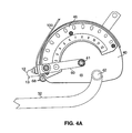
- the cam follower 69 is free to roll along the lower edge 13 of the stop bar 12. This is to accommodate the fore and aft movement of the cam arm 60 resulting from adjustment of the start position which can be observed in comparing Figures 4A and 4B.
- the stop position of the input assembly 30 is determined by a stop cam 80, best seen in Figures 1A and 1B.
- the stop cam 80 is mounted coaxially with the shaft 20 on rod 11 by bearings in a conventional manner.
- a handle 82 having a padded grip 83 is mounted to the outer perimeter of the stop cam 80 to facilitate easy rotation of the stop cam 80 about the rod 11.
- the stop cam 80 has holes 84, similar to the holes 48 in the cam plate 46, that are preferably spaced at equal intervals along the outer portion of the stop cam 80. However, unlike the holes 48 in the cam plate 46, the holes 84 in the stop cam 80 are each spaced the same distance from the pivot axis of the stop cam 80.
- the stop cam 80 has a stop member 85 which extends laterally from the side of the stop cam 80 proximate the input arm 32.
- the stop member 85 is positioned to interfere with the movement of the input arm 32 and may include a rubber bumper 86 or the like to cushion the impact of the input arm 32 against the stop member 85.
- the stop position of the input assembly 30 is determined by the rotational orientation of the stop cam 80 about rod 11 with respect to the input arm 32.
- the stop member 85 could alternatively contact a protrusion on the cam 40 or the shaft 20 and still practice the present invention, provided that the limit of rotation of the arm 32 is determined by such action.
- a second detent assembly comprising a sleeve 14 and a resiliently biased pin 16 is mounted to the frame 10 and positioned adjacent the stop cam 80 so as to be aligned with and engage the holes 84 in the stop cam 80.
- the orientation of the stop cam 80 can thereby be selectively fixed by a user by engaging the detent pin 16 in one of the holes 84. Accordingly, the user chooses the desired stop position by engaging detent pin 16 in one of the holes 84 to fix the orientation of the stop cam 80.
- the holes 84 in the stop cam 80 can be marked with alphanumeric characters to designate the stop position desired by the user.
- Detent pin 16 functions similar to cam arm detent pin 70, and likewise may be replaced by a regular pin, a latch or some other mechanical locking means
- the start position for the training exercise or rehabilitation protocol is set by a user by pulling knob 76 to overcome the biasing force of spring 74 and disengage pin 72 from one of the holes 48.
- This mechanically disconnects the cam arm 60 from the cam 40 which in turn results in the tether 100 (and weight stack 90) being mechanically separated from the cam 40 and input assembly 30.
- the user then rotates the input assembly 30 to the desired starting position.
- the input assembly 30, the cam 40, and the shaft 20 move freely together thereby maintaining the synchronization of the cam mechanical advantage to that of the user.
- cam arm 60 does not rotate during the adjustment because the detent pin 70 is disengaged from the cam 40.
- the weights 90 will not be lifted. This permits the user to adjust the start position without having to lift the weight stack 90.
- the user releases knob 76 and the pin 72 engages the selected hole 48.
- knob 18 To choose the stop position, the user pulls on knob 18 to disengage pin 16 from one of the holes 84. Once the user disengages detent pin 16 the user may rotate stop cam 80 to a desired stop position using handle 82. The user then releases the knob 18 to engage the pin 16 to one of the holes 84.
- the cam arm 60 always starts at the same position, i.e, with the cam follower 69 resting against stop bar 12.
- the device acts like a conventional selectorized variable resistance machine. Arm 60 is coupled with the cam 40 and moves with the cam 40 away from the stop bar 12, thereby providing resistance to the movement of the user.
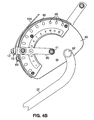
- Figures 6A and 6B illustrate the present invention shown in an exploded view as part of a leg extension exercise machine.
- the left hand side of Figure 6A is a continuation of the right hand side of Figure 6B.
- This embodiment uses detent pins 14 and 70, as in the first embodiment, to adjust the start and stop positions for the range of motion.
- the leg extension exercise machine includes an input assembly 30 and a cam 40 mounted to a shaft 20 which is pivotally mounted to the frame 10.
- the leg extension exercise machine has a cam arm 60 pivotally mounted to the cam 40 to maintain the tether (not shown) substantially tangential to the outer perimeter of the cam 40 throughout the allowable start position adjustment range and a stop bar 12 to limit the rotation of the cam arm 60.
- a stop cam 80 is pivotally mounted to the frame 10 coaxial with the shaft 20 as described in connection with the leg curl machine. However, because of the nature of the exercise to be performed, the above elements are oriented to resist rotation when the input assembly 30 is rotated upward rather than downward, i.e., when the user's legs are extended.
- Figures 7A and 7B show the present invention as part of a prone leg curl exercise machine.
- This machine functions similar to the leg extension machine in that it resists upward movement of the input assembly 30, however, the user support is designed to support the user in a prone position, thereby allowing the user to perform a prone leg curl.
- the user support of the prone leg curl machine comprises a chest pad 102, a thigh pad 104 and an arm support assembly 110, all mounted to the frame to support a user in a prone position.
- the arm support assembly includes arm pads 112, handles 114 and padded grips 116.
- the prone leg curl exercise machine functions in a similar manner to the previously described exercise machines.
- Figures 8A and 8B show the present invention as part of a back extension machine.
- this machine functions as the previous embodiments, however, the input assembly and user support are adapted to support a user in a sitting position and to resist the backward motion (i.e., extension) of the user's back.
- the input assembly 30 is positioned above the seat pad 4 and includes a back bar 38 adjustably mounted to the input arm 32.
- the back bar 38 has a back pad 39 mounted to it in order to cushion the user contact point.
- the user support has an adjustable foot support assembly 120, including foot plates 122, to provide a base for the user as the back extension is performed.
- the device of the present invention may be used on other weight machines which do not offer variable resistance to the user, such as machines where the cam is circular, and does not have a varying profile.
- any weight loading means on the machine may be used to place a load on the input assembly.
- a weight stack on a selectorized weight machine has been disclosed in the above embodiments for exemplary purposes.
- the present invention may be used on other exercise machines where a cam is rotated by an input assembly, for example, an arm curl machine, a rowing machine, etc.
Landscapes
- Health & Medical Sciences (AREA)
- Orthopedic Medicine & Surgery (AREA)
- General Health & Medical Sciences (AREA)
- Physical Education & Sports Medicine (AREA)
- Life Sciences & Earth Sciences (AREA)
- Biophysics (AREA)
- Rehabilitation Tools (AREA)
Applications Claiming Priority (2)
| Application Number | Priority Date | Filing Date | Title |
|---|---|---|---|
| US08/796,799 US5722921A (en) | 1997-02-06 | 1997-02-06 | Range limiting device for exercise equipment |
| US796799 | 1997-02-06 |
Publications (2)
| Publication Number | Publication Date |
|---|---|
| EP0857496A2 true EP0857496A2 (fr) | 1998-08-12 |
| EP0857496A3 EP0857496A3 (fr) | 1999-05-06 |
Family
ID=25169086
Family Applications (1)
| Application Number | Title | Priority Date | Filing Date |
|---|---|---|---|
| EP98300855A Withdrawn EP0857496A3 (fr) | 1997-02-06 | 1998-02-04 | Dispositif de limitation de la portée du mouvement des appareils d'exercices |
Country Status (2)
| Country | Link |
|---|---|
| US (1) | US5722921A (fr) |
| EP (1) | EP0857496A3 (fr) |
Cited By (5)
| Publication number | Priority date | Publication date | Assignee | Title |
|---|---|---|---|---|
| WO2015148925A1 (fr) * | 2014-03-28 | 2015-10-01 | Specialty Fitness Systems, Llc | Came ajustable pour équipement d'exercice |
| US10118073B2 (en) | 2016-04-04 | 2018-11-06 | Worldpro Group, LLC | Interactive apparatus and methods for muscle strengthening |
| US10478659B2 (en) | 2017-10-27 | 2019-11-19 | Christopher S. O'CONNOR | Dynamically variable radius cam for weight lifting apparatus |
| US11253741B2 (en) | 2017-03-07 | 2022-02-22 | Specialty Fitness Systems, Llc | Cam mechanism for adjustable torque without cable slack |
| WO2022238525A1 (fr) * | 2021-05-13 | 2022-11-17 | Epower Motors Aps | Machine de musculation motorisée |
Families Citing this family (67)
| Publication number | Priority date | Publication date | Assignee | Title |
|---|---|---|---|---|
| US7083554B1 (en) * | 1997-02-27 | 2006-08-01 | Nautilus, Inc. | Exercise machine with infinite position range limiter and automatic belt tensioning system |
| US7169093B2 (en) | 1999-09-14 | 2007-01-30 | Free Motion Fitness, Inc. | Cable crossover exercise apparatus |
| US6238323B1 (en) | 1999-09-14 | 2001-05-29 | The Simonson Family Limited Partnership Rlllp | Cable crossover exercise apparatus |
| US6302833B1 (en) | 2000-01-31 | 2001-10-16 | Northland Industries, Inc. | Multi-function exercise machine |
| US7608024B2 (en) * | 2000-03-06 | 2009-10-27 | Cybex International, Inc. | Multiple exercise apparatus having an adjustable arm mechanism |
| CA2402130C (fr) * | 2000-03-06 | 2009-05-12 | Scott Sechrest | Appareil d'entrainement fonctionnel |
| US7922635B2 (en) | 2000-03-10 | 2011-04-12 | Nautilus, Inc. | Adjustable-load unitary multi-position bench exercise unit |
| US7108641B2 (en) | 2000-05-03 | 2006-09-19 | Nautilus, Inc. | Exercise equipment with multi-positioning handles |
| US6565495B2 (en) * | 2001-02-14 | 2003-05-20 | J. Patrick Slattery | Ergonomic weightlifting bench |
| WO2003018138A1 (fr) * | 2001-08-28 | 2003-03-06 | John Michael Schopf | Appareil d'exercice |
| US6676574B1 (en) * | 2001-10-25 | 2004-01-13 | Brunswick Corporation | Shift position selector for a pad on an exercise machine |
| US20030092540A1 (en) * | 2001-11-13 | 2003-05-15 | Cybex International, Inc. | Range limiting device for exercise machine |
| US7070545B2 (en) | 2002-07-01 | 2006-07-04 | Nautilus, Inc. | Leg press and abdominal crunch exercise machine |
| US7070546B1 (en) | 2002-07-05 | 2006-07-04 | Joseph Grasso | Exercise apparatus including multiple function aspects and small footprint |
| US7115080B2 (en) | 2002-08-01 | 2006-10-03 | Nautilus, Inc. | Collapsible seat for combination hack squat and leg press machine |
| US7223213B2 (en) * | 2002-08-08 | 2007-05-29 | Nautilus, Inc. | Dual-direction pulley system |
| USD480773S1 (en) | 2002-11-13 | 2003-10-14 | Cybex International, Inc. | Weight stack support frame |
| US7758479B2 (en) * | 2004-07-22 | 2010-07-20 | Husted Royce H | Loading device for exercise machines |
| MX2007001799A (es) * | 2004-08-13 | 2007-09-14 | Wilfred Holness | Aparato para contracciones musculares isometricas e incrementales. |
| US7396319B1 (en) * | 2005-04-08 | 2008-07-08 | Northland Industries, Inc. | Inner and outer thigh exercise machine |
| US7601105B1 (en) | 2005-07-11 | 2009-10-13 | Icon Ip, Inc. | Cable crossover exercise apparatus with lateral arm movement |
| US7604576B2 (en) * | 2005-09-02 | 2009-10-20 | Drechsler Arthur J | Uniquely multi-functional exercise device |
| DE112006002705T5 (de) * | 2005-10-12 | 2008-08-21 | Magna Closures Inc., Newmarket | Verschlussdrehbetätigungsglied |
| US20080039297A1 (en) * | 2006-08-14 | 2008-02-14 | Zeev Steinmetz | Method and device to enable and assist the elderly and females to exercise their thigh and gluteus muscles |
| US20080064577A1 (en) * | 2006-09-11 | 2008-03-13 | Pederson Kim M | Exercise Device for Exercising Core Muscles |
| FR2910339B1 (fr) * | 2006-12-22 | 2009-03-20 | Stuart Lawrrence Shearer | Appareil de gymnastique convertible et banc de musculation correspondant. |
| US7537551B2 (en) * | 2007-01-22 | 2009-05-26 | Brunswick Corporation | Bidirectional resistance apparatus for exercise equipment |
| US20080261782A1 (en) * | 2007-01-23 | 2008-10-23 | Mark Campbell | Rowing Machine Simulators |
| US8608626B2 (en) | 2007-01-23 | 2013-12-17 | Rowperfect Pty Ltd | Rowing machine simulator |
| US7828706B2 (en) * | 2007-05-04 | 2010-11-09 | Medina Rafael R | Bilaterally actuated sculling trainer |
| EP2148729A2 (fr) * | 2007-05-11 | 2010-02-03 | D'Eredita, Michael | Machine à ramer simulée |
| US7955222B1 (en) * | 2007-09-06 | 2011-06-07 | Hernandez Rick S | Vertical jump training apparatus |
| US7850580B2 (en) * | 2007-12-07 | 2010-12-14 | Johnson Health Tech Co., Ltd. | Resistance exercise apparatus |
| US7833136B2 (en) * | 2008-01-12 | 2010-11-16 | Bell Edward J | Rowing trainer |
| US20090181830A1 (en) * | 2008-01-15 | 2009-07-16 | Super Made Products Co., Ltd. | Fitness treadmill |
| US7846074B2 (en) * | 2008-10-31 | 2010-12-07 | Strength Master Fitness Tech. Co., Ltd. | Recumbent exerciser |
| US8038588B2 (en) * | 2009-03-19 | 2011-10-18 | Rogers Athletic Company | Combined shoulder shrug and neck exercise machine |
| US7867154B2 (en) * | 2009-05-01 | 2011-01-11 | Teeter Roger C | Angle adjusting mechanism for tilting inversion exerciser |
| US20110034304A1 (en) * | 2009-08-05 | 2011-02-10 | Sports Art Industrial Co., Ltd. | Weight lifting exercising device |
| US9272179B2 (en) | 2009-10-26 | 2016-03-01 | The Personal Trainer, Inc. | Tension systems and methods of use |
| US8992385B2 (en) * | 2009-10-26 | 2015-03-31 | Personal Trainer, Inc. | Tension systems and methods of use |
| US7878957B1 (en) * | 2010-05-26 | 2011-02-01 | Yi-Fan Chen | Multi-functional exercising machine |
| TWI472357B (zh) * | 2011-11-11 | 2015-02-11 | Icon Ip Inc | 可調式腹部運動裝置 |
| US8876665B1 (en) * | 2012-04-30 | 2014-11-04 | Conner Athletic Products | Neck exercise machine for standing use |
| US9254409B2 (en) | 2013-03-14 | 2016-02-09 | Icon Health & Fitness, Inc. | Strength training apparatus with flywheel and related methods |
| EP3623020B1 (fr) | 2013-12-26 | 2024-05-01 | iFIT Inc. | Mécanisme de résistance magnétique dans une machine de câble |
| US10426989B2 (en) | 2014-06-09 | 2019-10-01 | Icon Health & Fitness, Inc. | Cable system incorporated into a treadmill |
| US9868016B2 (en) | 2015-01-12 | 2018-01-16 | Hoist Fitness Systems, Inc. | Exercise machine with a detachable stabilizing support assembly having adjustable positions |
| US10940360B2 (en) | 2015-08-26 | 2021-03-09 | Icon Health & Fitness, Inc. | Strength exercise mechanisms |
| TWI644702B (zh) | 2015-08-26 | 2018-12-21 | 美商愛康運動與健康公司 | 力量運動機械裝置 |
| JP6868012B2 (ja) | 2015-09-18 | 2021-05-12 | ジャキッシュ バイオメディカル コーポレーション | 運動装置用機器 |
| US10675497B2 (en) | 2015-09-18 | 2020-06-09 | Jaquish Biomedical Corporation | Devices for exercise apparatuses |
| US9630049B2 (en) * | 2015-09-21 | 2017-04-25 | Joseph D Hartman | Reciprocating rehabilitation device |
| US10212994B2 (en) | 2015-11-02 | 2019-02-26 | Icon Health & Fitness, Inc. | Smart watch band |
| US10441840B2 (en) | 2016-03-18 | 2019-10-15 | Icon Health & Fitness, Inc. | Collapsible strength exercise machine |
| US10293211B2 (en) | 2016-03-18 | 2019-05-21 | Icon Health & Fitness, Inc. | Coordinated weight selection |
| US10625137B2 (en) | 2016-03-18 | 2020-04-21 | Icon Health & Fitness, Inc. | Coordinated displays in an exercise device |
| US10493349B2 (en) | 2016-03-18 | 2019-12-03 | Icon Health & Fitness, Inc. | Display on exercise device |
| US10252109B2 (en) | 2016-05-13 | 2019-04-09 | Icon Health & Fitness, Inc. | Weight platform treadmill |
| US10661114B2 (en) | 2016-11-01 | 2020-05-26 | Icon Health & Fitness, Inc. | Body weight lift mechanism on treadmill |
| US10625114B2 (en) | 2016-11-01 | 2020-04-21 | Icon Health & Fitness, Inc. | Elliptical and stationary bicycle apparatus including row functionality |
| US11207556B2 (en) | 2018-07-23 | 2021-12-28 | Matthew Silveira | Competitive weightlifting machine and methods for using the same |
| US11154751B2 (en) * | 2020-02-20 | 2021-10-26 | Greg Bosch | Exercise apparatus |
| US12076610B2 (en) * | 2020-02-20 | 2024-09-03 | Greg Bosch | Exercise apparatus |
| CA3189214A1 (fr) * | 2022-02-11 | 2023-08-11 | Julien Leroux | Appareil d'exercice |
| TW202508671A (zh) * | 2023-05-05 | 2025-03-01 | 美商凱西爾公司 | 具有可旋轉凸輪的運動器材 |
| WO2025230766A1 (fr) * | 2024-05-01 | 2025-11-06 | Functional Patterns, Llc | Mécanisme permettant une commande de plage de mouvement pendant un exercice |
Citations (1)
| Publication number | Priority date | Publication date | Assignee | Title |
|---|---|---|---|---|
| US5102121A (en) | 1989-02-10 | 1992-04-07 | Lumex, Inc. | Device for limiting the range of motion on weight-lifting machines |
Family Cites Families (15)
| Publication number | Priority date | Publication date | Assignee | Title |
|---|---|---|---|---|
| US3856297A (en) * | 1972-03-20 | 1974-12-24 | J Schnell | Frictional type exercising device |
| US4200279A (en) * | 1978-04-05 | 1980-04-29 | Lambert Lloyd J Jr | Leg extension, leg curl, hip, thigh, back and buttocks machine |
| US4199139A (en) * | 1978-04-18 | 1980-04-22 | Marcy Gymnasium Equipment Co. | Exercising apparatus |
| US4311305A (en) * | 1979-12-04 | 1982-01-19 | Lambert Jr Lloyd J | Chest and bust machine |
| US4422636A (en) * | 1980-06-18 | 1983-12-27 | Angeli Michael M De | Exercise apparatus |
| US4411424A (en) * | 1982-02-08 | 1983-10-25 | Barnett Robert V | Weight lifting exercise apparatus |
| US4515363A (en) * | 1982-03-10 | 1985-05-07 | Schleffendorf John J | Weight lifting exerciser |
| US4793608A (en) * | 1984-05-09 | 1988-12-27 | Marcy Fitness Products | Exercise apparatus |
| US4621807A (en) * | 1984-05-25 | 1986-11-11 | Universal Gym Equipment, Inc. | Leg and hip exercising apparatus |
| DE3539796C2 (de) * | 1985-11-09 | 1994-05-05 | Josef Schnell | Trainingsgerät |
| US4709922A (en) * | 1986-01-21 | 1987-12-01 | Slade Jr James R | Barbell support apparatus for weight lifting exercising |
| US4763897A (en) * | 1986-09-05 | 1988-08-16 | Yakata Brian T | Exercise machine with adjustably positioned bar |
| US4836536A (en) * | 1987-06-11 | 1989-06-06 | Arthur Jones | Apparatus for exercising muscles of the lower trunk of the human body |
| US4842271A (en) * | 1988-05-24 | 1989-06-27 | Nautilus Sports/Medical Industries, Inc. | Leg extension exercise machine with leg length and exercise motion range adjustment apparatus |
| US5356360A (en) * | 1992-05-15 | 1994-10-18 | Titan Exercise Equipment, Inc. | Adjustable lever arm-variable resistance cam assembly |
-
1997
- 1997-02-06 US US08/796,799 patent/US5722921A/en not_active Expired - Lifetime
-
1998
- 1998-02-04 EP EP98300855A patent/EP0857496A3/fr not_active Withdrawn
Patent Citations (1)
| Publication number | Priority date | Publication date | Assignee | Title |
|---|---|---|---|---|
| US5102121A (en) | 1989-02-10 | 1992-04-07 | Lumex, Inc. | Device for limiting the range of motion on weight-lifting machines |
Cited By (10)
| Publication number | Priority date | Publication date | Assignee | Title |
|---|---|---|---|---|
| WO2015148925A1 (fr) * | 2014-03-28 | 2015-10-01 | Specialty Fitness Systems, Llc | Came ajustable pour équipement d'exercice |
| GB2539608A (en) * | 2014-03-28 | 2016-12-21 | Specialty Fitness Systems Llc | Adjustable CAM for exercise equipment |
| US10052515B2 (en) | 2014-03-28 | 2018-08-21 | Specialty Fitness Systems, Llc | Adjustable cam for exercise equipment |
| GB2539608B (en) * | 2014-03-28 | 2020-03-25 | Specialty Fitness Systems Llc | Adjustable cam for exercise equipment |
| US10118073B2 (en) | 2016-04-04 | 2018-11-06 | Worldpro Group, LLC | Interactive apparatus and methods for muscle strengthening |
| US10850162B2 (en) | 2016-04-04 | 2020-12-01 | Worldpro Group, L.L.C. | Interactive apparatus and methods for muscle strengthening |
| US11253741B2 (en) | 2017-03-07 | 2022-02-22 | Specialty Fitness Systems, Llc | Cam mechanism for adjustable torque without cable slack |
| US10478659B2 (en) | 2017-10-27 | 2019-11-19 | Christopher S. O'CONNOR | Dynamically variable radius cam for weight lifting apparatus |
| WO2022238525A1 (fr) * | 2021-05-13 | 2022-11-17 | Epower Motors Aps | Machine de musculation motorisée |
| US12403348B2 (en) | 2021-05-13 | 2025-09-02 | Epower Motors Aps | Motorized strength training machine |
Also Published As
| Publication number | Publication date |
|---|---|
| US5722921A (en) | 1998-03-03 |
| EP0857496A3 (fr) | 1999-05-06 |
Similar Documents
| Publication | Publication Date | Title |
|---|---|---|
| US5722921A (en) | Range limiting device for exercise equipment | |
| US20030092540A1 (en) | Range limiting device for exercise machine | |
| US5941807A (en) | Torso muscle and spine exercise apparatus | |
| US5277684A (en) | Multi-function exercise apparatus | |
| US7585263B2 (en) | Abdominal exercise machine | |
| US7717831B2 (en) | Torso exercise machine | |
| US4711448A (en) | Lower body exercising and weight training device | |
| EP2111268B1 (fr) | Dispositif d'exercice abdominal | |
| JP3750868B2 (ja) | 体力良好維持、リハビリテーションおよび治療のためのストレッチ療法器械 | |
| US7611445B2 (en) | Abdominal exercise machine | |
| US6387024B1 (en) | Device and method for kinesiologically correct exercise and rehabilitation | |
| AU584719B2 (en) | Exercise machines | |
| US4807874A (en) | Combination plantar flexion/dorsiflexion ankle machine | |
| US6746378B2 (en) | Lat pulldown weight training machine | |
| US7678033B2 (en) | Exercise equipment with system to position elastic bands to assist or oppose one another | |
| US5456644A (en) | Multiple station exercise machine having relocatable torsion resistance mechanisms | |
| US6544154B2 (en) | Variable resistance abdominal bench | |
| US6659919B2 (en) | Leg exerciser | |
| US5807219A (en) | Exercise apparatus adaptable for handicapped and non-handicapped users | |
| EP0060063A1 (fr) | Appareil et méthode d'exercice physique | |
| US20080058172A1 (en) | Exercise machine with manually operated pivoting rocker and with counterbalance arm configurable to assist or oppose movement of rocker | |
| US20040014570A1 (en) | Exercise bench | |
| CA2452373A1 (fr) | Exerciseur | |
| US5632710A (en) | Exercise apparatus | |
| US12491405B1 (en) | Lat pullover with pop pin adjustment |
Legal Events
| Date | Code | Title | Description |
|---|---|---|---|
| PUAI | Public reference made under article 153(3) epc to a published international application that has entered the european phase |
Free format text: ORIGINAL CODE: 0009012 |
|
| AK | Designated contracting states |
Kind code of ref document: A2 Designated state(s): AT BE CH DE DK ES FI FR GB GR IE IT LI NL PT SE |
|
| AX | Request for extension of the european patent |
Free format text: AL;LT;LV;MK;RO;SI |
|
| RIN1 | Information on inventor provided before grant (corrected) |
Inventor name: SIMONSON, ROY |
|
| PUAL | Search report despatched |
Free format text: ORIGINAL CODE: 0009013 |
|
| AK | Designated contracting states |
Kind code of ref document: A3 Designated state(s): AT BE CH DE DK ES FI FR GB GR IE IT LI LU MC NL PT SE |
|
| AX | Request for extension of the european patent |
Free format text: AL;LT;LV;MK;RO;SI |
|
| 17P | Request for examination filed |
Effective date: 19991109 |
|
| AKX | Designation fees paid |
Free format text: AT BE CH DE DK ES FI FR GB GR IE IT LI NL PT SE |
|
| STAA | Information on the status of an ep patent application or granted ep patent |
Free format text: STATUS: THE APPLICATION HAS BEEN WITHDRAWN |
|
| 18W | Application withdrawn |
Effective date: 20030326 |