EP0857557B1 - Hakenleiste - Google Patents
Hakenleiste Download PDFInfo
- Publication number
- EP0857557B1 EP0857557B1 EP98100934A EP98100934A EP0857557B1 EP 0857557 B1 EP0857557 B1 EP 0857557B1 EP 98100934 A EP98100934 A EP 98100934A EP 98100934 A EP98100934 A EP 98100934A EP 0857557 B1 EP0857557 B1 EP 0857557B1
- Authority
- EP
- European Patent Office
- Prior art keywords
- hooks
- hook
- holder bar
- tool
- holes
- Prior art date
- Legal status (The legal status is an assumption and is not a legal conclusion. Google has not performed a legal analysis and makes no representation as to the accuracy of the status listed.)
- Expired - Lifetime
Links
- 238000002347 injection Methods 0.000 claims abstract description 16
- 239000007924 injection Substances 0.000 claims abstract description 16
- 239000004033 plastic Substances 0.000 claims abstract description 14
- 229920003023 plastic Polymers 0.000 claims abstract description 14
- 238000001746 injection moulding Methods 0.000 claims description 16
- 238000000034 method Methods 0.000 claims description 13
- 239000011888 foil Substances 0.000 claims description 4
- 238000000465 moulding Methods 0.000 claims description 2
- 238000004519 manufacturing process Methods 0.000 abstract description 11
- 239000003000 extruded plastic Substances 0.000 abstract description 2
- 238000012432 intermediate storage Methods 0.000 abstract 1
- 238000004080 punching Methods 0.000 description 21
- 239000002184 metal Substances 0.000 description 10
- 239000000853 adhesive Substances 0.000 description 9
- 230000001070 adhesive effect Effects 0.000 description 9
- 230000008901 benefit Effects 0.000 description 5
- 238000010586 diagram Methods 0.000 description 3
- 238000002372 labelling Methods 0.000 description 3
- 238000005452 bending Methods 0.000 description 2
- 238000005520 cutting process Methods 0.000 description 2
- 238000003780 insertion Methods 0.000 description 2
- 230000037431 insertion Effects 0.000 description 2
- 238000005507 spraying Methods 0.000 description 2
- 238000006243 chemical reaction Methods 0.000 description 1
- 239000002131 composite material Substances 0.000 description 1
- 238000010924 continuous production Methods 0.000 description 1
- 230000000694 effects Effects 0.000 description 1
- 238000000605 extraction Methods 0.000 description 1
- 238000001125 extrusion Methods 0.000 description 1
- 238000009434 installation Methods 0.000 description 1
- 239000007788 liquid Substances 0.000 description 1
- 239000000463 material Substances 0.000 description 1
- 238000004806 packaging method and process Methods 0.000 description 1
- 239000000843 powder Substances 0.000 description 1
- 238000000926 separation method Methods 0.000 description 1
- 125000006850 spacer group Chemical group 0.000 description 1
- 239000007921 spray Substances 0.000 description 1
- 238000003860 storage Methods 0.000 description 1
Images

Classifications
-
- A—HUMAN NECESSITIES
- A47—FURNITURE; DOMESTIC ARTICLES OR APPLIANCES; COFFEE MILLS; SPICE MILLS; SUCTION CLEANERS IN GENERAL
- A47G—HOUSEHOLD OR TABLE EQUIPMENT
- A47G29/00—Supports, holders, or containers for household use, not provided for in groups A47G1/00-A47G27/00 or A47G33/00
- A47G29/10—Key holders; Key boards
-
- B—PERFORMING OPERATIONS; TRANSPORTING
- B29—WORKING OF PLASTICS; WORKING OF SUBSTANCES IN A PLASTIC STATE IN GENERAL
- B29C—SHAPING OR JOINING OF PLASTICS; SHAPING OF MATERIAL IN A PLASTIC STATE, NOT OTHERWISE PROVIDED FOR; AFTER-TREATMENT OF THE SHAPED PRODUCTS, e.g. REPAIRING
- B29C45/00—Injection moulding, i.e. forcing the required volume of moulding material through a nozzle into a closed mould; Apparatus therefor
- B29C45/14—Injection moulding, i.e. forcing the required volume of moulding material through a nozzle into a closed mould; Apparatus therefor incorporating preformed parts or layers, e.g. injection moulding around inserts or for coating articles
- B29C45/14336—Coating a portion of the article, e.g. the edge of the article
- B29C45/14344—Moulding in or through a hole in the article, e.g. outsert moulding
-
- B—PERFORMING OPERATIONS; TRANSPORTING
- B29—WORKING OF PLASTICS; WORKING OF SUBSTANCES IN A PLASTIC STATE IN GENERAL
- B29C—SHAPING OR JOINING OF PLASTICS; SHAPING OF MATERIAL IN A PLASTIC STATE, NOT OTHERWISE PROVIDED FOR; AFTER-TREATMENT OF THE SHAPED PRODUCTS, e.g. REPAIRING
- B29C45/00—Injection moulding, i.e. forcing the required volume of moulding material through a nozzle into a closed mould; Apparatus therefor
- B29C45/14—Injection moulding, i.e. forcing the required volume of moulding material through a nozzle into a closed mould; Apparatus therefor incorporating preformed parts or layers, e.g. injection moulding around inserts or for coating articles
- B29C45/1418—Injection moulding, i.e. forcing the required volume of moulding material through a nozzle into a closed mould; Apparatus therefor incorporating preformed parts or layers, e.g. injection moulding around inserts or for coating articles the inserts being deformed or preformed, e.g. by the injection pressure
- B29C2045/14237—Injection moulding, i.e. forcing the required volume of moulding material through a nozzle into a closed mould; Apparatus therefor incorporating preformed parts or layers, e.g. injection moulding around inserts or for coating articles the inserts being deformed or preformed, e.g. by the injection pressure the inserts being deformed or preformed outside the mould or mould cavity
- B29C2045/14245—Injection moulding, i.e. forcing the required volume of moulding material through a nozzle into a closed mould; Apparatus therefor incorporating preformed parts or layers, e.g. injection moulding around inserts or for coating articles the inserts being deformed or preformed, e.g. by the injection pressure the inserts being deformed or preformed outside the mould or mould cavity using deforming or preforming means outside the mould cavity
-
- B—PERFORMING OPERATIONS; TRANSPORTING
- B29—WORKING OF PLASTICS; WORKING OF SUBSTANCES IN A PLASTIC STATE IN GENERAL
- B29C—SHAPING OR JOINING OF PLASTICS; SHAPING OF MATERIAL IN A PLASTIC STATE, NOT OTHERWISE PROVIDED FOR; AFTER-TREATMENT OF THE SHAPED PRODUCTS, e.g. REPAIRING
- B29C65/00—Joining or sealing of preformed parts, e.g. welding of plastics materials; Apparatus therefor
- B29C65/02—Joining or sealing of preformed parts, e.g. welding of plastics materials; Apparatus therefor by heating, with or without pressure
- B29C65/08—Joining or sealing of preformed parts, e.g. welding of plastics materials; Apparatus therefor by heating, with or without pressure using ultrasonic vibrations
Definitions
- the invention relates to a hook strip according to claim 1, in particular for attaching of keys, with a body that has a plurality of hooks carries, as well as a device according to claim 7 and a method Claim 10 for producing such a hook bar.
- hook strips there are Bars punched out of sheet metal with the hooks bent out become. Such strips are processed in several steps and the manufacturing process in which the workpiece deburrs, degreases, phosphated and then either galvanized or powder coated is very expensive. Is with such hook strips intends to allow labeling of the hooks, so must separate fastening undercuts are formed on the bar are then inserted into the appropriate paper and film strips can be.
- metal rails are known, in which made of plastic sprayed hooks are pushed on from above. This is also very complex, because on the one hand to produce and rework the metal rail and on the other hand the assembly of the plastic hook must be made. A possibility of labeling the hooks is in this known embodiment via a corresponding Inscription groove on the hook released.
- Hook strips are also known, for example from GB-A-2,058,550, which are either made of plastic or metal and which are in mounting rails inserted, snapped or fastened in a similar manner are, but which all have a high installation effort.
- the object of the present invention is therefore a hook bar specify that with the least possible technical effort and before lowest possible labor costs due to Assembly or rework is to be made.
- the hook strips should can be made in any length without Changes to the geometry of the bar are necessary.
- the hook strip is an extruded profile made of plastic, which with a A plurality of perforations is provided, into which the plastic hook are positively injected.
- the advantage of the invention is that a hook bar according to the Invention can be produced purely by machine, without an additional manual processing would be necessary. So that is making one hook strip according to the invention very efficiently and can therefore very be carried out inexpensively.
- the extruded profile advantageously has the hook on it facing away from a shot on, in the additional elements can be included. This will make the Hook bar greatly increased.
- This recording is preferably around a T-groove, including this in the sense of the invention a dovetail groove is also to be understood, for example.
- the additional elements mentioned can be, for example to trade a metal rail.
- a simple, untreated metal strip thus stiffens the hook strip against bending and twist out.
- the hook bar is connected via the usually produced by injection molding, such as sliding blocks acting fastening body is preferably carried out on Fastening bodies designed snap hooks, hooking eyes, hooking undercuts or push-in knobs. These engage in corresponding Perforations of the locking bars. Alternatively, they are also to be made in perforations, notches, recesses etc., which may be directly in the front or back of key cabinets are trained.
- the advantage here is that there are different fastening bodies, so that the hook strip according to the invention to different Key cabinet systems is customizable.
- the hook bar itself will not changed.
- the manufacture of the fastening body is included Using simple injection molding tools, inexpensively using mold inserts to realize.
- the fastening body the hook bar is to be attached directly to a wall, either via Screws or an adhesive connection.
- screwing the fasteners are screwed to a wall as wall brackets and then inserted the bar sideways.
- the adhesive attachment is advantageously a cut profile in the as a recording acting T-slot of the hook strip and this then glued to a smooth wall with an adhesive strip.
- the back of the hook bar can also consist of several parallel grooves into which the fastening body then be clipped in accordingly.
- the injection mold can then still a cross-cut saw, with which in a continuous Production of hook strips in the desired length from the base body is to be separated.
- the crosscut saw can advantageously be used be carried by the base plate.
- the manufacturing method according to the invention possible: In this The process for producing a hook strip is made of plastic extruded profile cut to length and buffered in a magazine. From there it is fed to a punching tool, with which in perforations are made in the profile in a first operation The profile is then clocked into an injection mold in which the perforations come to lie in the area of cavities, so that in a further step in which the injection mold closes, hooks are injected here. This involves the insertion of holes and the spraying of hooks is repeated for one part at a time the hook of a hook bar to be manufactured.
- the hook strip quasi endlessly and then a hook bar with a cutting tool with a desired number of hooks or a desired number Detach length from this endless ledge.
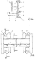
- a hook bar according to the invention is shown in cross section.
- a perforation 6 is provided, in which a hook 1 is molded directly.
- the hook is through the perforation 6 injected through and has on the other side of the profile 2 Widening 7, so that the hook 1 with the profile 2 connected is.
- the hook 1 is produced as described below will be described in such a way that its injection point 8 in one the later use of the hook bar not visible area lies.
- the hook strip shown here in section has 2 on its profile above the hook 1 on a paper / foil groove 4 in which a paper strip with a film strip 3 covering this is, so there is an easy way to hook 1 to label.
- Locking strips 40 are in key cabinets from various manufacturers available in different embodiments. The one shown here The shape of the locking strips has cutouts at regular intervals 41 on. The hook strips are in these cutouts 41 hooked with hangers 11, which on corresponding Fastening bodies 24 are formed, which in the T-groove 5 of the Profile 2 are inserted.
- the hook bar in such a hanging tab Punching 41 of the locking bar 40 is attached, it is down pulled and a also trained on the mounting body 24 Snap hook 12 is pressed into a further punch 41, with which the hook bar is fixed to the locking bar 40.
- the locking bar 40 with its cutouts 41 are also Fastening body 24 adapted accordingly.
- FIG. 5 shows another way of fastening a corresponding one Hook bar shown.
- additional elements fastening body in the form of Wall fasteners 20 inserted.
- Wall fasteners 20 inserted into the T-slot 5 as additional elements fastening body in the form of Wall fasteners 20 inserted.
- Wall fasteners 20 inserted into the T-slot 5 as additional elements fastening body in the form of Wall fasteners 20 inserted.
- These are wall mounts shown in more detail in FIG. They point to their front another screw countersink 21, so that here a countersunk screw is screwed in flush on the front.
- a hook bar pushed their T-slot 5, so that the hook bar in this way to be fixed to a wall with screws.
- end faces of the Finally, hook strips are provided with end caps 22, as they are also shown in Figure 6. Wear these end caps an insertion contour 23, the shape of which is matched to the T-slot 5 and is therefore held by it.
- FIG. 8 Another possibility of fastening is shown in FIG. 8: Here is an adhesive attachment 30 with appropriate hook bars 33 equipped, which engage in the T-slot 5. On the hook bar opposite side, the adhesive fastener 30 carries an adhesive strip 31, with which to attach a hook bar to a smooth surface is after the adhesive attachment into the T-slot as mentioned above 5 is used. Optionally, such an adhesive attachment 30 through a mounting punch hole 32 with a screw be fixed.
- the additional elements described, such as the wall bracket 20, the Fastening body 24 or the adhesive fastener 30 are described as nuts Fastening body preferably made of plastic in the Injection molding process made.
- the Hook strips on various key cabinet systems or others Use cases to be coordinated. This is just an exchange of the corresponding mounting body necessary without the key bar according to the invention is to be changed for this.
- a strip made of a metal strip can also be inserted, which stiffens the bar against bending and torsion. This metal strip can be cheap from untreated metal as it is cannot be seen.
- the geometry of the hook or the illustrated in the drawings can only be seen as an example. Basically, can Example, the paper groove can be placed above or below the hook and the cross section of the profile can have almost any geometry have, the fastening body, if necessary, the hook bar can also completely or partially encompass from the outside.
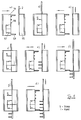
- the profile 2 is introduced into a follow-on tool, which consists of two parts that can be moved towards one another, namely a nozzle side 115 and an ejector side 116.
- the first hook bar is finished with the example shown here six hooks and can be removed from the tool.
- the second profile 2 is shown in FIG. 9c Position of the first profile moved in the same way as in the position shown in Figure 9d also on the second profile hook be molded on. That way is a continuous one Manufacturing process realized.
- hook strips produced in this way have a variety of benefits.
- there can be an optically appealing design in which, for example, colored hooks are molded.
- hooks can also be on the color of key fobs etc. be coordinated.
- the punching process described is a schematic diagram. There are also several options around the punching process to operate in the injection molding machine:
- a hydraulic cylinder controlled by the machine is possible to be provided in the movable plate of the form that after the application of the tool clamping force, i.e. when the tool is closed Tool, only initiates the punching process. This corresponds to that hydraulic ejector not described here in the Injection molding machine.
- a hydraulically or pneumatically operated Punching unit are provided, which then engages around the profile, whereby one is independent of the closing force.
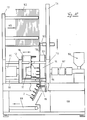
- FIG. 10 shows a complete system for producing a corresponding one Hook bar shown schematically:
- This device has a strip magazine 101, in which raw strips 102 are stored are. These raw strips are extruded in the shape of profile 2.
- the raw strips 102 are corresponding to the feed 103 in the Leistenmagazin 101 conveyed to an extraction point, where it from can be removed from the strip magazine by a gripper 105 which can be moved along an NC axis 104. According to that The process described in FIG. 9 becomes the raw strips with holes 6 and then with hook 1, which in these holes 6 are positively injected.
- This injection takes place via a device assigned to the device Injection molding machine.
- a funnel 106 becomes more suitable Plastic removed and heated in a heater 107 to then when injected through an injection cylinder 114 into the nozzle side 115 of the follow-up tool to be injected.
- the nozzle side 115 is opposite to the ejector side 116, wherein The shape of the hook 1 can be determined via the slide 117.
- the Ejector side 116 is on a movable platen attached along spars 111 by the closing hydraulics 110 is moved back and forth.
- the nozzle side 115 is on one fixed platen 113 rigidly attached.
- the most varied hook shapes are with this method producible in addition to hanging key fobs with hanging hole, paper and foil also for hanging of towels, washing-up brushes or similar items Hanging eyelet can be used.
- the dimensions of the Bars are variable, so that for example bars for hotel key rings can be manufactured with larger dimensions.
Landscapes
- Engineering & Computer Science (AREA)
- Manufacturing & Machinery (AREA)
- Mechanical Engineering (AREA)
- Moulds For Moulding Plastics Or The Like (AREA)
- Injection Moulding Of Plastics Or The Like (AREA)
- Slide Fasteners, Snap Fasteners, And Hook Fasteners (AREA)
- Hooks, Suction Cups, And Attachment By Adhesive Means (AREA)
- Perforating, Stamping-Out Or Severing By Means Other Than Cutting (AREA)
- Supports Or Holders For Household Use (AREA)
Description
- Figur 1
- einen Schnitt durch eine erfindungsgemäße Hakenleiste entlang der Schnittlinie I-I in Figur 2;
- Figur 2
- die Vorderansicht einer erfindungsgemäßen Hakenleiste befestigt an zwei Rastleisten;
- Figur 3
- eine Aufsicht auf die Befestigung einer Hakenleiste an einer Rastleiste gemäß Figur 2;
- Figur 4
- einen Schnitt entlang der Befestigung einer Hakenleiste an einer Rastleiste gemäß der Linie IV-IV in Figur 2;
- Figur 5
- die Vorderansicht einer Hakenleiste mit einer anderen Befestigungsweise;
- Figuren 6 bis 8
- Ansichten verschiedener Zubehörteile für eine Hakenleiste;
- Figur 9
- Prinzipskizze der schrittweisen Herstellung einer erfindungsgemäßen Hakenleiste;
- Figur 10
- Prinzipskizze einer Vorrichtung zur Herstellung einer erfindungsgemäßen Hakenleiste.

Claims (11)
- Hakenleiste, insbesondere zum Anhängen von Schlüsseln, mit einem Grundkörper, der eine Mehrzahl von Haken trägt,
dadurch gekennzeichnet,daß der Grundkörper ein extrudiertes Profil (2) aus Kunststoff ist, das mit einer Mehrzahl von Lochungen (6) versehen ist, in die die Haken (1) aus Kunststoff formschlüssig angespritzt sind. - Hakenleiste gemäß Anspruch 1,
dadurch gekennzeichnet,daß die angespritzten Haken (1) die Lochungen (6) in dem extrudierten Profil (2) mit einstückig angeformten Aufweitungen (7) umgreifen. - Hakenleiste gemäß Anspruch 1,
dadurch gekennzeichnet,daß das extrudierte Profil (2) an seiner dem Haken abgewandten Rückseite eine Aufnahme für Zusatzelemente aufweist. - Hakenleiste gemäß Anspruch 3,
dadurch gekennzeichnet,daß die Aufnahme eine T-Nut (5) ist. - Hakenleiste gemäß Anspruch 3,
dadurch gekennzeichnet, daß das Zusatzelement eine Metallschiene ist. - Hakenleiste gemäß Anspruch 3,
dadurch gekennzeichnet,daß das Zusatzelement ein Befestigungskörper (24, 20, 30) ist. - Vorrichtung zum Herstellen einer Hakenleiste nach Anspruch 1mit einer Zuführung für einen extrudierten Grundkörper (2), einem Stanzwerkzeug zum Einbringen von Lochungen in den Grundkörper undeinem Spritzgußwerkzeug mit Kavitäten zum Anformen von Haken (1) an den Grundkörper (2),wobei das Stanzwerkzeug und das Spritzgußwerkzeug von einer gemeinsamen Grundplatte (120) getragen sind.
- Vorrichtung gemäß Anspruch 7,
dadurch gekennzeichnet,daß dem Spritzwerkzeug eine Ablängsäge (119) nachgeordnet ist. - Vorrichtung gemäß Anspruch 8,
dadurch gekennzeichnet,daß die Ablängsäge (119) von der Grundplatte (120) getragen ist. - Verfahren zum Herstellen einer Hakenleiste nach Anspruch 1,bei dem ein aus Kunststoff extrudiertes Profil (2) abgelängt und in einem Magazin zwischengespeichert wird, von dort einem Stanzwerkzeug zugeführt wird, mit dem in einem Arbeitsgang Lochungen (6) in das Profil eingebracht werden, das Profil (2) dann in ein Spritzwerkzeug weitergetaktet wird, in dem die Lochungen (6) im Bereich von Kavitäten zu liegen kommen, und in einem weiteren Arbeitsgang hier Haken (1) angespritzt werden, wobei das Einbringen von Lochungen und das Anspritzen von Haken wiederholt erfolgt für jeweils einen Abschnitt der zu fertigenden Hakenleiste.
- Verfahren gemäß Anspruch 10,
dadurch gekennzeichnet,daß Aufnahmetaschen für Papier und/oder Folie an oder neben den Haken mit angespritzt werden.
Applications Claiming Priority (2)
| Application Number | Priority Date | Filing Date | Title |
|---|---|---|---|
| DE19704239 | 1997-02-05 | ||
| DE19704239A DE19704239C1 (de) | 1997-02-05 | 1997-02-05 | Hakenleiste |
Publications (2)
| Publication Number | Publication Date |
|---|---|
| EP0857557A1 EP0857557A1 (de) | 1998-08-12 |
| EP0857557B1 true EP0857557B1 (de) | 1999-12-29 |
Family
ID=7819322
Family Applications (1)
| Application Number | Title | Priority Date | Filing Date |
|---|---|---|---|
| EP98100934A Expired - Lifetime EP0857557B1 (de) | 1997-02-05 | 1998-01-21 | Hakenleiste |
Country Status (5)
| Country | Link |
|---|---|
| EP (1) | EP0857557B1 (de) |
| AT (1) | ATE188164T1 (de) |
| DE (1) | DE19704239C1 (de) |
| ES (1) | ES2141623T3 (de) |
| PT (1) | PT857557E (de) |
Families Citing this family (4)
| Publication number | Priority date | Publication date | Assignee | Title |
|---|---|---|---|---|
| EP0970645A2 (de) | 1998-06-25 | 2000-01-12 | Erwin Paulat Kunststoff- und Metallwaren GmbH | Hakenleiste |
| DE10302253B3 (de) * | 2003-01-22 | 2004-04-15 | Erwin Paulat Kunststoff- Und Metallwaren Gmbh | Wandschrank aus einstückigen Blechkorpussen |
| DE10341495B4 (de) * | 2003-09-04 | 2005-06-23 | "Durable" Hunke & Jochheim Gmbh & Co. Kg | Schlüsselleiste |
| CN116748853B (zh) * | 2023-08-07 | 2025-12-12 | 宿迁臻易智能装备制造有限公司 | 无痕钉挂钩自动装配机构 |
Family Cites Families (7)
| Publication number | Priority date | Publication date | Assignee | Title |
|---|---|---|---|---|
| GB1205125A (en) * | 1967-04-18 | 1970-09-16 | Meyer Joseph Ragir | Support devices |
| GB2058550A (en) * | 1979-09-12 | 1981-04-15 | Kitson R A | Key cabinets |
| US4326761A (en) * | 1979-12-10 | 1982-04-27 | Samuel Schwartz | Key and lock core combination |
| EP0221851B1 (de) * | 1985-11-06 | 1991-12-27 | Ego Kunststoffwerk Ag | Verfahren und Vorrichtung zur Herstellung eines flexiblen Gliederbandes |
| JPH07156194A (ja) * | 1993-12-10 | 1995-06-20 | Toshiba Corp | アウトサート成形品 |
| FR2731893B1 (fr) * | 1995-03-20 | 1997-05-09 | Carpentier Jean Luc | Dispositif d'accrochage mural pour elements tels que serviettes ou torchons |
| JP3427556B2 (ja) * | 1995-03-30 | 2003-07-22 | 日立電線株式会社 | 射出成形回路部品の製造方法 |
-
1997
- 1997-02-05 DE DE19704239A patent/DE19704239C1/de not_active Expired - Fee Related
-
1998
- 1998-01-21 AT AT98100934T patent/ATE188164T1/de not_active IP Right Cessation
- 1998-01-21 PT PT98100934T patent/PT857557E/pt unknown
- 1998-01-21 EP EP98100934A patent/EP0857557B1/de not_active Expired - Lifetime
- 1998-01-21 ES ES98100934T patent/ES2141623T3/es not_active Expired - Lifetime
Also Published As
| Publication number | Publication date |
|---|---|
| ATE188164T1 (de) | 2000-01-15 |
| ES2141623T3 (es) | 2000-03-16 |
| PT857557E (pt) | 2000-05-31 |
| DE19704239C1 (de) | 1998-08-27 |
| EP0857557A1 (de) | 1998-08-12 |
Similar Documents
| Publication | Publication Date | Title |
|---|---|---|
| DE69204656T2 (de) | Verfahren zum Herstellen von Zahnbürsten. | |
| DE10164900B4 (de) | Formschließvorrichtung für eine Spritzgießmaschine | |
| EP2502723B1 (de) | Verfahren zur Herstellung von faserverstärkten, Anbauelemente umfassenden Innenverkleidungsbauteilen für Kraftfahrzeuge | |
| EP1986835B1 (de) | Verfahren und spritzgiesswerkzeug zum herstellen einer faserverbundstruktur | |
| EP0934152B1 (de) | Verfahren und vorrichtung zum einfassen von decormaterial | |
| DE102012024056A1 (de) | Verfahren zur Herstellung eines Kunststoffbauteils und Spritzgießwerkzeug zur Durchführung des Verfahrens | |
| EP0421089B1 (de) | Verfahren zum örtlich definierten, festhaftenden Anbringen von Kunststoff-Kleinteilen an im wesentlichen aus verklebten oder kunstharzgebundenen Naturfasern oder Spänen bestehenden Formpressteilen | |
| EP2070680B1 (de) | Verfahren und Vorrichtung zur Herstellung eines Formteils mit mehreren aneinandergrenzenden, unterschiedlichen Dekorbereichen | |
| EP0161589B1 (de) | Verfahren und Vorrichtung zum Herstellen eines Kunststoff Spritzgussteils, insbesondere Profilleiste für Fahrzeuge | |
| EP3585587B1 (de) | Verfahren zum herstellen eines haushaltsgerätebauteils in einem kombinierten spritzgussprozess mit einem dünnwandspritzgiessen und einem kaskaden-spritzgiessen sowie haushaltsgerätebauteil | |
| DE19704239C1 (de) | Hakenleiste | |
| EP2024164B1 (de) | Verfahren und vorrichtung zum herstellen eines kaschierten formteils | |
| DE19627176C2 (de) | Vorrichtung zum Spritzgießen mit auswechselbaren Formleisten | |
| EP0914238B1 (de) | Verfahren und vorrichtung zur herstellung von beweglichen elementen eines kunststoffbauteils | |
| DE19727786C2 (de) | Verfahren und Werkzeug zum Spritzgießen von Gegenständen | |
| DE3405001A1 (de) | Verfahren zur herstellung von buersten, besen und dergleichen | |
| DE2801411C3 (de) | Verfahren zur Herstellung eines Formlings, z.B. als Halter für Etiketten an Bekleidungsstücken, und Spritzgießform zur Durchführung des Verfahrens | |
| DE102007053123A1 (de) | Werkzeug zum Spritzgießen von Kunststoffteilen | |
| DE102017106490B4 (de) | Verfahren und Vorrichtung zur Herstellung eines Formteils mit einem faserverstärkten Träger und mindestens einem damit verbundenen, Kunststoff aufweisenden Anbauteil | |
| DE4213466C2 (de) | Verfahren zum Herstellen von Profilleisten | |
| DE10226982B4 (de) | Zierteilemagazin sowie Verfahren und Vorrichtung zu seiner Herstellung | |
| DE102010034096A1 (de) | Vorrichtung zum Herstellen von Hinterfüllten Dekorteilen | |
| EP1090735A2 (de) | Verfahren und Vorrichtung zum Thermoformen von Behältern | |
| DE1729181C (de) | Spritzgießform zur Herstellung eines Borsten tragenden Gegenstandes | |
| DE3742416A1 (de) | Verfahren und vorrichtung zum herstellen eines profilstabes aus thermoplastischem kunststoff |
Legal Events
| Date | Code | Title | Description |
|---|---|---|---|
| PUAI | Public reference made under article 153(3) epc to a published international application that has entered the european phase |
Free format text: ORIGINAL CODE: 0009012 |
|
| AK | Designated contracting states |
Kind code of ref document: A1 Designated state(s): AT CH ES FR GB IT LI NL PT SE |
|
| AX | Request for extension of the european patent |
Free format text: AL;LT;LV;MK;RO;SI |
|
| 17P | Request for examination filed |
Effective date: 19980722 |
|
| AKX | Designation fees paid |
Free format text: AT CH ES FR GB IT LI NL PT SE |
|
| RBV | Designated contracting states (corrected) |
Designated state(s): AT CH ES FR GB IT LI NL PT SE |
|
| GRAG | Despatch of communication of intention to grant |
Free format text: ORIGINAL CODE: EPIDOS AGRA |
|
| REG | Reference to a national code |
Ref country code: DE Ref legal event code: 8566 |
|
| 17Q | First examination report despatched |
Effective date: 19990518 |
|
| GRAG | Despatch of communication of intention to grant |
Free format text: ORIGINAL CODE: EPIDOS AGRA |
|
| GRAH | Despatch of communication of intention to grant a patent |
Free format text: ORIGINAL CODE: EPIDOS IGRA |
|
| GRAH | Despatch of communication of intention to grant a patent |
Free format text: ORIGINAL CODE: EPIDOS IGRA |
|
| GRAA | (expected) grant |
Free format text: ORIGINAL CODE: 0009210 |
|
| AK | Designated contracting states |
Kind code of ref document: B1 Designated state(s): AT CH ES FR GB IT LI NL PT SE |
|
| REF | Corresponds to: |
Ref document number: 188164 Country of ref document: AT Date of ref document: 20000115 Kind code of ref document: T |
|
| REG | Reference to a national code |
Ref country code: CH Ref legal event code: EP |
|
| REG | Reference to a national code |
Ref country code: CH Ref legal event code: NV Representative=s name: R. A. EGLI & CO. PATENTANWAELTE |
|
| GBT | Gb: translation of ep patent filed (gb section 77(6)(a)/1977) |
Effective date: 20000118 |
|
| ITF | It: translation for a ep patent filed | ||
| PGFP | Annual fee paid to national office [announced via postgrant information from national office to epo] |
Ref country code: SE Payment date: 20000215 Year of fee payment: 3 |
|
| REG | Reference to a national code |
Ref country code: ES Ref legal event code: FG2A Ref document number: 2141623 Country of ref document: ES Kind code of ref document: T3 |
|
| ET | Fr: translation filed | ||
| REG | Reference to a national code |
Ref country code: PT Ref legal event code: SC4A Free format text: AVAILABILITY OF NATIONAL TRANSLATION Effective date: 20000302 |
|
| PLBE | No opposition filed within time limit |
Free format text: ORIGINAL CODE: 0009261 |
|
| STAA | Information on the status of an ep patent application or granted ep patent |
Free format text: STATUS: NO OPPOSITION FILED WITHIN TIME LIMIT |
|
| PGFP | Annual fee paid to national office [announced via postgrant information from national office to epo] |
Ref country code: PT Payment date: 20001124 Year of fee payment: 4 |
|
| 26N | No opposition filed | ||
| PGFP | Annual fee paid to national office [announced via postgrant information from national office to epo] |
Ref country code: AT Payment date: 20010130 Year of fee payment: 4 |
|
| PG25 | Lapsed in a contracting state [announced via postgrant information from national office to epo] |
Ref country code: SE Free format text: LAPSE BECAUSE OF NON-PAYMENT OF DUE FEES Effective date: 20010131 |
|
| REG | Reference to a national code |
Ref country code: GB Ref legal event code: IF02 |
|
| PG25 | Lapsed in a contracting state [announced via postgrant information from national office to epo] |
Ref country code: GB Free format text: LAPSE BECAUSE OF NON-PAYMENT OF DUE FEES Effective date: 20020121 Ref country code: AT Free format text: LAPSE BECAUSE OF NON-PAYMENT OF DUE FEES Effective date: 20020121 |
|
| PG25 | Lapsed in a contracting state [announced via postgrant information from national office to epo] |
Ref country code: LI Free format text: LAPSE BECAUSE OF NON-PAYMENT OF DUE FEES Effective date: 20020131 Ref country code: CH Free format text: LAPSE BECAUSE OF NON-PAYMENT OF DUE FEES Effective date: 20020131 |
|
| PG25 | Lapsed in a contracting state [announced via postgrant information from national office to epo] |
Ref country code: PT Free format text: LAPSE BECAUSE OF NON-PAYMENT OF DUE FEES Effective date: 20020731 |
|
| GBPC | Gb: european patent ceased through non-payment of renewal fee |
Effective date: 20020121 |
|
| REG | Reference to a national code |
Ref country code: CH Ref legal event code: PL |
|
| PGFP | Annual fee paid to national office [announced via postgrant information from national office to epo] |
Ref country code: FR Payment date: 20021030 Year of fee payment: 6 |
|
| REG | Reference to a national code |
Ref country code: PT Ref legal event code: MM4A Free format text: LAPSE DUE TO NON-PAYMENT OF FEES Effective date: 20020731 |
|
| PGFP | Annual fee paid to national office [announced via postgrant information from national office to epo] |
Ref country code: NL Payment date: 20030120 Year of fee payment: 6 |
|
| PGFP | Annual fee paid to national office [announced via postgrant information from national office to epo] |
Ref country code: ES Payment date: 20030130 Year of fee payment: 6 |
|
| PG25 | Lapsed in a contracting state [announced via postgrant information from national office to epo] |
Ref country code: ES Free format text: LAPSE BECAUSE OF NON-PAYMENT OF DUE FEES Effective date: 20040122 |
|
| PG25 | Lapsed in a contracting state [announced via postgrant information from national office to epo] |
Ref country code: NL Free format text: LAPSE BECAUSE OF NON-PAYMENT OF DUE FEES Effective date: 20040801 |
|
| PG25 | Lapsed in a contracting state [announced via postgrant information from national office to epo] |
Ref country code: FR Free format text: LAPSE BECAUSE OF NON-PAYMENT OF DUE FEES Effective date: 20040930 |
|
| NLV4 | Nl: lapsed or anulled due to non-payment of the annual fee |
Effective date: 20040801 |
|
| REG | Reference to a national code |
Ref country code: FR Ref legal event code: ST |
|
| PG25 | Lapsed in a contracting state [announced via postgrant information from national office to epo] |
Ref country code: IT Free format text: LAPSE BECAUSE OF NON-PAYMENT OF DUE FEES;WARNING: LAPSES OF ITALIAN PATENTS WITH EFFECTIVE DATE BEFORE 2007 MAY HAVE OCCURRED AT ANY TIME BEFORE 2007. THE CORRECT EFFECTIVE DATE MAY BE DIFFERENT FROM THE ONE RECORDED. Effective date: 20050121 |
|
| REG | Reference to a national code |
Ref country code: ES Ref legal event code: FD2A Effective date: 20040122 |