EP0857617A2 - Vielfachterminal und elektrische Verbindungsdose die diesen verwendet - Google Patents
Vielfachterminal und elektrische Verbindungsdose die diesen verwendet Download PDFInfo
- Publication number
- EP0857617A2 EP0857617A2 EP98102113A EP98102113A EP0857617A2 EP 0857617 A2 EP0857617 A2 EP 0857617A2 EP 98102113 A EP98102113 A EP 98102113A EP 98102113 A EP98102113 A EP 98102113A EP 0857617 A2 EP0857617 A2 EP 0857617A2
- Authority
- EP
- European Patent Office
- Prior art keywords
- terminal
- substrate
- junction box
- pressure
- contact
- Prior art date
- Legal status (The legal status is an assumption and is not a legal conclusion. Google has not performed a legal analysis and makes no representation as to the accuracy of the status listed.)
- Withdrawn
Links
- 239000000758 substrate Substances 0.000 claims abstract description 63
- 230000000149 penetrating effect Effects 0.000 claims description 3
- 239000002184 metal Substances 0.000 description 4
- 230000007423 decrease Effects 0.000 description 3
- 241000237519 Bivalvia Species 0.000 description 1
- 238000005452 bending Methods 0.000 description 1
- 235000020639 clam Nutrition 0.000 description 1
- 239000011810 insulating material Substances 0.000 description 1
- 238000009413 insulation Methods 0.000 description 1
- 238000012856 packing Methods 0.000 description 1
- 239000002356 single layer Substances 0.000 description 1
Images

Classifications
-
- B—PERFORMING OPERATIONS; TRANSPORTING
- B60—VEHICLES IN GENERAL
- B60R—VEHICLES, VEHICLE FITTINGS, OR VEHICLE PARTS, NOT OTHERWISE PROVIDED FOR
- B60R16/00—Electric or fluid circuits specially adapted for vehicles and not otherwise provided for; Arrangement of elements of electric or fluid circuits specially adapted for vehicles and not otherwise provided for
- B60R16/02—Electric or fluid circuits specially adapted for vehicles and not otherwise provided for; Arrangement of elements of electric or fluid circuits specially adapted for vehicles and not otherwise provided for electric constitutive elements
- B60R16/023—Electric or fluid circuits specially adapted for vehicles and not otherwise provided for; Arrangement of elements of electric or fluid circuits specially adapted for vehicles and not otherwise provided for electric constitutive elements for transmission of signals between vehicle parts or subsystems
- B60R16/0238—Electrical distribution centers
-
- H—ELECTRICITY
- H01—ELECTRIC ELEMENTS
- H01R—ELECTRICALLY-CONDUCTIVE CONNECTIONS; STRUCTURAL ASSOCIATIONS OF A PLURALITY OF MUTUALLY-INSULATED ELECTRICAL CONNECTING ELEMENTS; COUPLING DEVICES; CURRENT COLLECTORS
- H01R9/00—Structural associations of a plurality of mutually-insulated electrical connecting elements, e.g. terminal strips or terminal blocks; Terminals or binding posts mounted upon a base or in a case; Bases therefor
- H01R9/22—Bases, e.g. strip, block, panel
- H01R9/24—Terminal blocks
- H01R9/2458—Electrical interconnections between terminal blocks
Definitions
- the present Invention relates to a multi-terminal for making a branched circuit connection in an electrical junction box, especially for use in an automobile.
- the multi-terminal allows the electrical junction box to be more compact and to facilitate assembly.
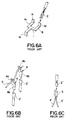
- busbar 1 has been formed by stamping a conductive metal plate from sheet metal. It is part of the internal electrical circuit and comprises branched portions 1a and 1b which are bent to form tabs 1c and 1d, respectively. Tab 1e is connected to the internal circuit of the junction box, while tabs 1c and 1d are used to form a connection with pressure terminal 2. Pressure terminal 2 is connected to an external circuit.
- Wire 3 which is a single core wire, is connected by means of pressure connector terminal 4 to pressure terminal 2' of the external circuit.
- Pressure terminal 4 comprises pressure connection blade 4a and a tab 4b, blade 4a being used to cut the insulation of wire 3 and to make electrical contact with the conductive core of the wire.
- Tab 4b which is formed on the other side of pressure connection terminal 4, connects to pressure terminal 2' which, in turn, is in contact with the external circuit.
- FIG. 6C A third conventional structure employed to make a branched circuit in an electrical junction box is shown in Figure 6C.
- a plurality of wires 4' are joined by means of a female pressure terminal 5 to a male pressure terminal 2''.
- wires 4' are connected to an internal circuit while male pressure terminal 2'' is connected to the external circuit.
- Another problem associated with this coplanar arrangement is that it is difficult to position connections in a vertically offset manner. In other words, it is desirable to have a 3-dimensional terminal rather than a coplanar terminal in order to allow for high density packing of circuits.
- a further problem associated with these conventional structures is they are not suited for use with a printed substrate which contains electrical devices such as diodes.
- These printed electrical substrates are typically in sheet form and, in order to connect the circuitry of the substrate to one of the conventional structures as taught in Figures 6A-6C, a wire must be connected specifically from the electrical circuitry in the substrate to one of the aforementioned structures. This added wire also increases the number of electrical connections in the junction box and decreases the ability to make it more densely packed.
- the present Invention solves a number of the drawbacks associated with the prior art structures for forming branch connections in electrical junction boxes.
- the present Invention is a multi-terminal that provides connections with the printed circuit on a substrate, a single core wire from the internal circuitry of the junction box, and the tab of a busbar or the terminal of an external circuit.
- the multi-terminal also provides 3-dimensional branching connections that allow for compact design of the internal structure of the box.
- the wire pressure contact portion of the multi-terminal projects from one side of the upper end of the common substrate. It is also preferred that the substrate connecting portion is on the side of the upper end of the common substrate opposite the wire pressure contact portion. In this arrangement, the other end of the common substrate is bent to provide a position for the substrate connecting portion. It is further preferred that the terminal fitting connection project from the bottom end of the common substrate.
- the substrate connecting portion projecting in the opposite direction from the wire pressure contact portion. It should also be noted that both the number and direction of the wire pressure contact portion, the substrate connection portion, and the terminal fitting portion, as formed on the common substrate, are not restricted in any manner.
- the electrical junction box comprises upper and lower cases, which hold single core wires for the internal circuitry, and a printed substrate on which are mounted electrical devices; the junction box employs the multi-terminal of the present Invention in order to make branched connections between the various circuits.
- a busbar can be molded into the upper case and/or the lower case and can connect to the multi-terminal of the present Invention.
- the substrate connection portion of the multi-terminal has a tab which pierces the insulated portion of the printed substrate and contacts the circuit. It is then soldered to form the connection.
- the terminal fitting portion of the multi-terminals is inserted into a terminal opening of a connector fitting portion in the junction box and is connected to a pressure terminal from an external circuit.
- the wire pressure contact portion is pressure connected to a single core wire of the internal circuit.
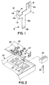
- multi-terminal 10 is formed by stamping and then bending common substrate 11 from a conductive metal plate.
- Multi-terminal 10 comprises wire pressure contact portion 12, terminal fitting connector 13, and substrate connecting portion 14.
- Wire pressure contact portion 12 comprises an open pressure contact blade 12a which projects from one side of the upper end of common substrate 11.
- Pressure contact blade 12a is used to cut through the insulating material around the wire so as to contact the wire core.
- Terminal fitting connector 13 comprises flat plate projection 13a which projects from the lower end of common substrate 11 and terminates in male end tab 13b.
- On the other side of common substrate 11 is a bend and a right angle constituting substrate connecting portion 14.
- Substrate connecting portion 14 comprises long, thin projection 14a which projects from the upper end of bend 11a and piercing portion 14b is at the end of projection 14a.
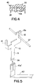
- Figure 2 illustrates how multi-terminal 10 is used in junction box case 20.
- Case 20 has bottom wall 21 and connector fitting portion 22 thereon; multi-terminal 10 is disposed on the inner surface of connector fitting portion 22.
- End tab 13b of downwardly projecting terminal fitting connector 13 is inserted into terminal opening 23 and common substrate 11 is supported by the inner surface of connector fitting portion 22.
- Connector 24 is disposed below connector fitting portion 22 and has holes corresponding to openings 23. End tab 13b is connected to female terminal 25 which is pressure-connected to female terminal 25 through connector 24.
- Wire pressure contact portion 12 which projects upward from common substrate 11 of multi-terminal 10 forms a pressure connection with single core wire 27.
- single core wire 27 is pressed against pressure contact blade 12a from above so that its insulating cover is penetrated and a pressure connection is established with the core of the wire.
- the connection with single core wire 27 can be formed before the wire is placed in electrical connection case 20.
- Substrate connecting portion 14 which projects from bend 11a of common substrate 11 is connected to the electrical circuitry of print substrate 28. This is accomplished by having piercing portion 14b penetrate printed substrate 28 from below so that it contacts printed circuit 29. Piercing portion 14b and circuit 29 are then soldered to form a permanent connection.
- Multi-terminal 10 can form a connection between wire pressure contact portion 12 and single core wire 27 of an internal circuit which is within the junction box and can also form a connection between substrate connecting portion 14 and circuit 29 of printed substrate 28. Furthermore, multi-terminal 10 can form a connection between terminal fitting connector 13 and a wire from an external circuit through connector 24. Thus, multi-terminal 10 forms a branched connection in an electrical junction box between a wire from an external circuit, single core wire 27, and circuit 29 of printed substrate 28.
- FIG. 3 and 4 illustrate another electrical junction box employing multi-terminal 10 of the present Invention.
- printed substrate 28 is disposed in lower case 31.
- Upper case 33 is attached to lower case 31 after printed substrate 28 is placed therein.
- Connector fitting portion 22 is formed on bottom wall 21 of lower case 31 for holding printed substrate 28 and receives multi-terminal 10 in opening 23 thereof.
- Terminal fitting connector 13 of multi-terminal 10 is connected to a connector (not shown in the Figure) fitted to connector fitting portion 22 in a manner similar to that described with respect to Figure 2 above.
- Substrate connecting portion 14 of multi-terminal 10 is connected to circuit 29 of printed substrate 28.
- Wire pressure contact portion 12 forms a pressure contact with single core wire 27.
- Single core wire 27 is disposed between printed substrate 28 and upper case 33 of lower case 31 and forms a pressure contact with pressure wire contact portion 37a of terminal 37.
- Terminal connecting portion 37b is disposed on terminal 37 and is connected to connector fitting portion 33a which, in turn, is connected to an external wire.
- Single-layer busbar 40 is molded into upper casing 33.
- Tab 40a projects upward from busbar 40 and is disposed in connector fitting portion 33a to provide a connection with the external wire.
- Tab 40b projecting downward from busbar 40 is soldered to circuit 29 of printed substrate 28.
- Printed substrate 28 is disposed below busbar 40.
- Vertical busbar 41 is disposed in the rear half of lower case 31.
- U-shaped terminal 41a projects from vertical busbar 41 and is held in holding portion 42 of lower case 31.
- Terminal 41a is connected to terminal 43 which, in turn, is connected to the end of an external wire.
- Relay 44 is in upper case 33 and is connected to busbar 40.
- Fuse 45 is attached to lower case 31 from below and is also connected to busbar 40.
- busbar 40 is connected to relay 44, printed substrate 28, fuse 45, and an external wire.
- busbar of the internal circuit in electrical junction box 30 of Figures 3 and 4 is molded into upper case 33 to form a single unit, thus making it possible to have a slim design for the electrical junction box. Also, since busbar 40 is connected via tab 40b to circuit 29, there is no need for any connector, thus reducing the number of parts and the amount of space required.
- multi-terminal 10 is used to connect single core wire 27 and busbar 40' of an internal circuit.
- Female terminal 40a' is formed on busbar 40' and is fitted over tab 13b at the end of terminal fitting connector 13.
- Single core wire 27 is pressed into wire pressure contact portion 12 of multi-terminal 10, thus connecting busbar 40 and single core wire 27.
Landscapes
- Engineering & Computer Science (AREA)
- Mechanical Engineering (AREA)
- Connection Or Junction Boxes (AREA)
- Multi-Conductor Connections (AREA)
- Coupling Device And Connection With Printed Circuit (AREA)
Applications Claiming Priority (3)
| Application Number | Priority Date | Filing Date | Title |
|---|---|---|---|
| JP25558/97 | 1997-02-07 | ||
| JP02555897A JP3309751B2 (ja) | 1997-02-07 | 1997-02-07 | マルチ端子および該マルチ端子を備えた電気接続箱 |
| JP2555897 | 1997-02-07 |
Publications (2)
| Publication Number | Publication Date |
|---|---|
| EP0857617A2 true EP0857617A2 (de) | 1998-08-12 |
| EP0857617A3 EP0857617A3 (de) | 2000-07-26 |
Family
ID=12169280
Family Applications (1)
| Application Number | Title | Priority Date | Filing Date |
|---|---|---|---|
| EP98102113A Withdrawn EP0857617A3 (de) | 1997-02-07 | 1998-02-06 | Vielfachterminal und elektrische Verbindungsdose die diesen verwendet |
Country Status (3)
| Country | Link |
|---|---|
| EP (1) | EP0857617A3 (de) |
| JP (1) | JP3309751B2 (de) |
| CN (1) | CN1196592A (de) |
Cited By (2)
| Publication number | Priority date | Publication date | Assignee | Title |
|---|---|---|---|---|
| EP1039790A3 (de) * | 1999-03-19 | 2001-04-25 | Sumitomo Wiring Systems, Ltd. | Elektrisches Verbindergehäuse |
| CN107946859A (zh) * | 2017-12-14 | 2018-04-20 | 天津京龙工程机械有限公司 | 一种滑触线二次供电中的保护外壳 |
Families Citing this family (2)
| Publication number | Priority date | Publication date | Assignee | Title |
|---|---|---|---|---|
| JP3685045B2 (ja) * | 2000-11-21 | 2005-08-17 | 住友電装株式会社 | ジャンクションボックス |
| JP2013180721A (ja) * | 2012-03-05 | 2013-09-12 | Sumitomo Wiring Syst Ltd | ジャンクションボックスの製造方法、ジャンクションボックス及びカットスイッチ |
Family Cites Families (5)
| Publication number | Priority date | Publication date | Assignee | Title |
|---|---|---|---|---|
| JPS6013413A (ja) * | 1983-07-05 | 1985-01-23 | 住友電気工業株式会社 | ワイヤリングハ−ネスの相互接続装置 |
| JPS6261856A (ja) * | 1985-09-12 | 1987-03-18 | Yazaki Corp | 自動車の機能組込型配線装置 |
| US5653607A (en) * | 1994-07-27 | 1997-08-05 | Sumitomo Wiring Systems, Ltd. | Electric connection casing |
| JP2962160B2 (ja) * | 1994-09-14 | 1999-10-12 | 住友電装株式会社 | 電気接続箱 |
| HU215612B (hu) * | 1995-05-19 | 1999-01-28 | General Electric Co. | Összekötő elemmel ellátott nyomtatott áramköri lemez egy tőle független elektromos egység elektromos vezetékének csatlakoztatására |
-
1997
- 1997-02-07 JP JP02555897A patent/JP3309751B2/ja not_active Expired - Fee Related
-
1998
- 1998-02-06 EP EP98102113A patent/EP0857617A3/de not_active Withdrawn
- 1998-02-07 CN CN 98107007 patent/CN1196592A/zh active Pending
Non-Patent Citations (1)
| Title |
|---|
| None |
Cited By (3)
| Publication number | Priority date | Publication date | Assignee | Title |
|---|---|---|---|---|
| EP1039790A3 (de) * | 1999-03-19 | 2001-04-25 | Sumitomo Wiring Systems, Ltd. | Elektrisches Verbindergehäuse |
| US6388889B1 (en) | 1999-03-19 | 2002-05-14 | Sumitomo Wiring Systems, Ltd. | Electrical connector housing |
| CN107946859A (zh) * | 2017-12-14 | 2018-04-20 | 天津京龙工程机械有限公司 | 一种滑触线二次供电中的保护外壳 |
Also Published As
| Publication number | Publication date |
|---|---|
| EP0857617A3 (de) | 2000-07-26 |
| JP3309751B2 (ja) | 2002-07-29 |
| CN1196592A (zh) | 1998-10-21 |
| JPH10224950A (ja) | 1998-08-21 |
Similar Documents
| Publication | Publication Date | Title |
|---|---|---|
| US5240430A (en) | Electrical connector for cable to circit board application | |
| US3845455A (en) | Tubular conductor-in-slot connecting device | |
| JP3246725B2 (ja) | 通信用ジャック組立体 | |
| US7247031B2 (en) | Electric junction box and its assembling process | |
| JPH11243618A (ja) | 電気接続箱 | |
| JPH0227673A (ja) | モジュラジャック接続ブロック | |
| EP0540260B1 (de) | Elektrischer Verbinder zur Verbindung einer Leiterplatte mit einem Kabel | |
| EP0727851A2 (de) | Elektrischer Verbindungsaufbau zwischen einer elektrischen Anschlussdose und einer elektronischen Schaltungseinheit | |
| JP3457239B2 (ja) | 電気接続箱における回路形成方法および回路の接続構造 | |
| JPH07272773A (ja) | 圧接端子 | |
| EP0109297B1 (de) | Elektrische Kontaktorgane und Zusammenbau elektrischer Verbinder | |
| EP0857617A2 (de) | Vielfachterminal und elektrische Verbindungsdose die diesen verwendet | |
| US6123553A (en) | Branch junction box assembly | |
| EP0426385A1 (de) | Nebenanschlussdose für Telephon | |
| JP2003032840A (ja) | 電気接続箱 | |
| EP0352905A2 (de) | Elektrischer Endverbinder | |
| US20260074442A1 (en) | Low-profile connector | |
| CN1066581C (zh) | 配电箱及其制造方法 | |
| JP3515833B2 (ja) | 配線基板 | |
| JPH0140133Y2 (de) | ||
| JP2001176567A (ja) | 圧接コネクタ | |
| JPH118006A (ja) | コネクタ | |
| JP3303801B2 (ja) | 回路板、該回路板を備えた電気接続箱および回路板の製造方法 | |
| JP3735042B2 (ja) | フラットケーブル接続用コネクタ | |
| CN118872158A (zh) | 具有套筒的绝缘位移连接器 |
Legal Events
| Date | Code | Title | Description |
|---|---|---|---|
| PUAI | Public reference made under article 153(3) epc to a published international application that has entered the european phase |
Free format text: ORIGINAL CODE: 0009012 |
|
| 17P | Request for examination filed |
Effective date: 19980206 |
|
| AK | Designated contracting states |
Kind code of ref document: A2 Designated state(s): DE FR GB IT |
|
| AX | Request for extension of the european patent |
Free format text: AL;LT;LV;MK;RO;SI |
|
| PUAL | Search report despatched |
Free format text: ORIGINAL CODE: 0009013 |
|
| AK | Designated contracting states |
Kind code of ref document: A3 Designated state(s): AT BE CH DE DK ES FI FR GB GR IE IT LI LU MC NL PT SE |
|
| AX | Request for extension of the european patent |
Free format text: AL;LT;LV;MK;RO;SI |
|
| AKX | Designation fees paid |
Free format text: DE FR GB IT |
|
| STAA | Information on the status of an ep patent application or granted ep patent |
Free format text: STATUS: THE APPLICATION HAS BEEN WITHDRAWN |
|
| 18W | Application withdrawn |
Withdrawal date: 20011127 |