EP0857652A1 - Procédé et dispositif pour le contrÔle opto-électronique de matériau d'emballage - Google Patents
Procédé et dispositif pour le contrÔle opto-électronique de matériau d'emballage Download PDFInfo
- Publication number
- EP0857652A1 EP0857652A1 EP98100254A EP98100254A EP0857652A1 EP 0857652 A1 EP0857652 A1 EP 0857652A1 EP 98100254 A EP98100254 A EP 98100254A EP 98100254 A EP98100254 A EP 98100254A EP 0857652 A1 EP0857652 A1 EP 0857652A1
- Authority
- EP
- European Patent Office
- Prior art keywords
- blanks
- sensor
- monitoring
- material web
- sensors
- Prior art date
- Legal status (The legal status is an assumption and is not a legal conclusion. Google has not performed a legal analysis and makes no representation as to the accuracy of the status listed.)
- Granted
Links
- 238000000034 method Methods 0.000 title claims abstract description 7
- 230000005693 optoelectronics Effects 0.000 title claims abstract description 6
- 239000005022 packaging material Substances 0.000 title claims description 18
- 238000012544 monitoring process Methods 0.000 claims abstract description 35
- 239000000463 material Substances 0.000 claims abstract description 28
- 238000004519 manufacturing process Methods 0.000 claims abstract description 4
- 210000000056 organ Anatomy 0.000 claims description 8
- 235000019504 cigarettes Nutrition 0.000 claims description 5
- 239000003365 glass fiber Substances 0.000 claims description 4
- 238000012360 testing method Methods 0.000 claims description 4
- 239000000123 paper Substances 0.000 claims description 3
- 230000004888 barrier function Effects 0.000 claims description 2
- 230000009969 flowable effect Effects 0.000 claims description 2
- 230000003287 optical effect Effects 0.000 claims description 2
- 229920003002 synthetic resin Polymers 0.000 claims description 2
- 239000000057 synthetic resin Substances 0.000 claims description 2
- 238000010616 electrical installation Methods 0.000 claims 1
- 238000012806 monitoring device Methods 0.000 abstract description 3
- 239000004020 conductor Substances 0.000 abstract 1
- 238000012856 packing Methods 0.000 abstract 1
- 238000004806 packaging method and process Methods 0.000 description 5
- 238000013461 design Methods 0.000 description 4
- 238000004140 cleaning Methods 0.000 description 2
- 238000005553 drilling Methods 0.000 description 2
- 239000000428 dust Substances 0.000 description 2
- 239000002184 metal Substances 0.000 description 2
- 239000000356 contaminant Substances 0.000 description 1
- 238000011109 contamination Methods 0.000 description 1
- 238000005520 cutting process Methods 0.000 description 1
- 230000007547 defect Effects 0.000 description 1
- 230000008021 deposition Effects 0.000 description 1
- 238000001514 detection method Methods 0.000 description 1
- 238000011156 evaluation Methods 0.000 description 1
- 239000011521 glass Substances 0.000 description 1
- 238000003825 pressing Methods 0.000 description 1
- 239000007787 solid Substances 0.000 description 1
- 238000012549 training Methods 0.000 description 1
Images


Classifications
-
- B—PERFORMING OPERATIONS; TRANSPORTING
- B65—CONVEYING; PACKING; STORING; HANDLING THIN OR FILAMENTARY MATERIAL
- B65B—MACHINES, APPARATUS OR DEVICES FOR, OR METHODS OF, PACKAGING ARTICLES OR MATERIALS; UNPACKING
- B65B41/00—Supplying or feeding container-forming sheets or wrapping material
- B65B41/18—Registering sheets, blanks, or webs
-
- B—PERFORMING OPERATIONS; TRANSPORTING
- B65—CONVEYING; PACKING; STORING; HANDLING THIN OR FILAMENTARY MATERIAL
- B65B—MACHINES, APPARATUS OR DEVICES FOR, OR METHODS OF, PACKAGING ARTICLES OR MATERIALS; UNPACKING
- B65B57/00—Automatic control, checking, warning, or safety devices
- B65B57/02—Automatic control, checking, warning, or safety devices responsive to absence, presence, abnormal feed, or misplacement of binding or wrapping material, containers, or packages
-
- B—PERFORMING OPERATIONS; TRANSPORTING
- B65—CONVEYING; PACKING; STORING; HANDLING THIN OR FILAMENTARY MATERIAL
- B65H—HANDLING THIN OR FILAMENTARY MATERIAL, e.g. SHEETS, WEBS, CABLES
- B65H43/00—Use of control, checking, or safety devices, e.g. automatic devices comprising an element for sensing a variable
- B65H43/08—Photoelectric devices
-
- B—PERFORMING OPERATIONS; TRANSPORTING
- B65—CONVEYING; PACKING; STORING; HANDLING THIN OR FILAMENTARY MATERIAL
- B65H—HANDLING THIN OR FILAMENTARY MATERIAL, e.g. SHEETS, WEBS, CABLES
- B65H2701/00—Handled material; Storage means
- B65H2701/10—Handled articles or webs
- B65H2701/17—Nature of material
- B65H2701/176—Cardboard
Definitions
- the invention relates to a method and an apparatus for Manufacture of packs, in particular cigarette packs, from blanks of a packaging material, in particular paper, thin cardboard or the like, being a web of material or individual cuts of the packaging material along a Conveyor track to be transported.
- the blanks of the packaging material can be cut either pre-cut the packaging machine provided in blank stacks especially with hinge-lid packs for cigarettes, or cuts are made within the packaging machine of separated from a material web.
- the high demands on the Quality and correct training of the packs require multiple Monitoring and controls of the packaging material.
- the invention has for its object an effective, powerful monitoring of packaging related to suggest using packaging machines that are permanent works flawlessly.
- the monitoring body equipped with sensors serves primarily Line for the detection of defects on the material web or on the Cut. However, the monitoring bodies can also apply to others Address characteristics of the packaging material, for example Marks attached to the packaging material to control Organs.
- the monitoring bodies work with light signals, in particular with a light beam as a test beam.
- the perfect way of working Such monitoring bodies depend on the fact that the light-emitting and / or light-receiving sensors are in perfect condition. Deposits of dust and prevent or prevent other contaminants the way of working.
- the invention is a permanent in a simple manner automatic cleaning achieved by the packaging material itself, namely through the material web or the individual cuts, which are passed over the sensors below Plant on the outer, free surface of the same. Through this Contamination is constantly removed or their deposition on the sensors is prevented.
- Material web or blanks are used to carry out the method transported along the conveyor track having guides.
- the monitoring bodies are preferred U-shaped, namely as a so-called fork light barrier with two legs spaced apart, between which the packaging material is passed becomes.
- the sensor in the area of the lower leg is impacted by the packaging material as a result of the system.
- the monitoring bodies are according to the invention in a special way trained, namely consist of a solid body with cavities to accommodate optical and possibly electrical conductive organs, which are covered by an investment within the Cavities are fixed.
- FIG. 1 is an advantageous embodiment and application example reproduced, namely the handling of blanks 10 made of packaging material, namely thin cardboard.
- the blanks 10 are those for one Collar of a hinge-lid cigarette pack.
- the otherwise manufactured blanks 10 are along a Conveyor track 11 transported. This can be horizontal or in run on an inclined plane.
- the blanks 10 are in Area of the conveyor track 11 with a small distance from each other transported.
- an endless conveyor namely a Belt conveyor 12 is provided above the path of movement of the Blanks 10 is stored.
- the blanks 10 are through a lower strand 13 is preferably continuously conveyed.
- the belt conveyor 12 are for this purpose at regular intervals mutually arranged, projecting drivers 14 attached, each a blank 10 on one in the conveying direction capture rear edge.
- the blanks 10 are in the area of the conveyor track 11 on one stationary monitoring body 15 moved past. This can do that serve, any errors in the design of the blanks 10 determine and if necessary an error signal to create.
- the monitoring member 15 can also be the correct one Distance of the blanks 10 or the presence of an uninterrupted Determine row of blanks 10.
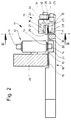
- the monitoring member 15 is laterally in the longitudinal center of the Conveyor track 11 positioned stationary. It consists of two sensors 16 and 17, on opposite sides of the trajectory the blanks 10 are positioned, namely above and below the same. One of the sensors is as a transmitter and the others trained as receivers. Between the sensors 16, 17 runs a test beam, namely a light beam that temporarily is interrupted by the blanks 10. The blanks 10 for this purpose are checked with the (edge) Area conveyed between the sensors 16, 17.
- the conveyor track 11 consists of a continuous, plate-shaped Underpass 18.
- the spread blanks 10 lie on conveying surfaces 19 and 20 of the underpass 18. In the middle runs in the conveying direction a groove-like recess 21 for the Entry of the driver 14 of the belt conveyor 12.
- the spread Blanks 10 cover the recess 21.
- the conveyor track 11 are also top guides for the blanks 10 assigned. These are effective in the edge areas of the blanks 10.
- On one side of the conveyor track 11 is an upper guide 22 arranged as a horizontal leg of the underpass 18 is formed and connected to this. Between underpass 18 and top guide 22 is created in the conveying direction Guide gap 23 for the blanks 10.
- the monitoring member 15 is in a recess 25 of the conveyor track 11 positioned, namely the underpass 18 and the upper guide 22.
- the monitoring member 15 consists of a housing 26. This is here fork-shaped, namely with an upper Leg 27 and a lower leg 28. The one to be monitored The area of the blanks 10 is between the two legs 27, 28 conveyed through.
- the upper sensor 16 lies in one downward sensor surface 29 of the upper leg 27.
- the lower sensor 17 is opposite in the area of a lower, horizontal sensor surface 30 positioned.
- the sensors 16, 17 are via lines 31 and 32 within the Housing 26 connected with a cable 33 or open into this Electric wire.
- the cable 33 emerges from the housing 26 and leads to a source for the test beam, in particular a light source, on the one hand and to an (optoelectronic) evaluation device (not shown) on the other hand.
- lines 31, 32 are preferably glass fiber strands, namely made of (real) glass. These flow into the area of the sensor surfaces 29, 30. Form the ends of the glass fiber strands (lines 31, 32) directly the sensors 16, 17, i.e. transmitter and receiver for the light beam.
- At least one of the sensors 16, 17 is positioned with respect to this on the trajectory of the blanks 10 that they are in contact over the relevant, in this case lower sensor 17 are moved away. Through this rubbing touch of the Blanks 10 with the sensor 17 is a constant, effective Cleaning the sensor 11 or keeping it free of dust and other deposits guaranteed.
- the sensor 17 Adequate, light pressing force of the blanks 10 the sensor 17 can be reached in various ways. It is sufficient if the blanks 10 are substantially below Dead weight, possibly with a slight deflection the plane of the trajectory, slide over the sensor 17. In the present embodiment this is for this purpose the lower sensor surface 30 as an increase in the area of the movement path the blanks 10 are formed. As shown, that is Sensor surface 30 compared to that specified by the underpass 18 Path of movement of the blanks 10 increased and as arched Surface trained. The sensor 17 is at the highest Location of the (arc-shaped) sensor surface 30.
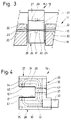
- the housing 26 consists of rigid material, especially of metal. Are inside the housing 26 Cavities formed in which the organs and lines of one Monitoring member 15 arranged and by means of investment are fixed. The monitoring member 15 is accordingly in the Cavities first with the organs and lines for the Implementation of monitoring equipped. After that, the remaining ones Open spaces with an originally flowable, hardening Mass filled, especially with synthetic resin.
- an upper chamber 34 and in the lower leg 28 a lower chamber 35 is formed.
- the chambers 34 and 35 are through an upright channel 36 in a web 37 of the U-shaped Housing 26 connected together.
- a lower one Base 38 is an outlet duct adjoining the interior 39 provided.
- holes 40, 41 which in Area of the sensor surface 29, 30 open. These holes 40, 41 serve for the passage of lines 31, 32 or for arrangement of the sensors 16, 17. runs inside the housing 26 the upper conduit 31 in the upper chamber 34 and upright Channel 36 to the outlet channel 39, namely to the cable 33.
- the lower line 32 leads from the sensor surface 30 via the Chamber 35 for cable 33.
- the housing is for filling the investment material into the cavities 26 provide covers at the top and bottom in the area of the cavities, especially with plastic or metal cover plates, which are pressed onto the investment material before curing and so be connected to this.
- the monitoring member 15 or the housing 26 is in the present Trap attached to the conveyor track 11 with a fastening element, with a fastening bolt 42, which by a laterally offset opening 43 in the web 37 of the housing 26 passes through.
- the fastening bolt 42 connects the monitoring element with an upright support leg 44 of the underpass 18th
- Blanks 10 can also have continuous webs of material, too those with print marks for controlling organs of the packaging machine, be scanned in the manner described. At least one sensor is continuously scanned by the adjacent one Material web cleaned. If the packaging material accordingly is formed, a rough side can face down or facing the sensor to be cleaned.
Landscapes
- Engineering & Computer Science (AREA)
- Mechanical Engineering (AREA)
- Wrapping Of Specific Fragile Articles (AREA)
- Investigating Materials By The Use Of Optical Means Adapted For Particular Applications (AREA)
- Photo Coupler, Interrupter, Optical-To-Optical Conversion Devices (AREA)
- Controlling Sheets Or Webs (AREA)
- Length Measuring Devices By Optical Means (AREA)
Applications Claiming Priority (2)
| Application Number | Priority Date | Filing Date | Title |
|---|---|---|---|
| DE19704718 | 1997-02-07 | ||
| DE19704718A DE19704718A1 (de) | 1997-02-07 | 1997-02-07 | Verfahren und Vorrichtung zum optoelektronischen Überwachen von Verpackungsmaterial |
Publications (2)
| Publication Number | Publication Date |
|---|---|
| EP0857652A1 true EP0857652A1 (fr) | 1998-08-12 |
| EP0857652B1 EP0857652B1 (fr) | 2003-06-11 |
Family
ID=7819633
Family Applications (1)
| Application Number | Title | Priority Date | Filing Date |
|---|---|---|---|
| EP98100254A Expired - Lifetime EP0857652B1 (fr) | 1997-02-07 | 1998-01-09 | Procédé et dispositif pour le contrôle opto-électronique de matériau d'emballage |
Country Status (7)
| Country | Link |
|---|---|
| US (1) | US6038836A (fr) |
| EP (1) | EP0857652B1 (fr) |
| JP (1) | JPH1111426A (fr) |
| CN (1) | CN1091055C (fr) |
| BR (1) | BR9800571A (fr) |
| DE (2) | DE19704718A1 (fr) |
| ES (1) | ES2201342T3 (fr) |
Families Citing this family (15)
| Publication number | Priority date | Publication date | Assignee | Title |
|---|---|---|---|---|
| DE19817824A1 (de) | 1998-04-21 | 1999-10-28 | Focke & Co | Vorrichtung zum Prüfen von Einheiten aus mehreren Einzelgegenständen, Materiallagen oder dergleichen |
| DE19827412A1 (de) * | 1998-06-19 | 1999-12-30 | Focke & Co | Verfahren und Vorrichtung zum Herstellen von Packungen |
| FI110720B (fi) * | 2001-04-09 | 2003-03-14 | Metso Paper Automation Oy | Menetelmä ja sovitelma mittalaitteen puhtaanapitämiseksi |
| US7763663B2 (en) * | 2001-12-19 | 2010-07-27 | University Of Massachusetts | Polysaccharide-containing block copolymer particles and uses thereof |
| DE10246437A1 (de) * | 2002-10-04 | 2004-04-15 | Focke Gmbh & Co. Kg | Verfahren und Vorrichtung zum Erkennen eines Aufreißstreifens an einer Materialbahn |
| DE102005059859B4 (de) * | 2005-12-15 | 2013-01-10 | Sensopart Industriesensorik Gmbh | Lichtschranke |
| JP4207066B2 (ja) | 2006-08-18 | 2009-01-14 | セイコーエプソン株式会社 | 記録装置 |
| JP4241793B2 (ja) | 2006-09-25 | 2009-03-18 | セイコーエプソン株式会社 | 媒体搬送装置 |
| DE102008014350B4 (de) * | 2008-03-14 | 2010-06-10 | Leuze Electronic Gmbh & Co Kg | Gabellichtschranke |
| FR2961742B1 (fr) * | 2010-06-29 | 2012-08-03 | Sidel Participations | Machine de formage de decoupes en carton |
| CN102595820B (zh) * | 2012-03-11 | 2014-09-17 | 郑小玲 | 一种光电感应封装机构 |
| US9562325B2 (en) * | 2013-12-27 | 2017-02-07 | Seiko Epson Corporation | Sheet manufacturing apparatus and sheet manufacturing method |
| FR3030351B1 (fr) * | 2014-12-19 | 2016-12-30 | Bobst Lyon | Dispositif et procede de controle de la qualite de boites pliables et installation de fabrication comprenant un tel dispositif de controle |
| NL2016340B1 (en) | 2016-03-01 | 2017-09-11 | Rexnord Flattop Europe Bv | Method and system for transporting products. |
| EP3589566A4 (fr) * | 2017-03-01 | 2020-12-30 | Rexnord Industries, LLC | Systèmes et procédés pour transporteur |
Citations (4)
| Publication number | Priority date | Publication date | Assignee | Title |
|---|---|---|---|---|
| GB2049926A (en) * | 1979-05-12 | 1980-12-31 | Adamovske Strojirny Np | Photoelectric device for sensing the height of a pile of paper |
| EP0142129A2 (fr) * | 1983-11-17 | 1985-05-22 | Focke & Co. (GmbH & Co.) | Dispositif de contrôle et de commande de bandes dans des machines d'emballage |
| EP0677444A1 (fr) * | 1994-04-12 | 1995-10-18 | G.D Societa' Per Azioni | Procédé de contrôle optique de produits |
| EP0791539A1 (fr) * | 1996-02-26 | 1997-08-27 | Focke & Co. (GmbH & Co.) | Procédé et dispositif pour la fabrication de boîtes à couvercle rabattant pour des cigarettes |
Family Cites Families (9)
| Publication number | Priority date | Publication date | Assignee | Title |
|---|---|---|---|---|
| US3693313A (en) * | 1970-07-29 | 1972-09-26 | Brown & Williamson Tobacco Corp | Cigarette paper tube manufacture |
| CH576242A5 (fr) * | 1974-03-13 | 1976-06-15 | Baumgartner Papiers Sa | |
| US4085928A (en) * | 1976-01-02 | 1978-04-25 | Arthur Sussman | Folding system with photoelectric detection means |
| US4486098A (en) * | 1982-02-23 | 1984-12-04 | Hauni-Werke Korber & Co. Kg | Method and apparatus for testing the ends of cigarettes or the like |
| DE3601443A1 (de) * | 1986-01-20 | 1987-07-23 | Gebhard Birkle | Vorrichtung zum fuehren und optischen abtasten von flaechigen objekten |
| IT1189918B (it) * | 1986-01-27 | 1988-02-10 | Gd Spa | Dispositivo di controllo della corretta conformazione di elementi a pacchetto |
| DE8901733U1 (de) * | 1989-02-15 | 1989-03-30 | Agfa-Gevaert Ag, 5090 Leverkusen | Vorrichtung zur Registrierung von Begußunregelmäßigkeiten |
| DE4100239A1 (de) * | 1991-01-07 | 1992-07-09 | Focke & Co | Faltvorrichtung zum herstellen von (zigaretten-)packungen |
| US5260583A (en) * | 1991-02-11 | 1993-11-09 | Rye Timothy W | Method and apparatus for detecting edge cracks |
-
1997
- 1997-02-07 DE DE19704718A patent/DE19704718A1/de not_active Withdrawn
-
1998
- 1998-01-09 DE DE59808662T patent/DE59808662D1/de not_active Expired - Lifetime
- 1998-01-09 EP EP98100254A patent/EP0857652B1/fr not_active Expired - Lifetime
- 1998-01-09 ES ES98100254T patent/ES2201342T3/es not_active Expired - Lifetime
- 1998-01-29 US US09/015,392 patent/US6038836A/en not_active Expired - Lifetime
- 1998-02-03 JP JP2234198A patent/JPH1111426A/ja active Pending
- 1998-02-06 BR BR9800571A patent/BR9800571A/pt not_active IP Right Cessation
- 1998-02-06 CN CN98104068A patent/CN1091055C/zh not_active Expired - Fee Related
Patent Citations (4)
| Publication number | Priority date | Publication date | Assignee | Title |
|---|---|---|---|---|
| GB2049926A (en) * | 1979-05-12 | 1980-12-31 | Adamovske Strojirny Np | Photoelectric device for sensing the height of a pile of paper |
| EP0142129A2 (fr) * | 1983-11-17 | 1985-05-22 | Focke & Co. (GmbH & Co.) | Dispositif de contrôle et de commande de bandes dans des machines d'emballage |
| EP0677444A1 (fr) * | 1994-04-12 | 1995-10-18 | G.D Societa' Per Azioni | Procédé de contrôle optique de produits |
| EP0791539A1 (fr) * | 1996-02-26 | 1997-08-27 | Focke & Co. (GmbH & Co.) | Procédé et dispositif pour la fabrication de boîtes à couvercle rabattant pour des cigarettes |
Also Published As
| Publication number | Publication date |
|---|---|
| JPH1111426A (ja) | 1999-01-19 |
| CN1191196A (zh) | 1998-08-26 |
| BR9800571A (pt) | 1999-06-01 |
| DE59808662D1 (de) | 2003-07-17 |
| CN1091055C (zh) | 2002-09-18 |
| DE19704718A1 (de) | 1998-08-13 |
| EP0857652B1 (fr) | 2003-06-11 |
| US6038836A (en) | 2000-03-21 |
| ES2201342T3 (es) | 2004-03-16 |
Similar Documents
| Publication | Publication Date | Title |
|---|---|---|
| EP0857652B1 (fr) | Procédé et dispositif pour le contrôle opto-électronique de matériau d'emballage | |
| EP0252871B1 (fr) | Robot industriel | |
| DE4010024B4 (de) | Fertigungsanlage mit Parallel- und Nebenförderwegen | |
| EP0615906B1 (fr) | Dispositif de contrÔle de cigarettes | |
| EP0862504A1 (fr) | Procede et dispositif pour faire passer des contenants devant un dispositif charge de controler leur fond | |
| DE3816856A1 (de) | Verfahren und vorrichtung zum pruefen von karton-packungen | |
| DE3814676A1 (de) | Montageanlage, insbesondere fuer klein- und kleinstbauteile | |
| DE3407168C2 (fr) | ||
| DE4334745C5 (de) | Vorrichtung zum Auftragen von Leim | |
| EP0816230B1 (fr) | Procédé et dispositif pour le contrôle opto-électrique d'emballages, spécialement d'emballages pour cigarettes | |
| DE3422150C2 (fr) | ||
| EP0667231A1 (fr) | Appareil pour former des flancs pour boîtes à charnière avec des arêtes longitudinales arrondies | |
| DE4010697A1 (de) | Montagestation | |
| EP0436081B1 (fr) | Dispositif de transport | |
| EP1048229B1 (fr) | Appareil et méthode pour fabriquer des cigarettes | |
| DE20114960U1 (de) | Vorrichtung zum hängenden Transport von PET-Flaschen | |
| DE20106341U1 (de) | Trenneinrichtung für eine Profilier- oder Rohrschweißanlage | |
| EP0681545A1 (fr) | Dispositif permettant de verifier des cigarettes. | |
| EP0855342A1 (fr) | Procédé et dispositif pour remplir des boítes en carton avec des articles | |
| DE19641988A1 (de) | Verpackungsmaschine mit optischen Überwachungsorganen | |
| AT403737B (de) | Messanlage für längliche gegenstände, insbesondere holzstämme | |
| EP0623533A1 (fr) | Procédé et dispositif de transport pour transporter des porte-pièces | |
| DE10227645B4 (de) | Bandfördereinrichtung | |
| DE4244965C2 (de) | Vorrichtung zum Ver- und Bearbeiten von Bauelementen sowie Biegestation | |
| DE29507908U1 (de) | Packmaschine für Gefäße |
Legal Events
| Date | Code | Title | Description |
|---|---|---|---|
| PUAI | Public reference made under article 153(3) epc to a published international application that has entered the european phase |
Free format text: ORIGINAL CODE: 0009012 |
|
| AK | Designated contracting states |
Kind code of ref document: A1 Designated state(s): CH DE ES FR GB IT LI NL |
|
| AX | Request for extension of the european patent |
Free format text: AL;LT;LV;MK;RO;SI |
|
| AKX | Designation fees paid | ||
| RBV | Designated contracting states (corrected) | ||
| RBV | Designated contracting states (corrected) |
Designated state(s): CH DE ES FR GB IT LI NL |
|
| 17P | Request for examination filed |
Effective date: 19990205 |
|
| GRAH | Despatch of communication of intention to grant a patent |
Free format text: ORIGINAL CODE: EPIDOS IGRA |
|
| GRAH | Despatch of communication of intention to grant a patent |
Free format text: ORIGINAL CODE: EPIDOS IGRA |
|
| GRAA | (expected) grant |
Free format text: ORIGINAL CODE: 0009210 |
|
| AK | Designated contracting states |
Designated state(s): CH DE ES FR GB IT LI NL |
|
| REG | Reference to a national code |
Ref country code: GB Ref legal event code: FG4D Free format text: NOT ENGLISH |
|
| REG | Reference to a national code |
Ref country code: CH Ref legal event code: EP |
|
| REG | Reference to a national code |
Ref country code: CH Ref legal event code: NV Representative=s name: PATENTBUERO PAUL ROSENICH AG |
|
| REF | Corresponds to: |
Ref document number: 59808662 Country of ref document: DE Date of ref document: 20030717 Kind code of ref document: P |
|
| GBT | Gb: translation of ep patent filed (gb section 77(6)(a)/1977) | ||
| REG | Reference to a national code |
Ref country code: ES Ref legal event code: FG2A Ref document number: 2201342 Country of ref document: ES Kind code of ref document: T3 |
|
| ET | Fr: translation filed | ||
| PLBE | No opposition filed within time limit |
Free format text: ORIGINAL CODE: 0009261 |
|
| STAA | Information on the status of an ep patent application or granted ep patent |
Free format text: STATUS: NO OPPOSITION FILED WITHIN TIME LIMIT |
|
| 26N | No opposition filed |
Effective date: 20040312 |
|
| PGFP | Annual fee paid to national office [announced via postgrant information from national office to epo] |
Ref country code: ES Payment date: 20130207 Year of fee payment: 16 Ref country code: FR Payment date: 20130204 Year of fee payment: 16 Ref country code: CH Payment date: 20130114 Year of fee payment: 16 |
|
| PGFP | Annual fee paid to national office [announced via postgrant information from national office to epo] |
Ref country code: NL Payment date: 20130110 Year of fee payment: 16 |
|
| PGFP | Annual fee paid to national office [announced via postgrant information from national office to epo] |
Ref country code: IT Payment date: 20140124 Year of fee payment: 17 |
|
| PGFP | Annual fee paid to national office [announced via postgrant information from national office to epo] |
Ref country code: GB Payment date: 20140115 Year of fee payment: 17 |
|
| REG | Reference to a national code |
Ref country code: NL Ref legal event code: V1 Effective date: 20140801 |
|
| REG | Reference to a national code |
Ref country code: CH Ref legal event code: PL |
|
| PG25 | Lapsed in a contracting state [announced via postgrant information from national office to epo] |
Ref country code: LI Free format text: LAPSE BECAUSE OF NON-PAYMENT OF DUE FEES Effective date: 20140131 Ref country code: NL Free format text: LAPSE BECAUSE OF NON-PAYMENT OF DUE FEES Effective date: 20140801 Ref country code: CH Free format text: LAPSE BECAUSE OF NON-PAYMENT OF DUE FEES Effective date: 20140131 |
|
| REG | Reference to a national code |
Ref country code: FR Ref legal event code: ST Effective date: 20140930 |
|
| PG25 | Lapsed in a contracting state [announced via postgrant information from national office to epo] |
Ref country code: FR Free format text: LAPSE BECAUSE OF NON-PAYMENT OF DUE FEES Effective date: 20140131 |
|
| REG | Reference to a national code |
Ref country code: ES Ref legal event code: FD2A Effective date: 20150407 |
|
| PG25 | Lapsed in a contracting state [announced via postgrant information from national office to epo] |
Ref country code: ES Free format text: LAPSE BECAUSE OF NON-PAYMENT OF DUE FEES Effective date: 20140110 |
|
| PGFP | Annual fee paid to national office [announced via postgrant information from national office to epo] |
Ref country code: DE Payment date: 20150129 Year of fee payment: 18 |
|
| GBPC | Gb: european patent ceased through non-payment of renewal fee |
Effective date: 20150109 |
|
| PG25 | Lapsed in a contracting state [announced via postgrant information from national office to epo] |
Ref country code: GB Free format text: LAPSE BECAUSE OF NON-PAYMENT OF DUE FEES Effective date: 20150109 |
|
| PG25 | Lapsed in a contracting state [announced via postgrant information from national office to epo] |
Ref country code: IT Free format text: LAPSE BECAUSE OF NON-PAYMENT OF DUE FEES Effective date: 20150109 |
|
| REG | Reference to a national code |
Ref country code: DE Ref legal event code: R119 Ref document number: 59808662 Country of ref document: DE |
|
| PG25 | Lapsed in a contracting state [announced via postgrant information from national office to epo] |
Ref country code: DE Free format text: LAPSE BECAUSE OF NON-PAYMENT OF DUE FEES Effective date: 20160802 |