EP0857675B1 - Blattendetektor - Google Patents
Blattendetektor Download PDFInfo
- Publication number
- EP0857675B1 EP0857675B1 EP98100890A EP98100890A EP0857675B1 EP 0857675 B1 EP0857675 B1 EP 0857675B1 EP 98100890 A EP98100890 A EP 98100890A EP 98100890 A EP98100890 A EP 98100890A EP 0857675 B1 EP0857675 B1 EP 0857675B1
- Authority
- EP
- European Patent Office
- Prior art keywords
- sheet
- end detecting
- sheet end
- supporting plate
- detecting device
- Prior art date
- Legal status (The legal status is an assumption and is not a legal conclusion. Google has not performed a legal analysis and makes no representation as to the accuracy of the status listed.)
- Expired - Lifetime
Links
- 230000000994 depressogenic effect Effects 0.000 claims description 7
- 210000000078 claw Anatomy 0.000 claims description 3
- 238000001514 detection method Methods 0.000 description 3
- 238000000034 method Methods 0.000 description 2
- 238000005452 bending Methods 0.000 description 1
- 239000011347 resin Substances 0.000 description 1
- 229920005989 resin Polymers 0.000 description 1
Images

Classifications
-
- G—PHYSICS
- G03—PHOTOGRAPHY; CINEMATOGRAPHY; ANALOGOUS TECHNIQUES USING WAVES OTHER THAN OPTICAL WAVES; ELECTROGRAPHY; HOLOGRAPHY
- G03G—ELECTROGRAPHY; ELECTROPHOTOGRAPHY; MAGNETOGRAPHY
- G03G15/00—Apparatus for electrographic processes using a charge pattern
- G03G15/65—Apparatus which relate to the handling of copy material
-
- B—PERFORMING OPERATIONS; TRANSPORTING
- B65—CONVEYING; PACKING; STORING; HANDLING THIN OR FILAMENTARY MATERIAL
- B65H—HANDLING THIN OR FILAMENTARY MATERIAL, e.g. SHEETS, WEBS, CABLES
- B65H7/00—Controlling article feeding, separating, pile-advancing, or associated apparatus, to take account of incorrect feeding, absence of articles, or presence of faulty articles
- B65H7/02—Controlling article feeding, separating, pile-advancing, or associated apparatus, to take account of incorrect feeding, absence of articles, or presence of faulty articles by feelers or detectors
-
- B—PERFORMING OPERATIONS; TRANSPORTING
- B65—CONVEYING; PACKING; STORING; HANDLING THIN OR FILAMENTARY MATERIAL
- B65H—HANDLING THIN OR FILAMENTARY MATERIAL, e.g. SHEETS, WEBS, CABLES
- B65H2511/00—Dimensions; Position; Numbers; Identification; Occurrences
- B65H2511/20—Location in space
-
- B—PERFORMING OPERATIONS; TRANSPORTING
- B65—CONVEYING; PACKING; STORING; HANDLING THIN OR FILAMENTARY MATERIAL
- B65H—HANDLING THIN OR FILAMENTARY MATERIAL, e.g. SHEETS, WEBS, CABLES
- B65H2511/00—Dimensions; Position; Numbers; Identification; Occurrences
- B65H2511/50—Occurence
- B65H2511/51—Presence
- B65H2511/514—Particular portion of element
-
- B—PERFORMING OPERATIONS; TRANSPORTING
- B65—CONVEYING; PACKING; STORING; HANDLING THIN OR FILAMENTARY MATERIAL
- B65H—HANDLING THIN OR FILAMENTARY MATERIAL, e.g. SHEETS, WEBS, CABLES
- B65H2553/00—Sensing or detecting means
- B65H2553/60—Details of intermediate means between the sensing means and the element to be sensed
- B65H2553/61—Mechanical means, e.g. contact arms
-
- B—PERFORMING OPERATIONS; TRANSPORTING
- B65—CONVEYING; PACKING; STORING; HANDLING THIN OR FILAMENTARY MATERIAL
- B65H—HANDLING THIN OR FILAMENTARY MATERIAL, e.g. SHEETS, WEBS, CABLES
- B65H2701/00—Handled material; Storage means
- B65H2701/10—Handled articles or webs
- B65H2701/13—Parts concerned of the handled material
- B65H2701/131—Edges
- B65H2701/1311—Edges leading edge
-
- B—PERFORMING OPERATIONS; TRANSPORTING
- B65—CONVEYING; PACKING; STORING; HANDLING THIN OR FILAMENTARY MATERIAL
- B65H—HANDLING THIN OR FILAMENTARY MATERIAL, e.g. SHEETS, WEBS, CABLES
- B65H2701/00—Handled material; Storage means
- B65H2701/10—Handled articles or webs
- B65H2701/13—Parts concerned of the handled material
- B65H2701/131—Edges
- B65H2701/1313—Edges trailing edge
-
- G—PHYSICS
- G03—PHOTOGRAPHY; CINEMATOGRAPHY; ANALOGOUS TECHNIQUES USING WAVES OTHER THAN OPTICAL WAVES; ELECTROGRAPHY; HOLOGRAPHY
- G03G—ELECTROGRAPHY; ELECTROPHOTOGRAPHY; MAGNETOGRAPHY
- G03G2215/00—Apparatus for electrophotographic processes
- G03G2215/00362—Apparatus for electrophotographic processes relating to the copy medium handling
- G03G2215/00535—Stable handling of copy medium
- G03G2215/00717—Detection of physical properties
- G03G2215/00721—Detection of physical properties of sheet position
Definitions
- the present invention relates to a sheet end detecting device. More particular, the present invention is directed to a sheet end detecting device which is disposed in a sheet conveyance path of a device such as a printer, a photocopier, or the like.
- a sheet end detecting sensor which is disposed in a part of a sheet conveyance path and which is utilized in a printer, a photocopier, or the like, for detection of a front end and a rear end of a sheet and output thereof, generally has a structure wherein a tip of a detection lever is attached to a member in the vicinity of a sheet conveyance roller so as to protrude from a sheet guide plate.
- a sensor is disclosed in GB 2 004 843.
- the object of the present invention is to provide a new sheet end detecting device which can be simply attached to a device, such as a printer, during the final step of assembling operations.
- Another object of the present invention is to provide a sheet end detecting device which can be positioned easily and accurately, so as to be secured against a sheet conveyance roller.
- a depressed part that bears a sheet conveyance roller shaft and a pair of leg pieces that elastically engage with both lateral side edges of an attachment hole on a sheet guide plate are provided on one side of a supporting plate that sustains a sheet end detecting element, while the other side of the supporting plate is in contact with a rear surface of the sheet guide plate in a state wherein the attachment hole is engaged with the leg pieces.
- the depressed bearing part which is provided in the supporting plate is turned over while being fitted with the sheet conveyance roller shaft and the pair of leg pieces which protrude from the supporting plate are engaged with the attachment hole so that the sheet end detecting device is accurately positioned on and supported by the sheet conveyance roller shaft.
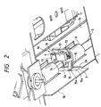
- Figure 1 shows a printer which comprises a sheet end detecting sensor viewed on the sheet exit side of the printer and Figure 2 shows a view on the rear side.
- a sheet guide plate 1 has a horizontal part 1a which extends toward the sheet exit side and is bent downward at an end part thereof to form a vertical part 1b.
- the bent part of the guide plate 1 is provided with an array of a plurality of window holes 2 in a widthwise direction, through which each of rollers 6 that are secured on a common sheet discharge roller shaft 5 is disposed so as to expose a circumferential part thereof from a rear side of the sheet guide plate 1, and a unit attachment hole 3, which is slightly wider than a sheet end detector unit 10 described below, is formed by stamping between the above-described window holes 2.
- the sheet end detector unit 10 which is attached to the sheet discharge roller shaft 5 through the unit attachment hole 3 comprises a detecting lever 11 which is provided so as to protrude a tip thereof from the sheet guide plate 1 and which is supported so as to swing freely, a limit switch 12 which outputs a sheet end detecting signal based on actions of the detecting lever 11 and a supporting plate 13 which supports these components.
- the supporting plate 13 is formed of an elastic resin. On one side of the supporting plate 13, a semicircular depressed attachment part 14 for elastic bearing of the sheet discharge roller shaft 5 is formed. On the same side as the depressed attachment part 14, two leg pieces 15 which each have an engagement claw 15a at the tips, protrude and stretch apart so as to make elastic engagement with both lateral side edges 3a of the unit attachment hole 3 (see Fig. 2).
- the other side of the supporting plate 13 has a lateral side edge 16 which is in contact with a rear surface of the horizontal part 1a of the sheet guide plate 1 when the two leg pieces 15 are being engaged with the lateral side edges 3a of the unit attachment hole 3.
- the lateral side edge 16 is stopped by and secured to the rear surface of the sheet guide plate 1 after being turned over from the front surface side, using the sheet discharge roller shaft 5 as a fulcrum.
- This part of the sheet guide plate 1 which abuts the side edge 16 is bent inward to form a pair of holder pieces 4 so that the lateral side edge 16 of the supporting plate 13 is held between both holder pieces 4.
- a sheet feed roller 7, an impact type recording head 8 and a carriage guide 9 are also shown in the drawings.
- the sheet end detector unit 10 is inserted to the rear side of the sheet guide plate 1 through the unit attachment hole 3 in the sheet guide plate 1 while the tip of the detecting lever 11 is directed upward, and the supporting plate 13 is attached to the sheet discharge roller shaft 5 so that the depressed attachment part 14 is fitted on the sheet discharge roller shaft 5 from below.
- the two leg pieces 15 that protrude from one side of the supporting plate 13 are squeezed to enter the unit attachment hole 3 at a position close to the end of the rotation and are locked by the engagement claws 15a engaging with the lateral side edges 3a.
- the lateral side edge 16 of the supporting plate 13 which comes into contact with the rear surface of the horizontal part 1a of the sheet guide plate 1 is held between the holder pieces 4 which are formed at both sides thereof by bending, as shown in Figure 2, to be attached to the sheet discharge roller shaft 5.
- this sheet end detector unit 10 can be attached readily to a completely assembled printer without the use of screws. In addition, the sheet end detector unit 10 can be removed simply by reversing the attachment procedures. Moreover, since the sheet discharge roller shaft 5 is utilized as a datum for positioning, the front end and rear end of the recording sheet can be detected with an extreme accuracy.
- the present invention has been exemplified with an embodiment wherein the sheet end detector unit is disposed on the sheet exit side, it should be clearly understood that this may be disposed on the sheet entrance side.
- the depressed part that bears the sheet conveyance roller shaft and the pair of leg pieces that engage with the attachment hole on the sheet guide plate are provided on one side of the supporting plate that sustains the sheet end detecting element, while the other side of the supporting plate is in contact with the rear surface of the sheet guide plate in the state wherein the attachment hole is engaged with the leg pieces.
- the present invention realizes not only the simple assembling operation of the sheet end detecting device into a part of the sheet transporting path without the use of attachment screws, but also the simple removing operation by reversing these operations. Furthermore, positioning of the sheet detection unit with the sheet conveyance roller shaft as the datum thereof greatly enhances the detecting accuracy of the front end or the rear end of the sheet.
Landscapes
- Physics & Mathematics (AREA)
- General Physics & Mathematics (AREA)
- Controlling Sheets Or Webs (AREA)
Claims (5)
- Blattenden-Erfassungseinrichtung mit:einem Blattenden-Erfassungselement (11),einer Halteplatte (13) zum Halten des Blattenden-Erfassungselements (11),einem niedergedrückten Bereich (14) an einer Seite der Halteplatte (13) zum Lagern gegen eine Welle (5) von Blattförderrollen,einem Paar von Beinelementen (15) an der einen Seite der Halteplatte (13) für einen elastischen Eingriff mit beiden seitlichen Seitenkanten (3a) einer Anbringöffnung (3) an einer Blattführungsplatte (1a), undeinem Kontaktbereich (16) an einer anderen Seite der Halteplatte (13),wobei der Kontaktbereich (16) eine rückwärtige Fläche der Blattführungsplatte (1a) kontaktiert, wenn die Anbringöffnung (3) und die Beinelemente (15) in einem Eingriffszustand sind.
- Blattenden-Erfassungseinrichtung nach Anspruch 1, wobei die Blattführungsplatte (1) eine Blattförderfläche (1a) sowie eine Wandfläche (1b) aufweist, welche in näherungsweise einem rechten Winkel zu der Blattförderfläche (1a) angeordnet ist, und wobei die Anbringöffnung (3) in der Wandfläche (1b) angeordnet ist.
- Blattenden-Erfassungseinrichtung nach Anspruch 1, wobei die Beinelemente (15) jeweils eine Eingriffsklaue (15a) haben, die an einem Endbereich des jeweiligen Beinelements ausgebildet ist.
- Blattenden-Erfassungseinrichtung nach Anspruch 1, wobei die rückwärtige Fläche der Blattführungsplatte (1a) ein Paar von nach innen gebogenen Stücken (4) zum Anstoßen gegen den Kontaktbereich (16) der Kontaktplatte (13) aufweist.
- Blattenden-Erfassungseinrichtung nach Anspruch 1, weiter mit einem Grenzschalter (12) zum Ausgeben eines Blattenden-Erfassungssignals gemäß einer Aktion des Blattenden-Erfassungselements (11).
Applications Claiming Priority (3)
| Application Number | Priority Date | Filing Date | Title |
|---|---|---|---|
| JP02105797A JP3379566B2 (ja) | 1997-01-20 | 1997-01-20 | 紙端検出装置 |
| JP21057/97 | 1997-01-20 | ||
| JP2105797 | 1997-01-20 |
Publications (3)
| Publication Number | Publication Date |
|---|---|
| EP0857675A2 EP0857675A2 (de) | 1998-08-12 |
| EP0857675A3 EP0857675A3 (de) | 1999-03-03 |
| EP0857675B1 true EP0857675B1 (de) | 2001-11-07 |
Family
ID=12044287
Family Applications (1)
| Application Number | Title | Priority Date | Filing Date |
|---|---|---|---|
| EP98100890A Expired - Lifetime EP0857675B1 (de) | 1997-01-20 | 1998-01-20 | Blattendetektor |
Country Status (4)
| Country | Link |
|---|---|
| US (1) | US5941523A (de) |
| EP (1) | EP0857675B1 (de) |
| JP (1) | JP3379566B2 (de) |
| DE (1) | DE69802314T2 (de) |
Families Citing this family (1)
| Publication number | Priority date | Publication date | Assignee | Title |
|---|---|---|---|---|
| JP4193069B2 (ja) * | 2005-08-31 | 2008-12-10 | ブラザー工業株式会社 | 給紙装置及びそれを備えた画像記録装置 |
Family Cites Families (4)
| Publication number | Priority date | Publication date | Assignee | Title |
|---|---|---|---|---|
| DE2739653A1 (de) * | 1977-09-02 | 1979-03-08 | Agfa Gevaert Ag | Papierfuehlersteuerung |
| JPS6392553A (ja) * | 1986-10-03 | 1988-04-23 | Ricoh Co Ltd | 複写機等の紙搬送制御方法 |
| DE3837250C1 (de) * | 1988-10-31 | 1990-03-15 | Mannesmann Ag, 4000 Duesseldorf, De | |
| JP3102914B2 (ja) * | 1991-07-16 | 2000-10-23 | キヤノン株式会社 | スイッチング式直流電源装置 |
-
1997
- 1997-01-20 JP JP02105797A patent/JP3379566B2/ja not_active Expired - Fee Related
-
1998
- 1998-01-20 EP EP98100890A patent/EP0857675B1/de not_active Expired - Lifetime
- 1998-01-20 DE DE69802314T patent/DE69802314T2/de not_active Expired - Fee Related
- 1998-01-20 US US09/009,687 patent/US5941523A/en not_active Expired - Lifetime
Also Published As
| Publication number | Publication date |
|---|---|
| US5941523A (en) | 1999-08-24 |
| JP3379566B2 (ja) | 2003-02-24 |
| EP0857675A2 (de) | 1998-08-12 |
| JPH10203684A (ja) | 1998-08-04 |
| DE69802314D1 (de) | 2001-12-13 |
| EP0857675A3 (de) | 1999-03-03 |
| DE69802314T2 (de) | 2002-07-11 |
Similar Documents
| Publication | Publication Date | Title |
|---|---|---|
| US5820068A (en) | Printer with paper end detection | |
| US20130010315A1 (en) | Printer capable of preventing paper jam | |
| US5941523A (en) | Sheet end detecting device | |
| EP1591241B1 (de) | Bildaufzeichnungsgerät | |
| US5486061A (en) | Paper feeding method and apparatus for preventing the double feeding of papers | |
| US20090174139A1 (en) | Label sheet out-feeding detection device for barcode printer | |
| JP2503252B2 (ja) | 光学式媒体検出装置 | |
| JP3724641B2 (ja) | 媒体搬送装置 | |
| US6073928A (en) | Sheet end detecting mechanism | |
| JPH11130310A (ja) | ロール紙検出装置 | |
| JP3076939B2 (ja) | 車載プリンタのセンサレバー機構 | |
| US5110025A (en) | Paper feeder having a paper exhaustion detector | |
| JP2020019233A (ja) | 記録装置および記録方法 | |
| JP3174376B2 (ja) | シ−ト検知装置 | |
| JP2002347995A (ja) | シート供給装置及び処理装置 | |
| JP2000163624A (ja) | 紙葉類識別装置 | |
| JPH08169633A (ja) | 用紙ジャム検出機構 | |
| JPH09301570A (ja) | 媒体搬送装置 | |
| US6074114A (en) | Color printer for repetitively printing a document | |
| JPH02791B2 (de) | ||
| JPS5943321Y2 (ja) | 紙葉類処理機におけるマイクロスイツチ支持装置 | |
| JPH0314374Y2 (de) | ||
| KR890006197Y1 (ko) | 레이저 프린터의 수차 급지장치 | |
| JP2017013945A (ja) | 媒体幅検出装置及び画像形成装置 | |
| KR0121535Y1 (ko) | 프린터 헤드 위치 감지장치 |
Legal Events
| Date | Code | Title | Description |
|---|---|---|---|
| PUAI | Public reference made under article 153(3) epc to a published international application that has entered the european phase |
Free format text: ORIGINAL CODE: 0009012 |
|
| AK | Designated contracting states |
Kind code of ref document: A2 Designated state(s): DE FR GB |
|
| AX | Request for extension of the european patent |
Free format text: AL;LT;LV;MK;RO;SI |
|
| PUAL | Search report despatched |
Free format text: ORIGINAL CODE: 0009013 |
|
| AK | Designated contracting states |
Kind code of ref document: A3 Designated state(s): AT BE CH DE DK ES FI FR GB GR IE IT LI LU MC NL PT SE |
|
| AX | Request for extension of the european patent |
Free format text: AL;LT;LV;MK;RO;SI |
|
| 17P | Request for examination filed |
Effective date: 19990315 |
|
| AKX | Designation fees paid |
Free format text: DE FR GB |
|
| GRAG | Despatch of communication of intention to grant |
Free format text: ORIGINAL CODE: EPIDOS AGRA |
|
| 17Q | First examination report despatched |
Effective date: 20001207 |
|
| GRAG | Despatch of communication of intention to grant |
Free format text: ORIGINAL CODE: EPIDOS AGRA |
|
| GRAH | Despatch of communication of intention to grant a patent |
Free format text: ORIGINAL CODE: EPIDOS IGRA |
|
| GRAH | Despatch of communication of intention to grant a patent |
Free format text: ORIGINAL CODE: EPIDOS IGRA |
|
| GRAA | (expected) grant |
Free format text: ORIGINAL CODE: 0009210 |
|
| AK | Designated contracting states |
Kind code of ref document: B1 Designated state(s): DE FR GB |
|
| REF | Corresponds to: |
Ref document number: 69802314 Country of ref document: DE Date of ref document: 20011213 |
|
| REG | Reference to a national code |
Ref country code: GB Ref legal event code: IF02 |
|
| PLBE | No opposition filed within time limit |
Free format text: ORIGINAL CODE: 0009261 |
|
| STAA | Information on the status of an ep patent application or granted ep patent |
Free format text: STATUS: NO OPPOSITION FILED WITHIN TIME LIMIT |
|
| 26N | No opposition filed | ||
| PGFP | Annual fee paid to national office [announced via postgrant information from national office to epo] |
Ref country code: GB Payment date: 20080116 Year of fee payment: 11 Ref country code: DE Payment date: 20080117 Year of fee payment: 11 |
|
| PGFP | Annual fee paid to national office [announced via postgrant information from national office to epo] |
Ref country code: FR Payment date: 20080108 Year of fee payment: 11 |
|
| GBPC | Gb: european patent ceased through non-payment of renewal fee |
Effective date: 20090120 |
|
| PG25 | Lapsed in a contracting state [announced via postgrant information from national office to epo] |
Ref country code: DE Free format text: LAPSE BECAUSE OF NON-PAYMENT OF DUE FEES Effective date: 20090801 |
|
| REG | Reference to a national code |
Ref country code: FR Ref legal event code: ST Effective date: 20091030 |
|
| PG25 | Lapsed in a contracting state [announced via postgrant information from national office to epo] |
Ref country code: GB Free format text: LAPSE BECAUSE OF NON-PAYMENT OF DUE FEES Effective date: 20090120 |
|
| PG25 | Lapsed in a contracting state [announced via postgrant information from national office to epo] |
Ref country code: FR Free format text: LAPSE BECAUSE OF NON-PAYMENT OF DUE FEES Effective date: 20090202 |