EP0857839A2 - Randanordnung - Google Patents
Randanordnung Download PDFInfo
- Publication number
- EP0857839A2 EP0857839A2 EP98300160A EP98300160A EP0857839A2 EP 0857839 A2 EP0857839 A2 EP 0857839A2 EP 98300160 A EP98300160 A EP 98300160A EP 98300160 A EP98300160 A EP 98300160A EP 0857839 A2 EP0857839 A2 EP 0857839A2
- Authority
- EP
- European Patent Office
- Prior art keywords
- mat
- edging
- strip
- edge
- edges
- Prior art date
- Legal status (The legal status is an assumption and is not a legal conclusion. Google has not performed a legal analysis and makes no representation as to the accuracy of the status listed.)
- Withdrawn
Links
- 238000007688 edging Methods 0.000 title claims abstract description 87
- 230000000295 complement effect Effects 0.000 claims description 27
- 239000000463 material Substances 0.000 claims description 3
- 229920003023 plastic Polymers 0.000 claims description 3
- 239000004033 plastic Substances 0.000 claims description 3
- 238000001125 extrusion Methods 0.000 claims description 2
- 230000000712 assembly Effects 0.000 description 2
- 238000000429 assembly Methods 0.000 description 2
- 230000000149 penetrating effect Effects 0.000 description 2
- 238000007790 scraping Methods 0.000 description 2
- 238000000926 separation method Methods 0.000 description 2
- 235000001674 Agaricus brunnescens Nutrition 0.000 description 1
- 241001423398 Ruscus hypoglossum Species 0.000 description 1
- 238000003491 array Methods 0.000 description 1
- 239000013536 elastomeric material Substances 0.000 description 1
- 238000012986 modification Methods 0.000 description 1
- 230000004048 modification Effects 0.000 description 1
- 230000000284 resting effect Effects 0.000 description 1
- 210000002105 tongue Anatomy 0.000 description 1
Images

Classifications
-
- E—FIXED CONSTRUCTIONS
- E04—BUILDING
- E04F—FINISHING WORK ON BUILDINGS, e.g. STAIRS, FLOORS
- E04F15/00—Flooring
- E04F15/02—Flooring or floor layers composed of a number of similar elements
- E04F15/10—Flooring or floor layers composed of a number of similar elements of other materials, e.g. fibrous or chipped materials, organic plastics, magnesite tiles, hardboard, or with a top layer of other materials
-
- A—HUMAN NECESSITIES
- A47—FURNITURE; DOMESTIC ARTICLES OR APPLIANCES; COFFEE MILLS; SPICE MILLS; SUCTION CLEANERS IN GENERAL
- A47L—DOMESTIC WASHING OR CLEANING; SUCTION CLEANERS IN GENERAL
- A47L23/00—Cleaning footwear
- A47L23/22—Devices or implements resting on the floor for removing mud, dirt, or dust from footwear
- A47L23/24—Rigid cleaning-gratings; Tread plates or scrapers for cleaning the soles of footwear
-
- E—FIXED CONSTRUCTIONS
- E04—BUILDING
- E04F—FINISHING WORK ON BUILDINGS, e.g. STAIRS, FLOORS
- E04F15/00—Flooring
- E04F15/02—Flooring or floor layers composed of a number of similar elements
- E04F15/02194—Flooring consisting of a number of elements carried by a non-rollable common support plate or grid
-
- E—FIXED CONSTRUCTIONS
- E04—BUILDING
- E04F—FINISHING WORK ON BUILDINGS, e.g. STAIRS, FLOORS
- E04F15/00—Flooring
- E04F15/02—Flooring or floor layers composed of a number of similar elements
- E04F15/08—Flooring or floor layers composed of a number of similar elements only of stone or stone-like material, e.g. ceramics, concrete; of glass or with a top layer of stone or stone-like material, e.g. ceramics, concrete or glass
- E04F15/082—Flooring or floor layers composed of a number of similar elements only of stone or stone-like material, e.g. ceramics, concrete; of glass or with a top layer of stone or stone-like material, e.g. ceramics, concrete or glass with a top layer of stone or stone-like material, e.g. ceramics, concrete or glass in combination with a lower layer of other material
Definitions
- This invention relates to an edging system, and relates more particularly but not exclusively to an edging system by which edging strips can be applied to a floor mat or the like, and to floor mats (or the like) edged thereby.
- scraper mats may also be employed for reducing levels of mud carried on footwear in locations such as building sites and farms. It is known for scraper mats to be formed of mutually interlocking tiles such that mats in a wide range of lengths and breadths can be assembled from an appropriate number of identical tiles. However, mats assembled from tiles which mutually interlock along their edges leave the outer edges of the assembled mats unfinished in terms of lacking a distinct boundary strip, and also presenting raised and frequently step-like edges which represent a trip hazard for mats which are not adequately recessed in a mat-holding well.
- an edging system for a mat or the like having edges adapted for attachment to complementary edges, the edging system comprising adaptor means attachable to selected parts of the mat edges to be self-securing to the mat edge and to present edging attachment means adjacent the mat edge, the edging system further comprising edging strip means attachable to the edging attachment means to form an edge extending along one or more selected sides of the mat.
- the edging strip means may comprise a strip of plastics material which may be of indeterminate length and may be formed by extrusion, the strip preferably being integrally formed with strip attachment means complementary to the edging attachment means of the adaptor means for mutual attachment to the respective attachment means in an assembled edging system.
- the edging attachment means of the adaptor means may comprise one or more projections, or an extended ridge-like projection, having a barb-like cross-section, the strip attachment means of the edging strip means comprising one or a plurality of apertures, or an extended groove, having re-entrant edges for hooking onto the barb-like cross-section of the projection or projections of the edging attachment means.
- the edging strip means preferably has a thickness which diminishes from an edge adjacent the mat in an assembled edging system, to the opposite edge which will be the outer edge of the combined mat plus assembled edging system whereby the edging system forms a tapered or chamfered edge to the mat along the one or more selected sides of the mat.
- the adaptor means may comprise a strip-like article, preferably having a length about equal to the length of a side of the mat or about equal to the length of a sub-unit of the mat (eg of an individual tile from which the mat is assembled), the adaptor means having a complementary edge formed along at least one side thereof, the complementary edge being compatible with or substantially identical to the complementary edge to which the edge of the mat is adapted for attachment.
- the edging system may additionally comprise corner means attachable to one or more selected corners of an edging system assembled on the mat, the corner means being adapted to provide continuity between edging strip means extending along adjacent sides of the mat.
- the corner means preferably comprises a respective corner unit which is substantially L-shaped in plan and having a cross-section which preferably substantially matches the cross-section of the edging strip means.
- an edged mat comprising an assembly of a mat and an edging system, the mat having edges adapted for attachment to complementary edges, the edging system being an edging system according to the first aspect of the present invention and assembled with the mat to form an edged mat having an edge extending along one or more selected sides of the mat.
- the mat is (prior to assembly) preferably a sub-assembly of a plurality of tiles adapted by the provision of complementary edges on each said tile to be mutually interlocking along their respective adjacent edges and to leave initially unconnected outer edges as mat edges adapted for attachment to complementary edges whereby to be attachable to further such tiles or to be attachable to the edging system to form the assembly.
- the complementary edges are preferably formed to produce half-lap joints in the assembled mat, and mutual interlocking of these joints may be enabled or enhanced by the provision of mutually interpenetrating plug and socket connector arrays along respective ones of adjacent pairs of the complementary edges.
- the mat is preferably adapted for the scraping and/or wiping of footwear worn by persons walking upon the mat.
- kits of parts for forming an edging system for a mat or the like having edges adapted for attachment to complementary edges comprising a plurality of adaptor means attachable to selected parts of the mat edges to be self-securing to the mat edge and to present edging attachment means adjacent the mat edge, the kit further comprising an indeterminate length of edging strip means attachable to the edging attachment means of the adaptor means.
- the kit may additionally comprise a plurality of corner means attachable to selected corners of a mat and/or attachable to selected corners of an edging system assembled on a mat from parts provided by the kit.
- kit of parts for forming assemblies each comprising an assembly of a mat and an edging system
- the kit of parts comprising a kit of parts according to the third aspect of the present invention and further comprising a plurality of tiles adapted by the provision of complementary edges on each said tile to be mutually interlocking along their respective adjacent edges and to leave initially unconnected outer edges as mat edges for attachment to further such tiles or to the adaptor means.
- the mat to which the edging system of the invention is applied is a scraper mat formed by an assembly of proprietary mat tiles available from the company named Muovihaka OY, of Finland. These mat tiles are substantially square with sides of the order of 20 centimetres, and are formed to be mutually interlocking along their edges to form half-lap joints between adjacent tiles. In each such tile, two adjacent edges are each formed with a row of laterally projecting sockets which are vertically open from above, and whose full height is confined to the vertically lower half of the thickness of the tile.
- each such tile is each formed with a row of downwardly projecting mushroom-headed pegs, each of these pegs being rooted in a laterally projecting part of the respective tile edge which is confined to the vertically upper half of the thickness of the tile.
- the pegs project downwardly through the vertically lower half of the vertical height of the tile.
- the body of each such mat tile ie the bulk of the mat tile between and bounded by the above-described interlocking edges, is moulded of an elastomeric material in an open lattice form, with upwardly directed bristle-like projections, such that mats assembled by interlocking a suitable number of tiles can function as scraper mats for the wiping of excessive dirt from footwear of persons walking over such mats.
- each mat tile has two kinds of edge, namely “socket edges” and “peg edges", these two kinds of edge being mutually complementary edges.
- Tiles can be interconnected by bringing complementary types of edge into mutually overlapping engagement, and then pressing the overlapping edges together such that the pegs on the edge of one tile enter the sockets in the complementary edge of the other tile, where the mushroom heads latch the pegs into respective sockets and so lock the two tiles together along their adjacent edges.
- Mats of a desired size can be built up by interconnecting suitable numbers of tiles, and the outer edges of the resultant mat will always present one or other (or both) of these complimentary tile edges, thus to be available for the connection of further tiles (as mat extensions) or for the connection of an edging system as a solution to the problem now to be described.
- Scraper mats formed by assemblies of tiles interlocked as described above may be used on floors, on paved surfaces, or on unpaved ground.
- the substantial thickness of the mat normally stands above the usual surface on which mat users walk.
- these mats are liable to be a trip hazard.
- the unfinished edges of the mat present an unaesthetic appearance.
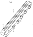
- FIG. 1 this illustrates an adaptor strip 10 designed to fit on to a "peg edge" of a mat (not shown in Fig. 1).
- the strip 10 is formed along the vertically lower half of one edge (the nearer edge as viewed in Fig. 1) with a row of vertically open sockets 12 which are functionally equivalent to the "socket edge” of a further tile and thus complementary to the "peg edge” of the mat to which the adaptor strip 10 will be attached in use (as shown in Fig. 4A).
- the adaptor strip 10 is shown in Fig. 1 as having only two sockets 12, at opposite ends of the strip 10, such that the illustrated adaptor strip is a minimum practicable length. However, it is preferred that the adaptor strip 10 have a length about that of the edge of a standard mat tile (which has six equi-spaced sockets in the specific case previously referred to).
- the full length of the strip 10 is formed with an upstanding ridge 14 having a barb-like cross-section (for a purpose detailed hereafter).
- the ridge 14 is horizontally displaced from the centre-line of the row of sockets 12.
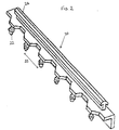
- FIG. 2 this illustrates an adaptor strip 20 designed to fit on to a "socket edge" of a mat (not shown in Fig. 2).
- the strip 20 is formed along the vertically lower half of one edge (the nearer edge as viewed in Fig. 2) with a row of vertically depending mushroom-headed pegs 22 which are functionally equivalent to the "peg edge” of a further tile and thus complementary to the "socket edge" of the mat to which the adaptor strip 20 will be attached in use (as shown in Fig. 4B).
- Each of the downwardly directed pegs 22 is rooted in a part of the body of the strip 20 which is in the vertically upper half of the strip 20.
- the adaptor strip 20 as shown in Fig. 2 is a short two-peg length strip, but is preferably the six-peg length of a full tile side.
- the adaptor strip 20 Whatever the length of the adaptor strip 20, it is formed along its full length with an upstanding ridge 24 having a barb-like cross-section which is substantially identical to the cross-section of the ridge 14 in the adaptor strip 10.
- the ridge 14 is horizontally displaced from the centre-line of the row of pegs 22.
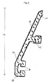
- FIG. 3 illustrates a vertical transverse cross-section of an edging strip 30 of a form suitable for use in the edging system of the present invention.
- the strip 30 has an indefinite length and its cross-section is invariant along its length.
- the strip 30 is cut to length according to requirement.
- the strip 30 is conveniently formed by extruding a plastics material, eg PVC, which is preferably self-coloured.
- the strip 30 is aligned as it will be in use (see Figs. 4A and 4B).
- the left edge 32 of the strip 30 (as viewed in Fig. 7) is formed on its underside with a downwardly open groove 34 having re-entrant edges 36 adapted to interlock with the barbs of the ridges 14 and 24 in the adaptor strips 10 and 20, as will subsequently be detailed.
- the strip 30 has an outer surface 38 which has a height that tapers from a height on its left edge 36 which is about equal to the full vertical thickness of a mat, down to essentially zero height at its right edge 40.
- the horizontal width of the strip 30 between its left edge 32 and its right edge 40 is greater than the maximum height of the strip 30, such that the surface 38 is shallowly tapered and thereby provides a chamfered edge to the assembled mat plus edging system, as will be seen from Figs. 4A and 4B.
- the surface 38 is supported against collapse under the load of a person walking on it by means of a depending foot 42 integrally formed under the middle of the width of the strip 30.
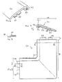
- Fig. 4A shows (in vertical cross-section) the "peg edge" of a mat 50 (assembled from interlocking Muovihaka tiles as previously detailed) interlocked to a complementary socket-type adaptor strip 10 by means of the tile pegs 52 penetrating the adaptor sockets 12.
- edging strip 30 is attached to the adaptor strip 10 by means of snapping the edging strip groove 34 (see Fig. 3) onto the adaptor strip ridge 14 (see Fig. 1) such that the barbs of the ridge 14 hook the groove edges 36 to lock the strips 30 and 10 together along their length.
- the lateral separation of the ridge 14 outwards (in the assembly) from the centre-line of the sockets 12 ensures that the edge 32 of the edging strip 30 is correctly located in relation to the "peg edge" of the mat 50.
- Fig. 4B shows (in vertical cross-section) the "socket edge" of the mat 50 interlocked to a complementary peg-type adaptor strip 20 by means of the adaptor pegs 22 penetrating the mat sockets 54.
- An appropriate length of edging strip 30 is attached to the adaptor strip 20 by means of snapping the edging strip groove 34 (see Fig. 3) onto the adaptor strip ridge 24 (see Fig. 2) such that the barbs of the ridge 24 hook the groove edges 36 to lock the strips 30 and 20 together along their length.
- peg-type adaptor strip 20 (of the six-peg type) attached to each of mat tiles along the "socket edge" side of the mat 50 which is to be edged by the strip 30, but fewer peg-type adaptor strips may be appropriate in certain circumstances.
- the lateral separation of the ridge 24 outwards (in the assembly) from the centre-line of the pegs 22 ensures that the edge 32 of the edging strip 30 is correctly located in relation to the "socket edge" of the mat 50.
- the junction of the two lengths of edging strip 30 at the corner of the mat 50 can be neatly formed by conventionally 45°-mitring the strips 30.
- mitred corners requires certain skills whereas it is relatively easy to cut the strip 30 at 90°, ie straight across. Accordingly, a preferred optional extra is shown in Fig. 5, in the form of a corner unit 60 for forming corner junctions between lengths of edging strip 30 attached to adjacent sides of the mat 50.
- the corner unit 50 is generally L-shaped in plan (Fig. 5) and has a cross-section (Figs. 6 and 7) which is substantially identical to the cross-section of the edging strip 30 (compare Figs. 6 and 7 with Fig. 3).
- the corner unit 50 has an inside edge 52 whose underside is formed with a downwardly open groove 54 having re-entrant edges 56 adapted to interlock with the barbs of the ridges 14 and 24 on the adaptor strips 10 and 20, such that the corner unit 50 can be attached to the adaptor strips 10 and 20 in the same manner as individual lengths of edging strip 30 are attached.
- the corner unit 50 is coupled to abutting ends of adjacent lengths of edging strip 30 by means of double tongues 58, 60 projecting from each end of the corner unit 50.
- the gaps between each pair of tongues 58 and 60 allows them to pass on either side of the foot 42 in each length of strip 30 (see the cross-section in Fig. 3 and note its substantial identity with the corner unit cross-section shown in Fig. 7).
Landscapes
- Engineering & Computer Science (AREA)
- Architecture (AREA)
- Civil Engineering (AREA)
- Structural Engineering (AREA)
- Ceramic Engineering (AREA)
- Chemical & Material Sciences (AREA)
- Carpets (AREA)
- Floor Finish (AREA)
Applications Claiming Priority (2)
| Application Number | Priority Date | Filing Date | Title |
|---|---|---|---|
| GB9700518 | 1997-01-11 | ||
| GBGB9700518.5A GB9700518D0 (en) | 1997-01-11 | 1997-01-11 | Edging system |
Publications (2)
| Publication Number | Publication Date |
|---|---|
| EP0857839A2 true EP0857839A2 (de) | 1998-08-12 |
| EP0857839A3 EP0857839A3 (de) | 1999-06-02 |
Family
ID=10805851
Family Applications (1)
| Application Number | Title | Priority Date | Filing Date |
|---|---|---|---|
| EP98300160A Withdrawn EP0857839A3 (de) | 1997-01-11 | 1998-01-12 | Randanordnung |
Country Status (2)
| Country | Link |
|---|---|
| EP (1) | EP0857839A3 (de) |
| GB (1) | GB9700518D0 (de) |
Cited By (6)
| Publication number | Priority date | Publication date | Assignee | Title |
|---|---|---|---|---|
| WO2000023674A3 (en) * | 1998-10-22 | 2000-07-13 | Sico Inc | Portable floor |
| GB2355994A (en) * | 1999-09-14 | 2001-05-09 | Ian Douglas Law | Edge trim for floor coverings |
| WO2002015765A1 (en) * | 2000-08-25 | 2002-02-28 | Construction Specialties (Uk) Ltd. | Floor mat |
| WO2007051591A1 (en) * | 2005-10-31 | 2007-05-10 | Handy Tiling Holding B.V. | System for setting tiles, tile assembly and joining element for use in the system, method for setting tiles, and tile floor repair method |
| GB2440141A (en) * | 2006-07-13 | 2008-01-23 | Vaughans Of Leicester Ltd | Edging tiles |
| EP2136685A4 (de) * | 2007-04-16 | 2012-03-21 | 3M Innovative Properties Co | Basis für eine bodenmatte |
Family Cites Families (7)
| Publication number | Priority date | Publication date | Assignee | Title |
|---|---|---|---|---|
| US3802144A (en) * | 1972-08-16 | 1974-04-09 | J Spica | Through- and under-draining flooring modules |
| DE3124529A1 (de) * | 1981-06-23 | 1983-01-05 | Heinrich Kampmann KG, 4450 Lingen | Fussabtritt-eingangsmatte |
| CA1191304A (en) * | 1983-02-23 | 1985-08-06 | Richard A. Morrison | Mat module with ramp strip |
| US4497858A (en) * | 1983-09-09 | 1985-02-05 | Andre Dupont | Tile for an entrance mat |
| US4654245A (en) * | 1984-08-29 | 1987-03-31 | Balco, Inc. | Roll up floor mat |
| DK89291D0 (da) * | 1991-05-13 | 1991-05-13 | Frank Bentzon | Gulvbelaegningssystem med sammenkoblige fliseelementer, navnlig plastfliser |
| IT240768Y1 (it) * | 1996-07-04 | 2001-04-11 | Cincla Srl | Elemento modulare per pavimentazioni componibili in materialeelastico |
-
1997
- 1997-01-11 GB GBGB9700518.5A patent/GB9700518D0/en active Pending
-
1998
- 1998-01-12 EP EP98300160A patent/EP0857839A3/de not_active Withdrawn
Cited By (9)
| Publication number | Priority date | Publication date | Assignee | Title |
|---|---|---|---|---|
| WO2000023674A3 (en) * | 1998-10-22 | 2000-07-13 | Sico Inc | Portable floor |
| US6128881A (en) * | 1998-10-22 | 2000-10-10 | Sico Incorporated | Portable floor |
| GB2355994A (en) * | 1999-09-14 | 2001-05-09 | Ian Douglas Law | Edge trim for floor coverings |
| WO2002015765A1 (en) * | 2000-08-25 | 2002-02-28 | Construction Specialties (Uk) Ltd. | Floor mat |
| WO2007051591A1 (en) * | 2005-10-31 | 2007-05-10 | Handy Tiling Holding B.V. | System for setting tiles, tile assembly and joining element for use in the system, method for setting tiles, and tile floor repair method |
| US8122670B2 (en) | 2005-10-31 | 2012-02-28 | Handy Tiling Holding B.V. | System for setting tiles, tile assembly and joining element for use in the system, method for setting tiles, and tile floor repair method |
| AU2006310743B2 (en) * | 2005-10-31 | 2012-03-22 | Handy Tiling Holding B.V. | System for setting tiles, tile assembly and joining element for use in the system, method for setting tiles, and tile floor repair method |
| GB2440141A (en) * | 2006-07-13 | 2008-01-23 | Vaughans Of Leicester Ltd | Edging tiles |
| EP2136685A4 (de) * | 2007-04-16 | 2012-03-21 | 3M Innovative Properties Co | Basis für eine bodenmatte |
Also Published As
| Publication number | Publication date |
|---|---|
| GB9700518D0 (en) | 1997-02-26 |
| EP0857839A3 (de) | 1999-06-02 |
Similar Documents
| Publication | Publication Date | Title |
|---|---|---|
| US8006443B2 (en) | Interlocking modular floor tile | |
| US10407920B2 (en) | Floor covering | |
| US9534399B2 (en) | Method of using interlocking mat with integral ramp | |
| US5797237A (en) | Flooring system | |
| US4468910A (en) | Mat module with ramp strip | |
| US8726602B2 (en) | Interlocking floor tile | |
| US20030180091A1 (en) | Floor board with coupling means | |
| US5630304A (en) | Adjustable interlock floor tile | |
| US20020119275A1 (en) | Modular mats and edging system therefor | |
| US20030093964A1 (en) | Floor grid system | |
| US7655290B2 (en) | Carpet tiles | |
| US20070022689A1 (en) | Plastic flooring with improved seal | |
| US9187910B2 (en) | Carpet tiling system and method of installation | |
| US20110229692A1 (en) | Base for a floor mat | |
| CN205777300U (zh) | 地板及地板铺装结构 | |
| EP0117966A2 (de) | Zusammensetzbare Bodenbelagplatte zur Herstellung von Böden und dergleichen | |
| GB2436570A (en) | Floorboard with rebated side and end edges | |
| JP2004036278A (ja) | 敷板連結具 | |
| US10287778B2 (en) | System for connection and fitting method between modules for floor coverings | |
| CN212729483U (zh) | 一种具有隐藏式扣合结构的地毯拼件及地毯 |
Legal Events
| Date | Code | Title | Description |
|---|---|---|---|
| PUAI | Public reference made under article 153(3) epc to a published international application that has entered the european phase |
Free format text: ORIGINAL CODE: 0009012 |
|
| AK | Designated contracting states |
Kind code of ref document: A2 Designated state(s): AT BE CH DE DK ES FI FR GB GR IE IT LI LU MC NL PT SE |
|
| AX | Request for extension of the european patent |
Free format text: AL;LT;LV;MK;RO;SI |
|
| PUAL | Search report despatched |
Free format text: ORIGINAL CODE: 0009013 |
|
| AK | Designated contracting states |
Kind code of ref document: A3 Designated state(s): AT BE CH DE DK ES FI FR GB GR IE IT LI LU MC NL PT SE |
|
| AX | Request for extension of the european patent |
Free format text: AL;LT;LV;MK;RO;SI |
|
| AKX | Designation fees paid | ||
| REG | Reference to a national code |
Ref country code: DE Ref legal event code: 8566 |
|
| STAA | Information on the status of an ep patent application or granted ep patent |
Free format text: STATUS: THE APPLICATION IS DEEMED TO BE WITHDRAWN |
|
| 18D | Application deemed to be withdrawn |
Effective date: 19991203 |