EP0857843A1 - Charnière de porte automobile - Google Patents
Charnière de porte automobile Download PDFInfo
- Publication number
- EP0857843A1 EP0857843A1 EP98300677A EP98300677A EP0857843A1 EP 0857843 A1 EP0857843 A1 EP 0857843A1 EP 98300677 A EP98300677 A EP 98300677A EP 98300677 A EP98300677 A EP 98300677A EP 0857843 A1 EP0857843 A1 EP 0857843A1
- Authority
- EP
- European Patent Office
- Prior art keywords
- hinge
- bore
- hinge pin
- journal
- pin
- Prior art date
- Legal status (The legal status is an assumption and is not a legal conclusion. Google has not performed a legal analysis and makes no representation as to the accuracy of the status listed.)
- Granted
Links
- 229920003266 Leaf® Polymers 0.000 claims abstract description 23
- 238000000926 separation method Methods 0.000 claims abstract description 4
- 230000004323 axial length Effects 0.000 claims description 6
- 238000003780 insertion Methods 0.000 claims description 5
- 230000037431 insertion Effects 0.000 claims description 5
- 238000006073 displacement reaction Methods 0.000 claims 3
- 229910001209 Low-carbon steel Inorganic materials 0.000 description 1
- 239000011324 bead Substances 0.000 description 1
- 238000010276 construction Methods 0.000 description 1
- 238000005553 drilling Methods 0.000 description 1
- 230000001050 lubricating effect Effects 0.000 description 1
- 239000000463 material Substances 0.000 description 1
- 239000002184 metal Substances 0.000 description 1
- 238000012986 modification Methods 0.000 description 1
- 230000004048 modification Effects 0.000 description 1
- 238000004381 surface treatment Methods 0.000 description 1
Images
Classifications
-
- E—FIXED CONSTRUCTIONS
- E05—LOCKS; KEYS; WINDOW OR DOOR FITTINGS; SAFES
- E05D—HINGES OR SUSPENSION DEVICES FOR DOORS, WINDOWS OR WINGS
- E05D5/00—Construction of single parts, e.g. the parts for attachment
- E05D5/10—Pins, sockets or sleeves; Removable pins
- E05D5/12—Securing pins in sockets, movably or not
- E05D5/127—Securing pins in sockets, movably or not by forcing the pin into the socket
-
- E—FIXED CONSTRUCTIONS
- E05—LOCKS; KEYS; WINDOW OR DOOR FITTINGS; SAFES
- E05D—HINGES OR SUSPENSION DEVICES FOR DOORS, WINDOWS OR WINGS
- E05D11/00—Additional features or accessories of hinges
- E05D11/0018—Anti-tamper devices
-
- E—FIXED CONSTRUCTIONS
- E05—LOCKS; KEYS; WINDOW OR DOOR FITTINGS; SAFES
- E05D—HINGES OR SUSPENSION DEVICES FOR DOORS, WINDOWS OR WINGS
- E05D5/00—Construction of single parts, e.g. the parts for attachment
- E05D5/02—Parts for attachment, e.g. flaps
- E05D5/04—Flat flaps
- E05D5/043—Flat flaps specially adapted for vehicles
-
- E—FIXED CONSTRUCTIONS
- E05—LOCKS; KEYS; WINDOW OR DOOR FITTINGS; SAFES
- E05Y—INDEXING SCHEME ASSOCIATED WITH SUBCLASSES E05D AND E05F, RELATING TO CONSTRUCTION ELEMENTS, ELECTRIC CONTROL, POWER SUPPLY, POWER SIGNAL OR TRANSMISSION, USER INTERFACES, MOUNTING OR COUPLING, DETAILS, ACCESSORIES, AUXILIARY OPERATIONS NOT OTHERWISE PROVIDED FOR, APPLICATION THEREOF
- E05Y2900/00—Application of doors, windows, wings or fittings thereof
- E05Y2900/50—Application of doors, windows, wings or fittings thereof for vehicles
- E05Y2900/53—Type of wing
- E05Y2900/531—Doors
Definitions
- the present invention relates to a hinge, in particular, a vehicle door hinge.
- Security vehicles as used for example for transporting money to/from banks need to be adapted such that forced entry into the vehicle is difficult.
- Hinges particularly hinges having hinge pins located on the outside of a vehicle can provide a relatively easy access route for forced entry by unauthorised removal of the hinge pin(s).
- a general aim of the present invention is to provide a hinge which is difficult to dismantle by removal of the hinge pin.
- a hinge having a first hinge leaf hingedly connected to a second hinge leaf for movement about a hinge axis, the hinge leaves being inter-engaged to prevent axial separation along the hinge axis, and at least one hinge pin extending along the hinge axis, the hinge pin having a terminal axial face located internally of one of the hinge leafs to prevent access thereto.
- the hinge pin has an enlarged head portion which is housed internally within one of the hinge leaves.
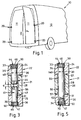
- FIG. 1 there is shown a vehicle 10 having a pair of rear doors 11. Each door 11 is hingedly connected to the vehicle body 12 via a pair of hinges 20 according to the present invention.
- the hinges 20 are located externally of the vehicle door 11 and body 12 and so are exposed to tampering by a potential intruder for unauthorised entry into the vehicle.
- each hinge 20 is adapted to deter tampering for unauthorised entry.
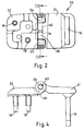
- the hinge 20 includes a pair of hinge leaves 21, 22 hingedly connected to another.
- hinge leaf 21 is intended to be secured to the vehicle door 11 and hinge leaf 22 is intended to be secured to the vehicle body 12.
- Hinge leaf 22 is provided with bolts 18 for securance to the body 12 and hinge leaf 21 is provided with an anchor plate 19 for securance to a door 11.
- Hinge leaf 22 includes a pair of spaced journal arms 24, 25 between which is received a journal arm 26 formed on leaf 21.
- a bore 28 is provided in arm 26 which extends throughout the entire axial length of arm 26.
- Journal arms 24, 25 are provided with axially aligned bores 30, 31 respectively which extend the entire axial length of each respective arm 24, 25.
- Each bore 30, 31 is stepped to define a wider portion 33, 34 located at the outer end of each respective bore and also to define an internal shoulder 35, 36 respectively.
- hinge pin 40 being located in bore 30 and extending partly into bore 28 from an upper end thereof and hinge pin 41 being located in bore 31 and extending partly into bore 28 from a lower end thereof.
- Each hinge pin 40, 41 is provided with an enlarged head 44, 45 respectively, each of which, in use, abuts against respective internal shoulders 35, 36.
- the axial length of each head 44, 45 is preferably chosen to be equal to or more preferably shorter than the axial length of the wider bore portion such that when in abutment with respective shoulders 35, 36 the head 44, 45 is completely housed within respective bore portion 33, 34. Accordingly, in use, only axial end faces 46, 47 of respective pin heads 44, 45 are accessible to a potential intruder.
- the heads 44, 45 are adapted, for example by suitable choice of metal or surface treatment, to be resistive to drilling.
- the pins 40, 41 may be made of mild steel which is case hardened.
- the length of pins 40, 41 are chosen such that their respective inner axial faces 52 are spaced from one another by a distance d when fully inserted. This ensures that each pin 40, 41 may be fully inserted to engage their respective shoulders 35, 36.
- each hinge pin 40, 41 is secured within respective bore 30, 31 so as to be non rotatably received therein and also resistive to axial withdrawal.
- securance is achieved by providing the circumferential faces of beads 44, 45 with a roughened surface which grips the internal wall of respective bore portions 33, 34 after insertion of the pins.
- the roughened surface may be defined for example by flutes 50 which preferably bite into the material of the hinges leaves during insertion.
- hinge pins 40, 41 are inserted into the hinge 10 in opposed axial directions, viz. as shown in Figure 3 hinge pin 40 is inserted downwardly and hinge pin 41 is inserted upwardly. Accordingly one hinge pin acts to block access to the inner axial face 52 of the other hinge pin and thereby prevent potential intruders from extracting either pin by pushing an implement against inner axial face 52.
- bore 28 is lined with a pair of self lubricating bushes 55, 56 each of which includes a flange 57 for providing a sliding bearing face between opposed faces on arms 24, 25 and 26.
- a simple hinge pin 140 is provided which extends downwardly through bore 28 and into bore 31.
- a cap member 70 of similar construction to the head 45 of hinge pin 41 is located within the wide bore portion 34 in order to block access to the inner axial end face 52 of the hinge pin 140.
- cap member 70 serves to close the outer end of bore 31 and that instead of providing cap member 70, bore 31 may be instead formed as a blind bore.
- interleafing between hinge leaves 21 and 22 is achieved by a single journal arm on leaf 21 and a pair of spaced journal arms on leaf 22. It will be appreciated that interleafing may be achieved by adopting a plurality of journal arms on leaf 21, each of which is interleafed with a pair of axially spaced journal arms on leaf 22. In such a case, the outermost journal arms on leaf 22 would be provided with the stepped bores.
Landscapes
- Engineering & Computer Science (AREA)
- Mechanical Engineering (AREA)
- Hinges (AREA)
- Hinge Accessories (AREA)
Applications Claiming Priority (2)
| Application Number | Priority Date | Filing Date | Title |
|---|---|---|---|
| GB9702003 | 1997-01-31 | ||
| GBGB9702003.6A GB9702003D0 (en) | 1997-01-31 | 1997-01-31 | A vehicle door hinge |
Publications (2)
| Publication Number | Publication Date |
|---|---|
| EP0857843A1 true EP0857843A1 (fr) | 1998-08-12 |
| EP0857843B1 EP0857843B1 (fr) | 2005-07-13 |
Family
ID=10806882
Family Applications (1)
| Application Number | Title | Priority Date | Filing Date |
|---|---|---|---|
| EP98300677A Expired - Lifetime EP0857843B1 (fr) | 1997-01-31 | 1998-01-30 | Charnière de porte automobile |
Country Status (6)
| Country | Link |
|---|---|
| US (1) | US6163929A (fr) |
| EP (1) | EP0857843B1 (fr) |
| DE (1) | DE69830813T2 (fr) |
| ES (1) | ES2245800T3 (fr) |
| GB (1) | GB9702003D0 (fr) |
| PT (1) | PT857843E (fr) |
Cited By (3)
| Publication number | Priority date | Publication date | Assignee | Title |
|---|---|---|---|---|
| EP1498218A2 (fr) | 2003-07-17 | 2005-01-19 | DGS Druckguss Systeme AG | Procédé de fabrication d'un élément fonctionnel à construction légère |
| KR100897333B1 (ko) | 2008-04-10 | 2009-05-15 | 현대자동차주식회사 | 도어힌지 기구 |
| EP2202373A1 (fr) * | 2008-12-23 | 2010-06-30 | Simonswerk, Gesellschaft mit beschränkter Haftung | Penture, notamment pour le domaine d'objets |
Families Citing this family (14)
| Publication number | Priority date | Publication date | Assignee | Title |
|---|---|---|---|---|
| US6490758B1 (en) * | 1999-04-22 | 2002-12-10 | Chuo Hatsujo Kabushiki Kaisha | Frictional hinge device |
| US6708371B2 (en) * | 2002-06-11 | 2004-03-23 | Illinois Tool Works Inc. | Positive retaining pivot pin |
| US20060273621A1 (en) * | 2005-06-06 | 2006-12-07 | Ventra Group, Inc. | Lift-off door hinge |
| US7805810B2 (en) * | 2006-10-05 | 2010-10-05 | Lawrence Andrew Hoffman | Multi leaf extendable gear hinge |
| US7832057B2 (en) * | 2006-10-05 | 2010-11-16 | The Hoffman Group International, Ltd. | Extendable multi-axis door hinge |
| GB0710613D0 (en) * | 2007-06-04 | 2007-07-11 | Hetherington Mark | Releasable hinge |
| US8443490B2 (en) * | 2007-06-05 | 2013-05-21 | Liberty Hardware Mfg. Corp. | Universal reversible gate hinges and method of assembly |
| US20100077565A1 (en) * | 2008-10-01 | 2010-04-01 | Wei-Kuo Huang | Hinge capable of being positioned at any angle |
| CA2773581C (fr) * | 2009-09-10 | 2014-02-25 | Toyota Shatai Kabushiki Kaisha | Charniere pour porte de vehicule |
| US9127876B2 (en) * | 2013-03-14 | 2015-09-08 | Electrolux Home Products, Inc. | Snap off center flipper mullion |
| DE202013002821U1 (de) * | 2013-03-25 | 2014-06-27 | Dieter Ramsauer | Scharnier |
| US9097048B2 (en) * | 2013-08-13 | 2015-08-04 | FlatZen, Inc. | Hinge mechanisms and foldable furniture |
| US10247230B2 (en) * | 2016-04-06 | 2019-04-02 | FlatZen, Inc. | Hinge mechanisms |
| US10184280B2 (en) * | 2016-06-02 | 2019-01-22 | Flex-N-Gate Advanced Product Development, Llc. | Automotive door hinge |
Citations (4)
| Publication number | Priority date | Publication date | Assignee | Title |
|---|---|---|---|---|
| US3390419A (en) * | 1965-11-05 | 1968-07-02 | Lawrence Brothers | Flush mounted arrangement of a hinge pintle |
| US4116514A (en) * | 1977-07-22 | 1978-09-26 | Lawrence Brothers, Inc. | Security hinge |
| FR2616173A1 (fr) * | 1987-06-03 | 1988-12-09 | Meen Dominique | Gond de haute securite |
| GB2287063A (en) * | 1994-03-02 | 1995-09-06 | Stanley Works | Concealed bearing hinge |
Family Cites Families (6)
| Publication number | Priority date | Publication date | Assignee | Title |
|---|---|---|---|---|
| US462204A (en) * | 1891-10-27 | Ments | ||
| US2500481A (en) * | 1945-07-18 | 1950-03-14 | John B Adler | Hinge structure |
| US4475266A (en) * | 1979-05-24 | 1984-10-09 | The Stanley Works | Non-handed two knuckle hinge |
| US4573239A (en) * | 1984-08-17 | 1986-03-04 | The Stanley Works | Three knuckle hinge with bushing inserts in center knuckle and method of making same |
| FR2610662B1 (fr) * | 1986-12-27 | 1990-07-06 | Scharwaechter Gmbh Co Kg | Charniere de porte decrochable |
| US4790047A (en) * | 1988-04-04 | 1988-12-13 | General Motors Corporation | Hinge bushing adjustment means for a hinge assembly |
-
1997
- 1997-01-31 GB GBGB9702003.6A patent/GB9702003D0/en active Pending
-
1998
- 1998-01-30 ES ES98300677T patent/ES2245800T3/es not_active Expired - Lifetime
- 1998-01-30 DE DE69830813T patent/DE69830813T2/de not_active Expired - Lifetime
- 1998-01-30 EP EP98300677A patent/EP0857843B1/fr not_active Expired - Lifetime
- 1998-01-30 PT PT98300677T patent/PT857843E/pt unknown
- 1998-02-02 US US09/017,007 patent/US6163929A/en not_active Expired - Lifetime
Patent Citations (4)
| Publication number | Priority date | Publication date | Assignee | Title |
|---|---|---|---|---|
| US3390419A (en) * | 1965-11-05 | 1968-07-02 | Lawrence Brothers | Flush mounted arrangement of a hinge pintle |
| US4116514A (en) * | 1977-07-22 | 1978-09-26 | Lawrence Brothers, Inc. | Security hinge |
| FR2616173A1 (fr) * | 1987-06-03 | 1988-12-09 | Meen Dominique | Gond de haute securite |
| GB2287063A (en) * | 1994-03-02 | 1995-09-06 | Stanley Works | Concealed bearing hinge |
Cited By (5)
| Publication number | Priority date | Publication date | Assignee | Title |
|---|---|---|---|---|
| EP1498218A2 (fr) | 2003-07-17 | 2005-01-19 | DGS Druckguss Systeme AG | Procédé de fabrication d'un élément fonctionnel à construction légère |
| AT412990B (de) * | 2003-07-17 | 2005-09-26 | Dgs Druckguss Systeme Ag | Verfahren zur herstellung eines leichtbau-funktionsteils und leichtbau-funktionsteil |
| KR100897333B1 (ko) | 2008-04-10 | 2009-05-15 | 현대자동차주식회사 | 도어힌지 기구 |
| EP2202373A1 (fr) * | 2008-12-23 | 2010-06-30 | Simonswerk, Gesellschaft mit beschränkter Haftung | Penture, notamment pour le domaine d'objets |
| DE102009011042A1 (de) * | 2008-12-23 | 2010-07-01 | Simonswerk, Gesellschaft mit beschränkter Haftung | Türband, insbesondere für den Objektbereich |
Also Published As
| Publication number | Publication date |
|---|---|
| DE69830813T2 (de) | 2005-12-22 |
| ES2245800T3 (es) | 2006-01-16 |
| US6163929A (en) | 2000-12-26 |
| DE69830813D1 (de) | 2005-08-18 |
| EP0857843B1 (fr) | 2005-07-13 |
| GB9702003D0 (en) | 1997-03-19 |
| PT857843E (pt) | 2005-10-31 |
Similar Documents
| Publication | Publication Date | Title |
|---|---|---|
| US6163929A (en) | Vehicle door hinge | |
| US5971515A (en) | Protected internal hinge for security safe | |
| US4725084A (en) | Door guard | |
| US4640052A (en) | Hinge bolt set | |
| US4280726A (en) | Keyless lockable security devices | |
| US3390419A (en) | Flush mounted arrangement of a hinge pintle | |
| US4839939A (en) | Security hinge with improved structural integrity with the electrical wires located along the pivot axis of the knuckles | |
| US7000290B1 (en) | Lockable hinge | |
| CA1113210A (fr) | Cheville de securite pour charnieres | |
| US20020074811A1 (en) | Bolt seal | |
| EP1256671B1 (fr) | Rosette pour serrure cylindrique | |
| EP2826933B1 (fr) | Serrure cylindrique équipé d'un pont de liaison | |
| US4688405A (en) | Concealed post lock | |
| US5769473A (en) | Apparatus for door restraining assembly | |
| EP0916793A1 (fr) | Une charnière du sûreté | |
| US5337453A (en) | Butt hinge pin lock | |
| US6866309B1 (en) | Security bolt latch apparatus and method | |
| DE60208306T2 (de) | Schloss mit Sicherheitsblock gegen Einbruch | |
| EP1722061B1 (fr) | Porte | |
| AU2004321977B8 (en) | A hinge | |
| US20030189341A1 (en) | Door jamb extension apparatus | |
| US4404916A (en) | Multiple entry closure for a safe or vault | |
| DE10236707B4 (de) | Vorrichtung für eine Tür | |
| EP0585735B1 (fr) | Serrure de fixation pour cylindre d'un verrou de sécurité | |
| US3398426A (en) | Safety hinges |
Legal Events
| Date | Code | Title | Description |
|---|---|---|---|
| PUAI | Public reference made under article 153(3) epc to a published international application that has entered the european phase |
Free format text: ORIGINAL CODE: 0009012 |
|
| AK | Designated contracting states |
Kind code of ref document: A1 Designated state(s): DE ES FR GB IT PT |
|
| AX | Request for extension of the european patent |
Free format text: AL;LT;LV;MK;RO;SI |
|
| 17P | Request for examination filed |
Effective date: 19990212 |
|
| AKX | Designation fees paid |
Free format text: DE ES FR GB IT PT |
|
| RBV | Designated contracting states (corrected) |
Designated state(s): DE ES FR GB IT PT |
|
| 17Q | First examination report despatched |
Effective date: 20001214 |
|
| RAP1 | Party data changed (applicant data changed or rights of an application transferred) |
Owner name: MULTIMATIC ADVANCED TECHNOLOGIES INC. |
|
| GRAP | Despatch of communication of intention to grant a patent |
Free format text: ORIGINAL CODE: EPIDOSNIGR1 |
|
| RAP1 | Party data changed (applicant data changed or rights of an application transferred) |
Owner name: MULTIMATIC ADVANCED TECHNOLOGIES INC. |
|
| GRAS | Grant fee paid |
Free format text: ORIGINAL CODE: EPIDOSNIGR3 |
|
| GRAA | (expected) grant |
Free format text: ORIGINAL CODE: 0009210 |
|
| AK | Designated contracting states |
Kind code of ref document: B1 Designated state(s): DE ES FR GB IT PT |
|
| REG | Reference to a national code |
Ref country code: GB Ref legal event code: FG4D |
|
| REF | Corresponds to: |
Ref document number: 69830813 Country of ref document: DE Date of ref document: 20050818 Kind code of ref document: P |
|
| REG | Reference to a national code |
Ref country code: PT Ref legal event code: SC4A Effective date: 20050909 |
|
| REG | Reference to a national code |
Ref country code: ES Ref legal event code: FG2A Ref document number: 2245800 Country of ref document: ES Kind code of ref document: T3 |
|
| ET | Fr: translation filed | ||
| PLBE | No opposition filed within time limit |
Free format text: ORIGINAL CODE: 0009261 |
|
| STAA | Information on the status of an ep patent application or granted ep patent |
Free format text: STATUS: NO OPPOSITION FILED WITHIN TIME LIMIT |
|
| 26N | No opposition filed |
Effective date: 20060418 |
|
| REG | Reference to a national code |
Ref country code: FR Ref legal event code: PLFP Year of fee payment: 19 |
|
| REG | Reference to a national code |
Ref country code: FR Ref legal event code: PLFP Year of fee payment: 20 |
|
| PGFP | Annual fee paid to national office [announced via postgrant information from national office to epo] |
Ref country code: ES Payment date: 20161214 Year of fee payment: 20 Ref country code: FR Payment date: 20161215 Year of fee payment: 20 |
|
| PGFP | Annual fee paid to national office [announced via postgrant information from national office to epo] |
Ref country code: DE Payment date: 20170125 Year of fee payment: 20 |
|
| PGFP | Annual fee paid to national office [announced via postgrant information from national office to epo] |
Ref country code: PT Payment date: 20170123 Year of fee payment: 20 Ref country code: GB Payment date: 20170125 Year of fee payment: 20 |
|
| PGFP | Annual fee paid to national office [announced via postgrant information from national office to epo] |
Ref country code: IT Payment date: 20170123 Year of fee payment: 20 |
|
| REG | Reference to a national code |
Ref country code: DE Ref legal event code: R071 Ref document number: 69830813 Country of ref document: DE |
|
| REG | Reference to a national code |
Ref country code: GB Ref legal event code: PE20 Expiry date: 20180129 |
|
| PG25 | Lapsed in a contracting state [announced via postgrant information from national office to epo] |
Ref country code: GB Free format text: LAPSE BECAUSE OF EXPIRATION OF PROTECTION Effective date: 20180129 |
|
| REG | Reference to a national code |
Ref country code: ES Ref legal event code: FD2A Effective date: 20180508 |
|
| PG25 | Lapsed in a contracting state [announced via postgrant information from national office to epo] |
Ref country code: PT Free format text: LAPSE BECAUSE OF EXPIRATION OF PROTECTION Effective date: 20180206 |
|
| PG25 | Lapsed in a contracting state [announced via postgrant information from national office to epo] |
Ref country code: ES Free format text: LAPSE BECAUSE OF EXPIRATION OF PROTECTION Effective date: 20180131 |