EP0857873A2 - Fahrradpumpe - Google Patents
Fahrradpumpe Download PDFInfo
- Publication number
- EP0857873A2 EP0857873A2 EP98200517A EP98200517A EP0857873A2 EP 0857873 A2 EP0857873 A2 EP 0857873A2 EP 98200517 A EP98200517 A EP 98200517A EP 98200517 A EP98200517 A EP 98200517A EP 0857873 A2 EP0857873 A2 EP 0857873A2
- Authority
- EP
- European Patent Office
- Prior art keywords
- valve
- connecting piece
- pump
- hose
- bicycle
- Prior art date
- Legal status (The legal status is an assumption and is not a legal conclusion. Google has not performed a legal analysis and makes no representation as to the accuracy of the status listed.)
- Withdrawn
Links
Images

Classifications
-
- F—MECHANICAL ENGINEERING; LIGHTING; HEATING; WEAPONS; BLASTING
- F04—POSITIVE - DISPLACEMENT MACHINES FOR LIQUIDS; PUMPS FOR LIQUIDS OR ELASTIC FLUIDS
- F04B—POSITIVE-DISPLACEMENT MACHINES FOR LIQUIDS; PUMPS
- F04B33/00—Pumps actuated by muscle power, e.g. for inflating
- F04B33/005—Pumps actuated by muscle power, e.g. for inflating specially adapted for inflating tyres of non-motorised vehicles, e.g. cycles, tricycles
-
- B—PERFORMING OPERATIONS; TRANSPORTING
- B60—VEHICLES IN GENERAL
- B60C—VEHICLE TYRES; TYRE INFLATION; TYRE CHANGING; CONNECTING VALVES TO INFLATABLE ELASTIC BODIES IN GENERAL; DEVICES OR ARRANGEMENTS RELATED TO TYRES
- B60C29/00—Arrangements of tyre-inflating valves to tyres or rims; Accessories for tyre-inflating valves, not otherwise provided for
- B60C29/06—Accessories for tyre-inflating valves, e.g. housings, guards, covers for valve caps, locks, not otherwise provided for
- B60C29/064—Hose connections for pneumatic tyres, e.g. to spare wheels
-
- B—PERFORMING OPERATIONS; TRANSPORTING
- B62—LAND VEHICLES FOR TRAVELLING OTHERWISE THAN ON RAILS
- B62J—CYCLE SADDLES OR SEATS; AUXILIARY DEVICES OR ACCESSORIES SPECIALLY ADAPTED TO CYCLES AND NOT OTHERWISE PROVIDED FOR, e.g. ARTICLE CARRIERS OR CYCLE PROTECTORS
- B62J11/00—Supporting arrangements specially adapted for fastening specific devices to cycles, e.g. supports for attaching maps
- B62J11/02—Supporting arrangements specially adapted for fastening specific devices to cycles, e.g. supports for attaching maps for pumps
Definitions
- the invention relates to a bicycle pump provided with an elongated pump housing, with a pump piston which is reciprocatingly movable within the pump housing by means of a piston rod, and with a pump hose secured to the pump housing, said pump hose at its free end being provided with a connecting device for connecting the pump hose to a tyre valve provided with a ring.
- the connecting device is provided with a connecting piece of a resilient material, which can be pushed over the valve, said connecting piece surrounding at least part of the valve when placed on the valve, and being provided with a thickening, which can be deformed by means of a shell-shaped member being slidable over the connecting piece, in such a manner that said thickening is sealingly pressed against the outer circumference of the valve upon being deformed.
- a satisfactory enclosure of at least part of the valve can be effected by means of the connecting device, whilst at the same time an adequate fixation of the connecting device to the valve can be realized.
- the connecting piece and the shell-shaped means being slidable over the connecting piece may thereby extend concentrically about the extension of the central axis of the pump hose, so that no impeding projections are required for connecting the pump hose.
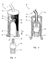
- Figure 1 shows the upper end of the valve of a bicycle tyre and one end of the pump hose, with a connecting device for connecting the pump hose to the valve.
- Figure 2 shows the parts illustrated in Figure 1 in a second position.
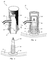
- Figures 3 and 4 show, in a similar manner as in Figures 1 and 2, a second embodiment of a connecting device.
- Figures 5 and 6 show, in a similar manner as in Figures 1 and 2, a third embodiment of a connecting device.
- a connecting device 38 is provided at a free end of a hose 29 of a bicycle pump (not shown), in order to connect the hose to a conventional valve 37 provided with a knurled ring 36 of a bicycle tyre.
- the connecting device 38 comprises a connecting piece 39 made of a resilient material, which comprises a cylindrical shell 40, which is closed at its upper end by a closing part 41, in the centre of which an elongated recess 42 is provided, which is open at its bottom end.
- the closing part 41 is at its bottom end provided with a downwardly tapered part, which extends into the space surrounded by the shell 40.
- the recess 42 is in open communication with a stepped bore 43 extending perpendicularly to the longitudinal axis of the closing part 41, in which the end of the pump hose 29 of the bicycle pump is secured, for example by glueing or vulcanizing.
- the shell 40 is provided with a circular flange 44 at its free end, which in the unloaded position shown in Figure 1 gradually widens towards the outside and towards its free end relative to the longitudinal central axis of the closing part.
- the connecting piece 39 is surrounded by a shell-shaped means 45 which is closed at one end, said shell-shaped means being movable in the longitudinal direction of the connecting piece 39 relative to said connecting piece 39.
- the pump hose 29 is passed through a slotted hole 46 provided in the wall of the shell-shaped means 45.
- the shell-shaped means 45 is provided with an enlarged flange 47 at its open bottom end, against whose inner boundary edge the flange 44 of the connecting piece 39 abuts in the manner shown in Figure 1, in the position ready for pushing the connecting piece 39 onto the valve 37.
- the connecting piece 39 may be pushed onto the valve 37 in the direction according to the arrow D, whereby the bottom end of the tapered portion of the closing part 41 will come to lie on top of the knurled ring 36 at one stage. Upon being pushed further downwards said bottom end of the closing part will be firmly pressed against the upper side of the usual knurled ring 36, so as to effect an air-tight sealing at that location, beside the sealing that has already been effected by the cylindrical shell 40 surrounding the knurled ring 36.
- the flange 44 can spring back again from the position shown in Figure 2 to the position shown in Figure 1, after which the connecting device 38 may be removed from the valve.
- the hose and the connecting device 38 When not in use the hose and the connecting device 38 may be stowed away in the chamber 12, which can be closed by means of the cover 13.
- Figures 3 and 4 show a variation on the connecting device described above with reference to Figures 1 and 2.
- the parts in Figures 3 and 4 that correspond with the parts shown in Figures 1 and 2 are thereby provided with the same reference numerals and will not be described again.
- the shell 40 of this embodiment is at its upper end provided with a connecting piece 48 which is slightly tapered in upward direction and which is integral with the shell 40, said connecting piece connecting the shell to a wall part 49, which extends substantially perpendicularly to the longitudinal direction of the shell 40 in unloaded condition.
- a passage 50 is formed in the centre of said wall part 49, to which passage the hose 29 is connected, in the manner illustrated in the Figures.
- the hose 29 is thereby passed through a hole 51 provided in the upper wall of the shell-shaped means 45.
- this connecting device may be pushed over the valve, in such a manner that the wall part 49 will come to abut against the upper boundary surface 52 of the valve.
- the shell-shaped means When the shell-shaped means is pushed further downwards (arrow D), the wall part 49 will be pressed firmly against said surface 52 with a certain amount of deformation, so as to effect an airtight connection.
- the enlarged flange 47 will snap under the knurled ring 36 in the manner described above and illustrated in Figure 4, in order to secure the connecting device 38 to the valve 37, whilst likewise an airtight connection has been obtained between the hose 29 and the valve by means of the deformed wall part 49.
- the closing device may be removed in a simple manner again by moving the shell-shaped means in a direction opposite to the arrow D.
- FIGS 5 and 6 show a so-called French valve 53, which is fixed with respect to a rim 55 of a bicycle wheel or the like by means of a clamping ring 54 screwed onto said valve 53.
- a French valve of this type is provided with a valve mechanism, which may be brought to a position suitable for inflating the bicycle tyre on which said valve 53 is mounted by rotating a ring 56, and which may be closed by rotating said ring 56 in opposite direction.
- the connecting device 38' shown in Figures 5 and 6 is provided with a connecting piece 39', in a similar manner as the connecting device described above and illustrated in Figures 1 and 2, and with a shell-shaped means 45' surrounding said connecting piece. A detailed description of the connecting device 38' will not be necessary, therefore.
- the shell-shaped means 45' will be moved with respect to the connecting piece 39', as a result of which the circular flange 44' is deformed and pressed firmly against the outer circumference of the valve 53 at a position spaced from the ring 54, as shown in Figure 6, as a result of which an airtight connection of the connecting piece 39' to the valve 53 can be effected at that location as well.
- the bicycle tyre may be inflated in the usual manner, whereby the air is admitted to the tyre through the valve mechanism, which has been opened prior to placing the connecting device 38' on the valve 53, by rotating the ring 56.
Landscapes
- Engineering & Computer Science (AREA)
- Mechanical Engineering (AREA)
- General Engineering & Computer Science (AREA)
- Compressors, Vaccum Pumps And Other Relevant Systems (AREA)
- Reciprocating Pumps (AREA)
- Details Of Reciprocating Pumps (AREA)
Applications Claiming Priority (3)
| Application Number | Priority Date | Filing Date | Title |
|---|---|---|---|
| NL9300278 | 1993-02-12 | ||
| NL9300278A NL9300278A (nl) | 1993-02-12 | 1993-02-12 | Fietspomp. |
| EP94907012A EP0683863B1 (de) | 1993-02-12 | 1994-02-02 | Fahrradpumpe |
Related Parent Applications (1)
| Application Number | Title | Priority Date | Filing Date |
|---|---|---|---|
| EP94907012A Division EP0683863B1 (de) | 1993-02-12 | 1994-02-02 | Fahrradpumpe |
Publications (2)
| Publication Number | Publication Date |
|---|---|
| EP0857873A2 true EP0857873A2 (de) | 1998-08-12 |
| EP0857873A3 EP0857873A3 (de) | 1998-10-07 |
Family
ID=19862061
Family Applications (2)
| Application Number | Title | Priority Date | Filing Date |
|---|---|---|---|
| EP98200517A Withdrawn EP0857873A3 (de) | 1993-02-12 | 1994-02-02 | Fahrradpumpe |
| EP94907012A Expired - Lifetime EP0683863B1 (de) | 1993-02-12 | 1994-02-02 | Fahrradpumpe |
Family Applications After (1)
| Application Number | Title | Priority Date | Filing Date |
|---|---|---|---|
| EP94907012A Expired - Lifetime EP0683863B1 (de) | 1993-02-12 | 1994-02-02 | Fahrradpumpe |
Country Status (6)
| Country | Link |
|---|---|
| EP (2) | EP0857873A3 (de) |
| AT (1) | ATE170953T1 (de) |
| AU (1) | AU6046494A (de) |
| DE (1) | DE69413205T2 (de) |
| NL (1) | NL9300278A (de) |
| WO (1) | WO1994018452A2 (de) |
Families Citing this family (1)
| Publication number | Priority date | Publication date | Assignee | Title |
|---|---|---|---|---|
| ES2836249T3 (es) * | 2017-11-27 | 2021-06-24 | N Verhoeven Holding B V | Un dispositivo para acoplar una bomba de neumático a una válvula de un neumático, un conjunto del dispositivo y boquillas de bomba y un método para aumentar la presión de un neumático |
Family Cites Families (12)
| Publication number | Priority date | Publication date | Assignee | Title |
|---|---|---|---|---|
| BE371431A (de) * | ||||
| DE387672C (de) * | 1924-01-02 | Gustav Michelfelder | Mit einem aufklappbaren Fuss versehene Luftpumpe | |
| BE403713A (de) * | ||||
| BE503697A (de) * | ||||
| FR421368A (fr) * | 1910-10-12 | 1911-02-21 | Emile Duchemin | Pompe et raccord de pompe pour gonfler les pneumatiques et autres |
| GB180804A (en) * | 1921-03-21 | 1922-06-08 | Dunlop Rubber Co | Improvements in or relating to connecting or attaching devices for tyre inflating pumps or the like |
| FR572729A (fr) * | 1923-01-05 | 1924-06-12 | Dian & Cie | Raccord de valve à bloquage rapide |
| GB222236A (en) * | 1923-07-06 | 1924-10-02 | Giovanni Modelli | Improvements in connectors for tyre pumps and the like |
| GB295553A (en) * | 1928-02-02 | 1928-08-16 | Karl Barat | Push-on nipple coupling and its fastening means |
| CH236906A (de) * | 1943-10-27 | 1945-03-15 | Ag Metallwarenfabrik | Velopumpe. |
| CH261549A (de) * | 1947-07-10 | 1949-05-15 | Lindenberger Adolf | Luftpumpe, insbesondere für Fahrräder. |
| FR2091718A7 (de) * | 1970-05-23 | 1972-01-14 | Campagnolo Tullio |
-
1993
- 1993-02-12 NL NL9300278A patent/NL9300278A/nl not_active Application Discontinuation
-
1994
- 1994-02-02 EP EP98200517A patent/EP0857873A3/de not_active Withdrawn
- 1994-02-02 WO PCT/NL1994/000025 patent/WO1994018452A2/en not_active Ceased
- 1994-02-02 EP EP94907012A patent/EP0683863B1/de not_active Expired - Lifetime
- 1994-02-02 AU AU60464/94A patent/AU6046494A/en not_active Abandoned
- 1994-02-02 DE DE69413205T patent/DE69413205T2/de not_active Expired - Fee Related
- 1994-02-02 AT AT94907012T patent/ATE170953T1/de not_active IP Right Cessation
Also Published As
| Publication number | Publication date |
|---|---|
| EP0683863B1 (de) | 1998-09-09 |
| ATE170953T1 (de) | 1998-09-15 |
| EP0683863A1 (de) | 1995-11-29 |
| AU6046494A (en) | 1994-08-29 |
| WO1994018452A3 (en) | 1994-09-29 |
| DE69413205D1 (de) | 1998-10-15 |
| NL9300278A (nl) | 1994-09-01 |
| DE69413205T2 (de) | 1999-05-12 |
| EP0857873A3 (de) | 1998-10-07 |
| WO1994018452A2 (en) | 1994-08-18 |
Similar Documents
| Publication | Publication Date | Title |
|---|---|---|
| US4342710A (en) | Apparatus for aerating beverages | |
| US4407125A (en) | Liquid pressure apparatus | |
| EP0707895B1 (de) | Hülse zur Befestigung eines durch Hand zu betätigenden Pumpenaggregates auf eine Glasflasche | |
| GB1602141A (en) | Inflation valves | |
| US5816284A (en) | Tire valve extension attachment | |
| JPH082362A (ja) | エアバッグモジュール | |
| US4927397A (en) | Raft inflation valve | |
| US3977576A (en) | Spray can and valve construction | |
| US2777490A (en) | Closure device for flexible-walled hollow articles | |
| CA2390968A1 (en) | Inflation/deflation valve for a bag to be filled with air | |
| US5325886A (en) | Inflation and pressure indicator apparatus for tires | |
| EP0857873A2 (de) | Fahrradpumpe | |
| US5760296A (en) | Cooling system pressure testing for leak detection | |
| US6351990B1 (en) | Low tire pressure light indicator | |
| JPS6224141Y2 (de) | ||
| US6273303B1 (en) | Fixing member for fixing a dispenser device to the neck of a container, a dispenser using such a fixing member, and a method of performing such fixing | |
| US5333653A (en) | Inflatable manhole sealing device | |
| CA2091386A1 (en) | Pneumatic tires having improved uniformity at tire-wheel assembled state | |
| US4252077A (en) | Pneumatic sound generator | |
| US6874524B2 (en) | Air valve capable of preventing air leakage when a connection head of an inflation device is removed | |
| US6412758B1 (en) | Rolling-lobe air spring | |
| EP0849513A2 (de) | Klappe für aufblasbaren Dingi | |
| US4077456A (en) | Simplified valve for tubeless tire | |
| EP1334885A3 (de) | Aufblasvorrichtung und ihre Verschluss-Befestigungsstruktur | |
| US5295603A (en) | Pressure lid container |
Legal Events
| Date | Code | Title | Description |
|---|---|---|---|
| PUAI | Public reference made under article 153(3) epc to a published international application that has entered the european phase |
Free format text: ORIGINAL CODE: 0009012 |
|
| AC | Divisional application: reference to earlier application |
Ref document number: 683863 Country of ref document: EP |
|
| AK | Designated contracting states |
Kind code of ref document: A2 Designated state(s): AT BE CH DE DK ES FR GB GR IE IT LI LU MC NL PT SE |
|
| PUAL | Search report despatched |
Free format text: ORIGINAL CODE: 0009013 |
|
| AK | Designated contracting states |
Kind code of ref document: A3 Designated state(s): AT BE CH DE DK ES FR GB GR IE IT LI LU MC NL PT SE |
|
| STAA | Information on the status of an ep patent application or granted ep patent |
Free format text: STATUS: THE APPLICATION IS DEEMED TO BE WITHDRAWN |
|
| 18D | Application deemed to be withdrawn |
Effective date: 19990408 |