EP0857945A2 - Capteur à fluide magnétique - Google Patents
Capteur à fluide magnétique Download PDFInfo
- Publication number
- EP0857945A2 EP0857945A2 EP98101263A EP98101263A EP0857945A2 EP 0857945 A2 EP0857945 A2 EP 0857945A2 EP 98101263 A EP98101263 A EP 98101263A EP 98101263 A EP98101263 A EP 98101263A EP 0857945 A2 EP0857945 A2 EP 0857945A2
- Authority
- EP
- European Patent Office
- Prior art keywords
- ferrofluid
- housing
- sensor
- magnet
- recited
- Prior art date
- Legal status (The legal status is an assumption and is not a legal conclusion. Google has not performed a legal analysis and makes no representation as to the accuracy of the status listed.)
- Granted
Links
Images

Classifications
-
- G—PHYSICS
- G01—MEASURING; TESTING
- G01C—MEASURING DISTANCES, LEVELS OR BEARINGS; SURVEYING; NAVIGATION; GYROSCOPIC INSTRUMENTS; PHOTOGRAMMETRY OR VIDEOGRAMMETRY
- G01C9/00—Measuring inclination, e.g. by clinometers, by levels
- G01C9/10—Measuring inclination, e.g. by clinometers, by levels by using rolling bodies, e.g. spheres, cylinders, mercury droplets
-
- G—PHYSICS
- G01—MEASURING; TESTING
- G01P—MEASURING LINEAR OR ANGULAR SPEED, ACCELERATION, DECELERATION, OR SHOCK; INDICATING PRESENCE, ABSENCE, OR DIRECTION, OF MOVEMENT
- G01P15/00—Measuring acceleration; Measuring deceleration; Measuring shock, i.e. sudden change of acceleration
- G01P15/02—Measuring acceleration; Measuring deceleration; Measuring shock, i.e. sudden change of acceleration by making use of inertia forces using solid seismic masses
- G01P15/08—Measuring acceleration; Measuring deceleration; Measuring shock, i.e. sudden change of acceleration by making use of inertia forces using solid seismic masses with conversion into electric or magnetic values
- G01P15/105—Measuring acceleration; Measuring deceleration; Measuring shock, i.e. sudden change of acceleration by making use of inertia forces using solid seismic masses with conversion into electric or magnetic values by magnetically sensitive devices
-
- G—PHYSICS
- G01—MEASURING; TESTING
- G01P—MEASURING LINEAR OR ANGULAR SPEED, ACCELERATION, DECELERATION, OR SHOCK; INDICATING PRESENCE, ABSENCE, OR DIRECTION, OF MOVEMENT
- G01P15/00—Measuring acceleration; Measuring deceleration; Measuring shock, i.e. sudden change of acceleration
- G01P15/02—Measuring acceleration; Measuring deceleration; Measuring shock, i.e. sudden change of acceleration by making use of inertia forces using solid seismic masses
- G01P15/08—Measuring acceleration; Measuring deceleration; Measuring shock, i.e. sudden change of acceleration by making use of inertia forces using solid seismic masses with conversion into electric or magnetic values
- G01P15/11—Measuring acceleration; Measuring deceleration; Measuring shock, i.e. sudden change of acceleration by making use of inertia forces using solid seismic masses with conversion into electric or magnetic values by inductive pick-up
-
- G—PHYSICS
- G01—MEASURING; TESTING
- G01C—MEASURING DISTANCES, LEVELS OR BEARINGS; SURVEYING; NAVIGATION; GYROSCOPIC INSTRUMENTS; PHOTOGRAMMETRY OR VIDEOGRAMMETRY
- G01C9/00—Measuring inclination, e.g. by clinometers, by levels
- G01C9/02—Details
- G01C9/06—Electric or photoelectric indication or reading means
- G01C2009/064—Electric or photoelectric indication or reading means inductive
-
- G—PHYSICS
- G01—MEASURING; TESTING
- G01C—MEASURING DISTANCES, LEVELS OR BEARINGS; SURVEYING; NAVIGATION; GYROSCOPIC INSTRUMENTS; PHOTOGRAMMETRY OR VIDEOGRAMMETRY
- G01C9/00—Measuring inclination, e.g. by clinometers, by levels
- G01C9/10—Measuring inclination, e.g. by clinometers, by levels by using rolling bodies, e.g. spheres, cylinders, mercury droplets
- G01C2009/102—Measuring inclination, e.g. by clinometers, by levels by using rolling bodies, e.g. spheres, cylinders, mercury droplets cylinders
-
- G—PHYSICS
- G01—MEASURING; TESTING
- G01C—MEASURING DISTANCES, LEVELS OR BEARINGS; SURVEYING; NAVIGATION; GYROSCOPIC INSTRUMENTS; PHOTOGRAMMETRY OR VIDEOGRAMMETRY
- G01C9/00—Measuring inclination, e.g. by clinometers, by levels
- G01C9/18—Measuring inclination, e.g. by clinometers, by levels by using liquids
- G01C2009/187—Measuring inclination, e.g. by clinometers, by levels by using liquids magnetic, e.g. ferromagnetic
Definitions
- This invention relates to a ferrofluid sensor subassembly that can be employed for detection and measurement of vibrations, acceleration and tilt.
- Sensors may be used to detect and measure a variety of conditions including vibrations, acceleration and tilt.
- Sensor subassemblies are available in a variety of forms including mechanical, electrical and ferrofluidic.
- Mechanical vibration and acceleration sensors use pendulums or moving elements.
- Electrical sensors use mercury slugs or cantilever beams to make or break an electrical contact. In a mercury-based sensor, the mercury is sealed in a glass vessel. Because of a high surface tension, the mercury does not stick to the glass vessel, but responds quickly to slight vibrations. However, mercury has the disadvantage of being a hazardous material.
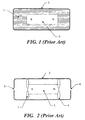
- Ferrofluidic sensor subassembly consists of an axially polarized permanent magnet located in a non-magnetic housing completely filled with ferrofluid as illustrated in Figure 1 and discussed in detail in U.S. Patent No. 4,667,414.
- Ferrofluid 1 is a colloidal mixture of magnetic particles suspended in a liquid carrier, such as oil. The particles are coated with a surfactant such that the carrier wets the particles and maintains them in suspension.
- Ferrofluid 1 is sealed inside the non-magnetic housing 2 which includes a mechanism that allows the ferrofluid to expand (not shown in Figure 1).
- housing 2 may incorporate flexible diaphragms.
- Magnet 3 is free to move inside housing 2 and is suspended in the housing 2 by the ferrofluid 1 which becomes trapped in the magnetic field produced by the magnet 3.
- the movement of magnet 3 can be detected by inductive coils (not shown) wound around housing 2 or by a Hall element (not shown). With the appropriate electronic signal processing, the inclination or acceleration of magnet 3 can be measured.
- the ferrofluid 1 is generally fairly viscous due to the presence of the oil carrier.
- the viscosity of the ferrofluid 1 produces a viscous drag on the magnet 3 and thus slows response time of the device. Since the ferrofluid viscosity is a function of temperature, the response time is temperature dependent. Furthermore, a small increase in the mass of the magnet 3 occurs over time due to sedimentation of ferrofluid particles on the magnet surface. This affects the calibration of the device.
- the magnet 3 in this device is centered in a housing or tube 2 by two ferrofluid rings 1,4 situated on either end of the magnet 3 and held by the magnetic field. There is no physical contact between the magnet 3 and the housing 2.
- the magnet 3 can slide freely because the ferrofluid rings 1,4 act as friction-less bearings inside the housing 2.
- the ferrofluid rings 1,4 also form low pressure seals between the magnet 3 and the walls of the housing 2. Accordingly, the ends of the housing 2 generally have small openings 5,6 to release any pressure build-up of air due to the motion of the magnet 3.
- This device does not have the response time and calibration problems discussed above.
- the magnet 3 moves, it leaves behind a thin layer of ferrofluid adhering to the wall of the housing 2 due to surface tension.
- the ferrofluid in the ferrofluid rings 1,4 becomes depleted and the levitation force produced by the ferrofluid is reduced.
- the length of the housing 2 is relatively long so that the magnet 3 excursion is long or the magnet 3 movement is rapid, a significant amount of the ferrofluid may be lost from the ferrofluid rings 1,4 during each travel of the magnet 3 through the housing 2, thereby rapidly depleting the ferrofluid rings 1,4.
- the rings 1,4 are sufficiently depleted, magnet 3 will no longer be suspended resulting in failure of the device. Additionally, over time, ferrofluid may be lost through the vent holes 5,6 in the housing resulting in a short product life.
- a ferrofluid sensor assembly constructed in accordance with the principles of the present invention includes a permanent magnet which is supported in a hermetically-sealed housing by ferrofluid rings at each end of the magnet.
- the housing is large enough that the ferrofluid rings do not seal the end of the magnet against the walls of the housing.
- the housing walls are coated with a thin film of immiscible liquid on which the ferrofluid rides.
- the housing is sealed, there are no evaporative losses of the ferrofluid.
- the magnet moves, there is no residual film of ferrofluid left behind on the surface of the housing because the ferrofluid rides on the thin film of preferentially wetting liquid and does not wet the surface of the housing walls.
- the magnet is permanently suspended by the two ferrofluid rings and slides without friction and there is no degradation with time.
- the housing is filled with a non-magnetic liquid that is immiscible with the ferrofluid.
- the nonmagnetic liquid wets the walls of the housing and provides a surface such that the ferrofluid rides on the thin film of the nonmagnetic liquid.
- the non-magnetic fluid is selected to have low viscosity, so that the magnet has a much quicker response time than the prior art device which is filled with ferrofluid.
- Figure 1 is a schematic diagram of a prior art ferrofluid sensor subassembly which is completely filled with ferrofluid to suspend a sensor magnet.
- FIG. 2 is a schematic diagram of another prior art ferrofluid sensor subassembly which utilizes ferrofluid rings to suspend the sensor magnet.
- FIG. 3 is a schematic diagram of a ferrofluid sensor subassembly constructed in accordance with the principles of the present invention which utilizes ferrofluid rings to suspend the sensor magnet in a low viscosity fluid filled housing.
- Figure 4 is a schematic diagram of a ferrofluid sensor subassembly constructed in accordance with the principles of the present invention which illustrates sensing the position of the sensor magnet by inductive coils.
- Figure 5 is a schematic diagram of a ferrofluid sensor subassembly constructed in accordance with the principles of the present invention which illustrates sensing the position of the sensor magnet by Hall-effect devices.
- an hermetically-sealed housing 2 encloses an axially-polarized permanent magnet 3 and a nonmagnetic liquid 7.
- Magnet 3 is supported in housing 2 by ferrofluid rings 1 and 4 at each end of the magnet and the levitation force produced by the ferrofluid. Rings 1,4 are held in place at the ends of magnet 3 by the magnetic field produced by magnet 3.
- housing 2 is large enough that the ferrofluid rings 1,4 do not seal the ends of magnet 3 against the walls of nonmagnetic housing 2, which may be made of glass or plastic. Therefore, as the magnet 3 moves the liquid 7 is free to move around the magnet 3.
- Housing 2 is filled with a nonmagnetic fluid 7 that is immiscible with the ferrofluid in rings 1 and 4.
- the ferrofluid carrier liquid neither mixes with, nor chemically reacts with, the ferrofluid in the rings 1 and 4.
- the nonmagnetic liquid 7 preferentially wets the inner walls of the housing 2 such that the ferrofluid in rings 1 and 4, which would otherwise stick to the dry wall of the housing now rides on the thin film of the nonmagnetic liquid 7.
- another nonwetting film could be used on the inner walls of the housing.
- Such a material might, for example, comprise a film of TEFLON® or other suitable lubricant.
- Non-magnetic liquids can be used for liquid 7.
- Water is the preferred liquid, however, because of its high freezing point (0° C), it is preferable to mix the water with any alcohol such as isopropanol which has a freezing point of - 89.5° C.
- the temperature range of the sensor subassembly can thus be extended to lower temperatures.
- Water is immiscible with a typical ferrofluid carrier liquid.
- a carrier liquid might be a low molecular weight fluorocarbon liquid, which is chemically known as perfluoropolyether.
- the housing 2 is sealed, there are no evaporative losses from the ferrofluid carrier.
- the magnet 3 moves, there is no residual film of ferrofluid left behind on the surface of the housing 1 from the ferrofluid rings 1 and 4.
- the magnet 3 is permanently suspended by the two ferrofluid rings 1 and 4 and there is no degradation with time.
- Figure 4 illustrates a mechanism for sensing the position of the sensor magnet.
- the ferrofluid sensor assembly is constructed in accordance with the principles of the present invention in the same manner as shown in Figure 3 and includes a permanent magnet 3 which is supported in a hermetically-sealed housing 2 by ferrofluid rings 1 and 4 at each end of the magnet 3.
- the housing 2 is filled with a non-magnetic liquid 7 that is immiscible with the ferrofluid in rings 1 and 4.
- Figure 4 illustrates inductive coils 8 positioned around the housing 2 which sense the position of the sensor magnet 3.
- the position of the magnet in the sensor subassembly influences the inductance of coil 8 thereby generating an electrical signal which depends on the position of the magnet 3.
- Conventional electronic processing of this signal yields information about the vibrational level or inclination of the housing 2.
- Figure 5 illustrates an embodiment in which the position of sensor magnet 3 is sensed by Hall-effect elements 9 and 10. These operate in a conventional manner to detect changes in the magnetic field generated by magnet 3 and thereby determine its position.
- the nonmagnetic liquid 7 was a 50/50 by volume mixture of deionized water and isopropanol.
- Magnet 3 consisted of an axially-polarized cylindrical Alnico 5 magnet with a length of 11 mm and a diameter of 2.5 mm.
- the ferrofluid in rings 1 and 4 comprised a fluorocarbon-based ferrofluid with a magnetization of 325 gauss, and a viscosity less than 5 cp at 27° C.
- the housing tube 2 was first rinsed with the 50/50 water isopropanol mixture 7 two times and then it was filled with the 50/50 water isopropanol mixture 7.
- the magnet 3 was cleaned with the mixture 7.
- the magnet 3 was cleaned with heptane and isopropanol to remove impurities and then placed inside the tube 2.
- About 25 microliters of ferrofluid was added to each pole of the magnet with a micro dispenser.
- the open end of the tube 2 was then sealed with a plug. A small air bubble was, however, left inside the tube 2 to allow for expansion of the mixture 7.
- the aforementioned assembly was tested over a period of six months to determine if the ferrofluid colloid stability was affected by the immiscible mixture 7.
- the assembly was also monitored to determine if the ferrofluid and the mixture 7 intermixed over time. Further examinations were conducted to ascertain if the movement of the magnet left a thin film of ferrofluid on the wall of the tube. None of these problems were, however, found to occur in the assembly.
- the magnet was responsive to the vibrations at the end of the test period just the same way as it was on the first day of the test period.
- This aforementioned assembly was also tested as a vibration sensor replacing a mercury-based sensor and was found to be a suitable replacement.
- the magnet in the assembly provides a high conductivity similar to the high conductivity of mercury and the levitation of the magnet on the ferrofluid rings in the presence of the low viscosity immiscible liquid provides a magnet movement similar to the low-friction movement of the mercury slug.
- housing and magnet have been described as having cylindrical shapes, these elements could have shapes with other cross-sections.
Landscapes
- Physics & Mathematics (AREA)
- General Physics & Mathematics (AREA)
- Engineering & Computer Science (AREA)
- Radar, Positioning & Navigation (AREA)
- Remote Sensing (AREA)
- Investigating Or Analyzing Materials By The Use Of Magnetic Means (AREA)
- Sealing Using Fluids, Sealing Without Contact, And Removal Of Oil (AREA)
- Soft Magnetic Materials (AREA)
- Measurement Of Length, Angles, Or The Like Using Electric Or Magnetic Means (AREA)
- Transmission And Conversion Of Sensor Element Output (AREA)
- Measurement Of Mechanical Vibrations Or Ultrasonic Waves (AREA)
- Compositions Of Macromolecular Compounds (AREA)
Applications Claiming Priority (2)
| Application Number | Priority Date | Filing Date | Title |
|---|---|---|---|
| US799121 | 1997-02-11 | ||
| US08/799,121 US5780741A (en) | 1997-02-11 | 1997-02-11 | Sensor employing a sliding magnet suspended on ferrofluid |
Publications (3)
| Publication Number | Publication Date |
|---|---|
| EP0857945A2 true EP0857945A2 (fr) | 1998-08-12 |
| EP0857945A3 EP0857945A3 (fr) | 2000-03-08 |
| EP0857945B1 EP0857945B1 (fr) | 2003-07-30 |
Family
ID=25175086
Family Applications (1)
| Application Number | Title | Priority Date | Filing Date |
|---|---|---|---|
| EP98101263A Expired - Lifetime EP0857945B1 (fr) | 1997-02-11 | 1998-01-26 | Capteur à fluide magnétique |
Country Status (4)
| Country | Link |
|---|---|
| US (1) | US5780741A (fr) |
| EP (1) | EP0857945B1 (fr) |
| JP (1) | JPH10239096A (fr) |
| DE (1) | DE69816680T2 (fr) |
Cited By (2)
| Publication number | Priority date | Publication date | Assignee | Title |
|---|---|---|---|---|
| DE19942363C2 (de) * | 1999-09-04 | 2002-01-31 | Bayerische Motoren Werke Ag | Induktiver Beschleunigungssensor |
| US6374673B1 (en) | 2000-03-01 | 2002-04-23 | Texas Components Corporation | Velocity sensor |
Families Citing this family (41)
| Publication number | Priority date | Publication date | Assignee | Title |
|---|---|---|---|---|
| US7296469B2 (en) * | 2000-02-24 | 2007-11-20 | Innalabs Technologies, Inc. | Magnetofluidic accelerometer with active suspension |
| US7191652B2 (en) * | 2000-02-24 | 2007-03-20 | Innalabs Technologies, Inc. | Magnetofluidic accelerometer with partial filling of cavity with magnetic fluid |
| WO2001073449A1 (fr) * | 2000-03-27 | 2001-10-04 | Shozo Hirayama | Accelerometre triaxial utilisant un fluide magnetique |
| GB2387910B (en) * | 2002-01-23 | 2005-11-09 | Autonnic Res Ltd | Electromagnetic inclinometer |
| US6768230B2 (en) | 2002-02-19 | 2004-07-27 | Rockwell Scientific Licensing, Llc | Multiple magnet transducer |
| US7288860B2 (en) * | 2002-02-19 | 2007-10-30 | Teledyne Licensing, Inc. | Magnetic transducer with ferrofluid end bearings |
| US6812583B2 (en) * | 2002-02-19 | 2004-11-02 | Rockwell Scientific Licensing, Llc | Electrical generator with ferrofluid bearings |
| US6812598B2 (en) | 2002-02-19 | 2004-11-02 | Rockwell Scientific Licensing, Llc | Multiple magnet transducer with differential magnetic strengths |
| US6628017B1 (en) * | 2002-08-06 | 2003-09-30 | Jacob Chass | Ferrofluidic, electromagnetic power supply |
| US7009310B2 (en) * | 2004-01-12 | 2006-03-07 | Rockwell Scientific Licensing, Llc | Autonomous power source |
| US7143648B2 (en) * | 2004-09-29 | 2006-12-05 | Ferrolabs, Inc. | Magnetofluidic accelerometer with capacitive sensing of inertial body position |
| WO2007021039A1 (fr) * | 2005-08-17 | 2007-02-22 | G-Device Corporation | Capteur de vibration incliné compact et son procédé de fabrication |
| DE102006007900B4 (de) * | 2006-02-18 | 2008-04-03 | Stefan Gräf | Ferrofluid-Neigungs- oder -Beschleunigungssensor |
| DE102006061198B4 (de) * | 2006-05-31 | 2019-07-18 | Asm Automation Sensorik Messtechnik Gmbh | Neigungssensor |
| JP2008209235A (ja) * | 2007-02-26 | 2008-09-11 | Nohmi Bosai Ltd | 加速度センサ |
| JP2008209234A (ja) * | 2007-02-26 | 2008-09-11 | Nohmi Bosai Ltd | 加速度センサ |
| US20090212645A1 (en) * | 2008-02-27 | 2009-08-27 | Infineon Technologies Ag | Electronic device for harvesting energy |
| DE102009006368B3 (de) * | 2009-01-28 | 2010-07-01 | Asm Automation Sensorik Messtechnik Gmbh | Neigungssensor |
| US8056246B1 (en) * | 2010-07-19 | 2011-11-15 | National Semiconductor Corporation | Ferrofluidic orientation sensor and method of forming the sensor |
| DE102010061898B4 (de) * | 2010-11-24 | 2016-07-07 | Endress + Hauser Gmbh + Co. Kg | Druckmittler und Druckmessaufnehmer mit einem Druckmittler |
| US9250070B2 (en) * | 2011-11-16 | 2016-02-02 | Keith Robert Wootten | Rugged three-axis inclinometer |
| US9850733B2 (en) | 2013-12-19 | 2017-12-26 | Halliburton Energy Services, Inc. | Self-assembling packer |
| SG11201602016UA (en) | 2013-12-19 | 2016-04-28 | Halliburton Energy Services Inc | Intervention tool for delivering self-assembling repair fluid |
| US9797222B2 (en) | 2013-12-30 | 2017-10-24 | Halliburton Energy Services, Inc. | Ferrofluid tool for enhancing magnetic fields in a wellbore |
| MX2016006952A (es) | 2013-12-30 | 2016-09-27 | Halliburton Energy Services Inc | Herramienta de ferrofluido para el aislamiento de objetos en un pozo. |
| US10047590B2 (en) | 2013-12-30 | 2018-08-14 | Halliburton Energy Services, Inc. | Ferrofluid tool for influencing electrically conductive paths in a wellbore |
| EP3027851A1 (fr) | 2013-12-30 | 2016-06-08 | Halliburton Energy Services, Inc. | Outil à ferrofluides permettant la mise en oeuvre de structures modifiables dans les puits de forage |
| US10598810B2 (en) * | 2014-05-19 | 2020-03-24 | Halliburton Energy Services, Inc. | Optical magnetic field sensor units for a downhole environment |
| GB2555279B (en) | 2015-06-30 | 2021-03-24 | Halliburton Energy Services Inc | Outflow control device for creating a packer |
| CN105527459A (zh) * | 2016-02-04 | 2016-04-27 | 河北工业大学 | 一种霍尔式磁性液体加速度传感器 |
| CN106838089B (zh) * | 2016-12-14 | 2019-03-01 | 北京交通大学 | 一种未充满型磁性液体一阶浮力原理减振器 |
| RU171502U1 (ru) * | 2017-03-21 | 2017-06-02 | федеральное государственное бюджетное образовательное учреждение высшего образования "Ивановский государственный энергетический университет имени В.И. Ленина" (ИГЭУ) | Магнитожидкостное устройство для определения угла наклона |
| CN107064833A (zh) * | 2017-04-18 | 2017-08-18 | 蔡立汉 | 一种简易的旋磁测验器 |
| US10620335B2 (en) | 2017-05-02 | 2020-04-14 | Ascension Technology Corporation | Rotating frequencies of transmitters |
| US10779892B2 (en) | 2017-08-10 | 2020-09-22 | Northern Digital Inc. | Tracking a cylindrical opening |
| US11529193B2 (en) | 2017-08-10 | 2022-12-20 | Northern Digital Inc. | Tracking a sensor that includes a ferrofluid |
| CN107631719A (zh) * | 2017-08-24 | 2018-01-26 | 云南靖创液态金属热控技术研发有限公司 | 一种基于液态金属的倾角传感器 |
| CN109738051B (zh) * | 2018-12-28 | 2021-08-06 | 重庆工商大学 | 一种磁流变液自适应超声传感器及检测方法 |
| CN113295262A (zh) * | 2021-04-16 | 2021-08-24 | 北京交通大学 | 一种基于磁性液体的柔性可穿戴传感装置 |
| CN114047250B (zh) * | 2021-11-25 | 2023-03-17 | 西安电子科技大学 | 金属管道裂纹检测传感器及检测方法 |
| SE545560C2 (en) * | 2022-11-07 | 2023-10-24 | Husqvarna Ab | System for determining an orientation of an inertial-magnetic measurement unit using magnetic fluid |
Family Cites Families (4)
| Publication number | Priority date | Publication date | Assignee | Title |
|---|---|---|---|---|
| GB8424053D0 (en) * | 1984-09-22 | 1984-10-31 | Russell M K | Direction-finding devices |
| US4706498A (en) * | 1985-09-23 | 1987-11-17 | Ferrotec, Inc. | Apparatus and method for measuring movement |
| JPH0697236B2 (ja) * | 1987-05-30 | 1994-11-30 | 株式会社日本自動車部品総合研究所 | 加速度センサ |
| US5452520A (en) * | 1994-03-14 | 1995-09-26 | Ferrofluidics Corporation | Ferrofluid inclinometer |
-
1997
- 1997-02-11 US US08/799,121 patent/US5780741A/en not_active Expired - Fee Related
-
1998
- 1998-01-26 DE DE69816680T patent/DE69816680T2/de not_active Expired - Fee Related
- 1998-01-26 EP EP98101263A patent/EP0857945B1/fr not_active Expired - Lifetime
- 1998-02-10 JP JP10046293A patent/JPH10239096A/ja not_active Withdrawn
Cited By (2)
| Publication number | Priority date | Publication date | Assignee | Title |
|---|---|---|---|---|
| DE19942363C2 (de) * | 1999-09-04 | 2002-01-31 | Bayerische Motoren Werke Ag | Induktiver Beschleunigungssensor |
| US6374673B1 (en) | 2000-03-01 | 2002-04-23 | Texas Components Corporation | Velocity sensor |
Also Published As
| Publication number | Publication date |
|---|---|
| DE69816680D1 (de) | 2003-09-04 |
| EP0857945B1 (fr) | 2003-07-30 |
| EP0857945A3 (fr) | 2000-03-08 |
| JPH10239096A (ja) | 1998-09-11 |
| DE69816680T2 (de) | 2004-06-03 |
| US5780741A (en) | 1998-07-14 |
Similar Documents
| Publication | Publication Date | Title |
|---|---|---|
| US5780741A (en) | Sensor employing a sliding magnet suspended on ferrofluid | |
| US5908987A (en) | Sensor employing a sliding ferrofluid mass in a coated, non-wetting, housing | |
| Bailey | Lesser known applications of ferrofluids | |
| US5117693A (en) | Liquid level sensor | |
| US20020124765A1 (en) | Method and apparatus for magnetic levitation | |
| US6557412B1 (en) | Non-fouling liquid level control | |
| US6813946B1 (en) | Liquid sensing | |
| DeGraff et al. | Ferrofluid transformer-based tilt sensor | |
| US20070214889A1 (en) | Magnetofluidic unidirectional accelerometer | |
| US7191652B2 (en) | Magnetofluidic accelerometer with partial filling of cavity with magnetic fluid | |
| US5490425A (en) | Ferrofluid pressure sensor and warning device | |
| CN112394197A (zh) | 一种摆式加速度计 | |
| KR100519138B1 (ko) | 자기플로트형태의액체레벨표시장치 | |
| RU2115091C1 (ru) | Магнитожидкостное устройство для определения угла наклона (варианты) | |
| US3520196A (en) | Fluid rotor angular accelerometer | |
| US3212341A (en) | Accelerometer apparatus | |
| US4669316A (en) | Differential-pressure apparatus employing a resonant force sensor | |
| JP2003177051A (ja) | 液面検出装置 | |
| US3602049A (en) | Fluid accelerometer | |
| JPS63109374A (ja) | センサ | |
| JP3190978B2 (ja) | 加速度センサー | |
| GB2076159A (en) | Displacement Transducer | |
| CN115047382B (zh) | 一种基于磁性液体密封的磁场测量装置及方法 | |
| US5661238A (en) | Bi-stable liquid indicator | |
| US5854552A (en) | Moving magnet indicating instruments with a plurality of damping fluid migration barriers |
Legal Events
| Date | Code | Title | Description |
|---|---|---|---|
| PUAI | Public reference made under article 153(3) epc to a published international application that has entered the european phase |
Free format text: ORIGINAL CODE: 0009012 |
|
| AK | Designated contracting states |
Kind code of ref document: A2 Designated state(s): DE FR GB IT SE |
|
| PUAL | Search report despatched |
Free format text: ORIGINAL CODE: 0009013 |
|
| AK | Designated contracting states |
Kind code of ref document: A3 Designated state(s): AT BE CH DE DK ES FI FR GB GR IE IT LI LU MC NL PT SE |
|
| RIC1 | Information provided on ipc code assigned before grant |
Free format text: 7G 01C 9/10 A, 7G 01C 9/06 B, 7G 01P 15/03 B, 7G 01P 15/08 B |
|
| 17P | Request for examination filed |
Effective date: 20000908 |
|
| AKX | Designation fees paid |
Free format text: DE FR GB IT SE |
|
| 17Q | First examination report despatched |
Effective date: 20020624 |
|
| GRAH | Despatch of communication of intention to grant a patent |
Free format text: ORIGINAL CODE: EPIDOS IGRA |
|
| GRAH | Despatch of communication of intention to grant a patent |
Free format text: ORIGINAL CODE: EPIDOS IGRA |
|
| GRAA | (expected) grant |
Free format text: ORIGINAL CODE: 0009210 |
|
| AK | Designated contracting states |
Designated state(s): DE FR GB IT SE |
|
| REG | Reference to a national code |
Ref country code: GB Ref legal event code: FG4D |
|
| RAP2 | Party data changed (patent owner data changed or rights of a patent transferred) |
Owner name: FERROTEC (USA) CORPORATION |
|
| REF | Corresponds to: |
Ref document number: 69816680 Country of ref document: DE Date of ref document: 20030904 Kind code of ref document: P |
|
| REG | Reference to a national code |
Ref country code: SE Ref legal event code: TRGR |
|
| PGFP | Annual fee paid to national office [announced via postgrant information from national office to epo] |
Ref country code: SE Payment date: 20040109 Year of fee payment: 7 |
|
| PGFP | Annual fee paid to national office [announced via postgrant information from national office to epo] |
Ref country code: FR Payment date: 20040120 Year of fee payment: 7 |
|
| PG25 | Lapsed in a contracting state [announced via postgrant information from national office to epo] |
Ref country code: GB Free format text: LAPSE BECAUSE OF NON-PAYMENT OF DUE FEES Effective date: 20040126 |
|
| ET | Fr: translation filed | ||
| PLBE | No opposition filed within time limit |
Free format text: ORIGINAL CODE: 0009261 |
|
| STAA | Information on the status of an ep patent application or granted ep patent |
Free format text: STATUS: NO OPPOSITION FILED WITHIN TIME LIMIT |
|
| 26N | No opposition filed |
Effective date: 20040504 |
|
| GBPC | Gb: european patent ceased through non-payment of renewal fee |
Effective date: 20040126 |
|
| PG25 | Lapsed in a contracting state [announced via postgrant information from national office to epo] |
Ref country code: SE Free format text: LAPSE BECAUSE OF NON-PAYMENT OF DUE FEES Effective date: 20050127 |
|
| EUG | Se: european patent has lapsed | ||
| PG25 | Lapsed in a contracting state [announced via postgrant information from national office to epo] |
Ref country code: FR Free format text: LAPSE BECAUSE OF NON-PAYMENT OF DUE FEES Effective date: 20050930 |
|
| REG | Reference to a national code |
Ref country code: FR Ref legal event code: ST |
|
| PGFP | Annual fee paid to national office [announced via postgrant information from national office to epo] |
Ref country code: IT Payment date: 20060131 Year of fee payment: 9 |
|
| PGFP | Annual fee paid to national office [announced via postgrant information from national office to epo] |
Ref country code: DE Payment date: 20070131 Year of fee payment: 10 |
|
| PG25 | Lapsed in a contracting state [announced via postgrant information from national office to epo] |
Ref country code: DE Free format text: LAPSE BECAUSE OF NON-PAYMENT OF DUE FEES Effective date: 20080801 |
|
| PG25 | Lapsed in a contracting state [announced via postgrant information from national office to epo] |
Ref country code: IT Free format text: LAPSE BECAUSE OF NON-PAYMENT OF DUE FEES Effective date: 20070126 |