EP0857953A1 - Messrad in einer Messvorrichtung - Google Patents
Messrad in einer Messvorrichtung Download PDFInfo
- Publication number
- EP0857953A1 EP0857953A1 EP97850021A EP97850021A EP0857953A1 EP 0857953 A1 EP0857953 A1 EP 0857953A1 EP 97850021 A EP97850021 A EP 97850021A EP 97850021 A EP97850021 A EP 97850021A EP 0857953 A1 EP0857953 A1 EP 0857953A1
- Authority
- EP
- European Patent Office
- Prior art keywords
- impeller
- radius
- vanes
- outer edge
- inlet tube
- Prior art date
- Legal status (The legal status is an assumption and is not a legal conclusion. Google has not performed a legal analysis and makes no representation as to the accuracy of the status listed.)
- Granted
Links
- 239000000463 material Substances 0.000 claims abstract description 19
- 230000000630 rising effect Effects 0.000 claims abstract 5
- 238000005259 measurement Methods 0.000 claims description 7
- 239000002245 particle Substances 0.000 description 17
- 230000001133 acceleration Effects 0.000 description 2
- 238000010586 diagram Methods 0.000 description 2
- 239000013590 bulk material Substances 0.000 description 1
- 239000012530 fluid Substances 0.000 description 1
- 239000013072 incoming material Substances 0.000 description 1
Images

Classifications
-
- G—PHYSICS
- G01—MEASURING; TESTING
- G01F—MEASURING VOLUME, VOLUME FLOW, MASS FLOW OR LIQUID LEVEL; METERING BY VOLUME
- G01F1/00—Measuring the volume flow or mass flow of fluid or fluent solid material wherein the fluid passes through a meter in a continuous flow
- G01F1/76—Devices for measuring mass flow of a fluid or a fluent solid material
- G01F1/78—Direct mass flowmeters
- G01F1/80—Direct mass flowmeters operating by measuring pressure, force, momentum, or frequency of a fluid flow to which a rotational movement has been imparted
- G01F1/84—Coriolis or gyroscopic mass flowmeters
- G01F1/845—Coriolis or gyroscopic mass flowmeters arrangements of measuring means, e.g., of measuring conduits
- G01F1/8454—Coriolis or gyroscopic mass flowmeters arrangements of measuring means, e.g., of measuring conduits rotating or rotatingly suspended measuring conduits
-
- G—PHYSICS
- G01—MEASURING; TESTING
- G01F—MEASURING VOLUME, VOLUME FLOW, MASS FLOW OR LIQUID LEVEL; METERING BY VOLUME
- G01F1/00—Measuring the volume flow or mass flow of fluid or fluent solid material wherein the fluid passes through a meter in a continuous flow
- G01F1/76—Devices for measuring mass flow of a fluid or a fluent solid material
- G01F1/78—Direct mass flowmeters
- G01F1/80—Direct mass flowmeters operating by measuring pressure, force, momentum, or frequency of a fluid flow to which a rotational movement has been imparted
Definitions
- the present invention relates to an apparatus for measuring a mass flow, in particular bulk material or a fluid, and the invention especially relates to an impeller arrangement used in a measuring device in which the mass flow rate is measured by using the Coriolis measuring principle.
- the particles to be measured are subjected to tangential acceleration in a whirling impeller, and the torque exerted on the vanes of the impeller in reaction to the Coriolis force of accelerated particles is being measured as an indication of the mass flow rate.
- the object of our above European patent application was to avoid measurement errors, due to uneven distribution of the material to be measured.
- the object of the present invention is therefore to further improve the measurement accuracy of the material introduced into the impeller from the inlet tube by modifying the shape of the impeller.
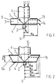
- Fig. 1 shows a schematic side view of a conventional impeller and an inlet tube for a mass flow measuring device
- Fig. 2 shows schematically a side view corresponding to Fig. 1 but with an impeller according to the invention
- Fig. 3 shows a diagram showing the relation between height H and radius R of the impeller
- Fig. 4 shows schematically a side view of an impeller according to the invention and made for a large material flow.
- the part of the device shown in the drawings is intended to be a part of a complete device for measuring a mass flow of the kind described in our copending European patent application No. 96850202.1, but in these drawings is only shown the impeller 1.
- the other parts relating to the measuring device can have the same, but also alternative, designs as those shown in our previous application.
- the impeller 1 is mounted for rotation around a vertical shaft 2, rotating in a direction shown by the arrow.
- the impeller 1 is provided with vanes 3 leading to the circumferential edge of the impeller 1, for guiding the material to be measured from the central area out from the impeller 1 via the vanes 3.
- the bottom of the impeller 1 is closed by a lower plate 4, and the top of the impeller 1 is closed by an upper plate 5, having a central opening above which the end of an inlet tube 6, supplying the material to be measured, ends.
- the present invention involves another way to solve the problem of minimizing the measurement errors referred to above.
- the distribution of the inflowing material into the measuring device can with the present invention be arbitrary or improved by any of the devices defined in any other of our European patent applications filed simultaneously herewith.
- the measurement errors can be minimized if the size of outer radius R 2 of the impeller 1 used for the measurement is varied.
- the impeller vanes 3 are assumed to have a height H increasing from the center of the impeller 1 until reaching the radius of the tube 6 leading the material into the impeller 1.
- Material particles entering the measuring device are falling down in the central part of the impeller 1 and rebounding from the center and due to the centrifugal force the particles are thrown substantially horizontally along any of the impeller vanes 3 towards the outer diameter R 2 of the impeller 1.
- the particles leave the impeller at its lower edge, which has a certain outer radius.
- Material particles that are entering the impeller 1 close to wall of the inlet tube 6 are thrown towards the upper edge of an impeller vane and are also deflected horizontally.
- the diameter of the impeller can in relation to the lower edge have a larger radius at its upper part. The increased radius gives rise to an extra acceleration distance compensating for that the radial point of impact results in a shorter distance than that from the impeller center.
- M torque
- n axis speed of rotation
- R 2 outer radius of the impeller
- R 1 inner radius from which the particles or the flow meet the impeller surface in or round it's centre.
- impeller vanes are made with varying outer diameter following the equation above, the influence of different point of impact for the incoming particles is eliminated.
- the diameter of the impeller should be kept constant irrespective of the magnitude of the material flow.
- the diameter of the incoming tube is increasing with increasing maximum flow, and consequently the vanes 3 extend along a shorter part of the impeller radius, but at the same time the height H of the vanes 3 increase.
- Fig. 1 is as stated above shown the conditions in an ordinary impeller in which the outer diameter R 2 for all heights of the impeller is constant, and parallel with the shaft 2.
- the inner edge of the impeller vanes 3 is successively increasing from the center of the impeller to the inner radius of the inlet tube 6.
- the outer edge 8 of the vanes is as stated above parallel with the shaft 2 and the center line 9, around which the impeller 1 rotates.
- the line 10 is shown a flow line for a particle entering the measuring device close to the center of the inlet tube 6, and falling into the impeller near its center, from which the same particle will follow the line 11 close to the bottom 4 along a vane 3 when passing out to the circumferential edge of the impeller.
- the line 12 shown a flow line for a particle entering the measuring device close to the wall of the inlet tube 6, and falling into the impeller off its center, from which the same particle will follow the line 13 close to the top 5 along a vane 3 when passing out to the circumferential edge of the impeller. It is quite obvious that the shorter distance (R 2 - R 1 ) the particle following line 13 is in contact with the vane 3 will lead to another force on the vane than a particle following the line 11.
- Fig. 2 is shown a view similar to the one in Fig. 1, but the impeller is in this case made in accordance with the present invention, and consequently the outer diameter of the impeller 1 increases from R 2 at the bottom to R xm at the top of the vanes 3. Correspondingly the outer edge 14 of the vanes 3 continuously or successively increases from the bottom 4 to the top 5.
- the flow line for a particle entering the flow measuring device at a distance R 1x from the center line 9 of the impeller 1, and horizontally follows the flow line 16 for escaping the impeller at a distance R xm from the center line 9.
- the enclosed area corresponds to the profile the vane 3 should have to eliminate the influence of different point of impact for the incoming particles.
- Fig. 4 is shown the proper form of the impeller for a large material flow.
- the inlet tube 6 has a large radius in relation to the radius of the upper plate 5.
- the height H of the impeller 1 is increased in relation to the impeller radius, whereby the vanes become proportionately shorter.
- the inner radius R 1 the becomes more important, but the influence is eliminated in that the outer edge 14 has an increasing radius.
- an impeller formed according to the present invention it will be possible to make an impeller having a big height and no area reducing device in the inlet, and nevertheless minimize the influence of an uneven distribution of the incoming flow of material.
Landscapes
- Physics & Mathematics (AREA)
- Fluid Mechanics (AREA)
- General Physics & Mathematics (AREA)
- Measuring Volume Flow (AREA)
Priority Applications (3)
| Application Number | Priority Date | Filing Date | Title |
|---|---|---|---|
| DE69724581T DE69724581T2 (de) | 1997-02-11 | 1997-02-11 | Massendurchflussmesser |
| EP97850021A EP0857953B1 (de) | 1997-02-11 | 1997-02-11 | Massendurchflussmesser |
| US09/021,937 US6033184A (en) | 1997-02-11 | 1998-02-11 | Impeller arrangement in a measuring device |
Applications Claiming Priority (1)
| Application Number | Priority Date | Filing Date | Title |
|---|---|---|---|
| EP97850021A EP0857953B1 (de) | 1997-02-11 | 1997-02-11 | Massendurchflussmesser |
Publications (2)
| Publication Number | Publication Date |
|---|---|
| EP0857953A1 true EP0857953A1 (de) | 1998-08-12 |
| EP0857953B1 EP0857953B1 (de) | 2003-09-03 |
Family
ID=8230950
Family Applications (1)
| Application Number | Title | Priority Date | Filing Date |
|---|---|---|---|
| EP97850021A Expired - Lifetime EP0857953B1 (de) | 1997-02-11 | 1997-02-11 | Massendurchflussmesser |
Country Status (3)
| Country | Link |
|---|---|
| US (1) | US6033184A (de) |
| EP (1) | EP0857953B1 (de) |
| DE (1) | DE69724581T2 (de) |
Cited By (1)
| Publication number | Priority date | Publication date | Assignee | Title |
|---|---|---|---|---|
| DE10041433A1 (de) * | 2000-08-23 | 2002-03-14 | Flumesys Gmbh Fluidmes Und Sys | Vorrichtung zur Messung eines Masse-Stromes |
Citations (1)
| Publication number | Priority date | Publication date | Assignee | Title |
|---|---|---|---|---|
| EP0146902A2 (de) * | 1983-12-21 | 1985-07-03 | Claus Friedrich | Messvorrichtung zur kontinuierlichen Gewichtserfassung von Materialströmen |
Family Cites Families (3)
| Publication number | Priority date | Publication date | Assignee | Title |
|---|---|---|---|---|
| US2877649A (en) * | 1955-07-14 | 1959-03-17 | American Radiator & Standard | Coriolis mass flowmeter |
| US3224079A (en) * | 1964-12-28 | 1965-12-21 | Ruth D Mayne | Method for manufacture of turbine type blower wheels |
| JPS5551995A (en) * | 1978-10-09 | 1980-04-16 | Toshiba Corp | Blower |
-
1997
- 1997-02-11 DE DE69724581T patent/DE69724581T2/de not_active Expired - Lifetime
- 1997-02-11 EP EP97850021A patent/EP0857953B1/de not_active Expired - Lifetime
-
1998
- 1998-02-11 US US09/021,937 patent/US6033184A/en not_active Expired - Lifetime
Patent Citations (1)
| Publication number | Priority date | Publication date | Assignee | Title |
|---|---|---|---|---|
| EP0146902A2 (de) * | 1983-12-21 | 1985-07-03 | Claus Friedrich | Messvorrichtung zur kontinuierlichen Gewichtserfassung von Materialströmen |
Cited By (2)
| Publication number | Priority date | Publication date | Assignee | Title |
|---|---|---|---|---|
| DE10041433A1 (de) * | 2000-08-23 | 2002-03-14 | Flumesys Gmbh Fluidmes Und Sys | Vorrichtung zur Messung eines Masse-Stromes |
| DE10041433C2 (de) * | 2000-08-23 | 2002-06-13 | Flumesys Gmbh Fluidmes Und Sys | Vorrichtung zur Messung eines Masse-Stromes |
Also Published As
| Publication number | Publication date |
|---|---|
| DE69724581T2 (de) | 2004-06-24 |
| EP0857953B1 (de) | 2003-09-03 |
| US6033184A (en) | 2000-03-07 |
| DE69724581D1 (de) | 2003-10-09 |
Similar Documents
| Publication | Publication Date | Title |
|---|---|---|
| US4574896A (en) | Measuring device for the continuous weight determination of material streams | |
| US6094994A (en) | Impact type flow meter with trough-like material supply device having a built in supply opening | |
| US3640136A (en) | Mass flow rate meter | |
| RU2162207C2 (ru) | Массовый расходомер на эффекте кориолиса (варианты) с использованием концентрических роторов и способ измерения массового расхода (варианты) | |
| RU2182695C2 (ru) | Массовый расходомер, использующий эффект кориолиса, с одним ротором, имеющим гибкий чувствительный элемент, и способ эксплуатации этого расходомера | |
| US3867840A (en) | Axial outlet flow transducer | |
| EP0857953B1 (de) | Massendurchflussmesser | |
| US3331244A (en) | Mass flowmeter for granular materials | |
| KR100306214B1 (ko) | 유량 측정장치 | |
| RO133994B1 (ro) | Metodă de măsurare a debitului, bazată pe acţiunea unei forţe de reacţie şi debitmetru cu reacţie utilizat pentru realizarea metodei | |
| JPH10509801A (ja) | 流動性物質の連続重量計量及び質量流量定量方法並びにその装置 | |
| JPS6218005B2 (de) | ||
| CA2212890C (en) | Device for generating a continuous stream of bulk material and determining the delivery rate or batching quantity thereof | |
| US6210115B1 (en) | Impeller arrangement in a measuring device | |
| US3053086A (en) | Turbine type meter | |
| CN212273230U (zh) | 流量阀 | |
| CN110806250B (zh) | 一种圆弧滑槽秤及其称量方法 | |
| EP0864851B1 (de) | Materialverteilungsanordnung in einem Massendurchflussmesser | |
| CN207540605U (zh) | 一种磁力定量的翻斗计量装置 | |
| CN114264065B (zh) | 接水盘组件和转台空调 | |
| CN1595070A (zh) | 前导流装置及带有该前导流装置的涡轮气体流量测量装置 | |
| EP0864850B1 (de) | Massendurchflussmesser | |
| JP3202360B2 (ja) | 粉体流量計 | |
| KR101846312B1 (ko) | 소음 저감형 유량센서 | |
| EP0857951A1 (de) | Nullpunkt-Einstellungseinrichtung für Messvorrichtung |
Legal Events
| Date | Code | Title | Description |
|---|---|---|---|
| PUAI | Public reference made under article 153(3) epc to a published international application that has entered the european phase |
Free format text: ORIGINAL CODE: 0009012 |
|
| AK | Designated contracting states |
Kind code of ref document: A1 Designated state(s): DE ES FR GB IT NL SE |
|
| AX | Request for extension of the european patent |
Free format text: AL;LT;LV;RO;SI |
|
| 17P | Request for examination filed |
Effective date: 19980828 |
|
| AKX | Designation fees paid |
Free format text: DE ES FR GB IT NL SE |
|
| RBV | Designated contracting states (corrected) |
Designated state(s): DE ES FR GB IT NL SE |
|
| 17Q | First examination report despatched |
Effective date: 20020204 |
|
| GRAH | Despatch of communication of intention to grant a patent |
Free format text: ORIGINAL CODE: EPIDOS IGRA |
|
| RTI1 | Title (correction) |
Free format text: MASS FLOW MEASURING DEVICE |
|
| GRAS | Grant fee paid |
Free format text: ORIGINAL CODE: EPIDOSNIGR3 |
|
| GRAA | (expected) grant |
Free format text: ORIGINAL CODE: 0009210 |
|
| AK | Designated contracting states |
Kind code of ref document: B1 Designated state(s): DE ES FR GB IT NL SE |
|
| PG25 | Lapsed in a contracting state [announced via postgrant information from national office to epo] |
Ref country code: NL Free format text: LAPSE BECAUSE OF FAILURE TO SUBMIT A TRANSLATION OF THE DESCRIPTION OR TO PAY THE FEE WITHIN THE PRESCRIBED TIME-LIMIT Effective date: 20030903 |
|
| REG | Reference to a national code |
Ref country code: GB Ref legal event code: FG4D |
|
| REF | Corresponds to: |
Ref document number: 69724581 Country of ref document: DE Date of ref document: 20031009 Kind code of ref document: P |
|
| PG25 | Lapsed in a contracting state [announced via postgrant information from national office to epo] |
Ref country code: SE Free format text: LAPSE BECAUSE OF FAILURE TO SUBMIT A TRANSLATION OF THE DESCRIPTION OR TO PAY THE FEE WITHIN THE PRESCRIBED TIME-LIMIT Effective date: 20031203 |
|
| PG25 | Lapsed in a contracting state [announced via postgrant information from national office to epo] |
Ref country code: ES Free format text: LAPSE BECAUSE OF FAILURE TO SUBMIT A TRANSLATION OF THE DESCRIPTION OR TO PAY THE FEE WITHIN THE PRESCRIBED TIME-LIMIT Effective date: 20031214 |
|
| NLV1 | Nl: lapsed or annulled due to failure to fulfill the requirements of art. 29p and 29m of the patents act | ||
| ET | Fr: translation filed | ||
| PLBE | No opposition filed within time limit |
Free format text: ORIGINAL CODE: 0009261 |
|
| STAA | Information on the status of an ep patent application or granted ep patent |
Free format text: STATUS: NO OPPOSITION FILED WITHIN TIME LIMIT |
|
| 26N | No opposition filed |
Effective date: 20040604 |
|
| REG | Reference to a national code |
Ref country code: FR Ref legal event code: PLFP Year of fee payment: 20 |
|
| PGFP | Annual fee paid to national office [announced via postgrant information from national office to epo] |
Ref country code: DE Payment date: 20160224 Year of fee payment: 20 Ref country code: IT Payment date: 20160217 Year of fee payment: 20 |
|
| PGFP | Annual fee paid to national office [announced via postgrant information from national office to epo] |
Ref country code: GB Payment date: 20160222 Year of fee payment: 20 Ref country code: FR Payment date: 20160229 Year of fee payment: 20 |
|
| REG | Reference to a national code |
Ref country code: DE Ref legal event code: R071 Ref document number: 69724581 Country of ref document: DE |
|
| REG | Reference to a national code |
Ref country code: GB Ref legal event code: PE20 Expiry date: 20170210 |
|
| PG25 | Lapsed in a contracting state [announced via postgrant information from national office to epo] |
Ref country code: GB Free format text: LAPSE BECAUSE OF EXPIRATION OF PROTECTION Effective date: 20170210 |