EP0858146B1 - Moteur électrique alimentée par le secteur - Google Patents
Moteur électrique alimentée par le secteur Download PDFInfo
- Publication number
- EP0858146B1 EP0858146B1 EP98102077A EP98102077A EP0858146B1 EP 0858146 B1 EP0858146 B1 EP 0858146B1 EP 98102077 A EP98102077 A EP 98102077A EP 98102077 A EP98102077 A EP 98102077A EP 0858146 B1 EP0858146 B1 EP 0858146B1
- Authority
- EP
- European Patent Office
- Prior art keywords
- motor
- switching stage
- mains
- electric motor
- powered electric
- Prior art date
- Legal status (The legal status is an assumption and is not a legal conclusion. Google has not performed a legal analysis and makes no representation as to the accuracy of the status listed.)
- Expired - Lifetime
Links
- 238000001816 cooling Methods 0.000 claims description 12
- 239000004065 semiconductor Substances 0.000 claims description 5
- 238000004804 winding Methods 0.000 claims description 4
- 238000012544 monitoring process Methods 0.000 claims description 3
- 239000002918 waste heat Substances 0.000 description 3
- 238000010438 heat treatment Methods 0.000 description 1
Images

Classifications
-
- H—ELECTRICITY
- H02—GENERATION; CONVERSION OR DISTRIBUTION OF ELECTRIC POWER
- H02K—DYNAMO-ELECTRIC MACHINES
- H02K5/00—Casings; Enclosures; Supports
- H02K5/04—Casings or enclosures characterised by the shape, form or construction thereof
- H02K5/22—Auxiliary parts of casings not covered by groups H02K5/06-H02K5/20, e.g. shaped to form connection boxes or terminal boxes
- H02K5/225—Terminal boxes or connection arrangements
-
- H—ELECTRICITY
- H02—GENERATION; CONVERSION OR DISTRIBUTION OF ELECTRIC POWER
- H02K—DYNAMO-ELECTRIC MACHINES
- H02K11/00—Structural association of dynamo-electric machines with electric components or with devices for shielding, monitoring or protection
- H02K11/0094—Structural association with other electrical or electronic devices
-
- H—ELECTRICITY
- H02—GENERATION; CONVERSION OR DISTRIBUTION OF ELECTRIC POWER
- H02K—DYNAMO-ELECTRIC MACHINES
- H02K11/00—Structural association of dynamo-electric machines with electric components or with devices for shielding, monitoring or protection
- H02K11/30—Structural association with control circuits or drive circuits
- H02K11/33—Drive circuits, e.g. power electronics
Definitions
- the invention relates to a mains-operated electric motor according to the features of the preamble of patent claim 1.
- an electric motor in the form of a stepper motor which is operated on a low-voltage network.
- a motor switching stage is present, to which a data line is connected, via which the necessary control signals are transmitted.
- a power supply line is provided, via which the electric motor can be connected directly to the supply network, depending on the switching state.
- thermoprobes An electric motor operated in the same way on a three-phase alternating current network is taken from the document EP 0 351 272 A1 out.
- a monitoring circuit is provided to detect local heating by means of thermoprobes.
- the document EP 0 577 201 A1 discloses an electric motor with a motor housing sitting in the motor terminal box, in which the motor switching stage is arranged.
- the motor switching stage has electronic components that generate waste heat, which is dissipated via cooling elements.
- the invention is based on the object, in an electric motor with such, arranged in the motor connection box engine switching stage to dissipate the waste heat of the cooling elements to the surface of the electric motor and to ensure sufficient cooling of the cooling elements of the electronic components even at higher ambient temperatures.
- the metallic surface of the electric motor can be used to absorb the waste heat of the cooling elements provided with electronic load relay.
- Peltier elements are provided between the cooling elements of these semiconductor devices and the motor housing, which are designed and connected so that their cooling power is proportional to the motor current and thus to the losses.
- FIG. 1 three electric motors 1, which are equipped in the usual way for external cooling by means of an integrated fan with a ribbed motor housing 2. Outside of the motor housing 2 sits in each motor 1, a motor terminal box 3, in the first ever a power supply line 4 is inserted. About these Power supply line 4, the respective motor 1 is connected directly to the existing supply network 5, which is usually a three-phase three-phase network (TT network or TN network).
- TT network three-phase three-phase network
- a data line 6 is inserted, which is connected to a controller 8, which may be formed by an industrial PC.
- the control unit 8 provides the engine management, for which purpose a motor switching stage 7 is arranged in the motor connection box 3 of each motor 1.
- This motor switching stage 7 comprises electronic load relay, via which the individual winding strands can be supplied in a suitable manner with the respectively required operating voltage, in particular a star-delta changeover, a circuit for the soft start and an overload shutdown is provided. Accordingly, there is a drive unit within the motor switching stage 7 for the power stage formed by the load relay and a Termistorschalt tone, which is provided for the heat monitoring of each engine 1, in particular for its overload shutdown.
- This entire motor switching stage 7 is arranged in a structural unit in the motor connection box 3 decentralized to each of the motors 1. Only the control of the motors 1 takes place centrally from the control unit 8. In this way, each motor is controlled so that it gets itself the necessary electrical energy via the supply line 4 directly from the network 5.
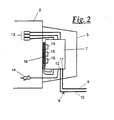
- FIG. 2 makes it clear, it can be in the data line 6, via which the relevant engine 1 with the central Control unit 8 is connected to act a simple two-wire line, for which one of the two lines 9, an input 11 and for the other line 10, an output 12 is provided on the motor switching stage 7.
- the data line 6 is a two-wire bus system, which is connected to a bus master, which is integrated in the central control unit 8.
- the data line 6 can bidirectionally connect one or more of the motors 1 to the central control unit 8 via the bus system in order to be able to provide data feedback to the control unit.
- the control unit 8 may have data memory, from which, if necessary, the operating states of one or more monitored motors 1 can be retrieved.
- FIG. 2 further shows the motor windings 13, which are represented schematically by their resistances and are connected in the motor switching stage 7 with the power stage.
- Their electronic load relays have semiconductor components 15, which heat up due to the current load and are accordingly equipped with cooling elements, such as ribbed plates or the like.
- the semiconductor components 15 are placed with their cooling elements on a Peltier element 16, which is arranged on the motor housing 2.
- the Peltier element 16 is supplied with a current which is proportional to the motor current, whereby a corresponding cooling power acting on the semiconductor components 15 is available.
- thermocouple 14 of which several in the motor winding 13 may be involved.
- Each of these thermocouples 14 is connected in the motor switching stage 7 with the integrated Termistortime, which results in a very short conduction path between the temperature measuring and the Termistoresti whose resistance is practically negligible.
Landscapes
- Engineering & Computer Science (AREA)
- Power Engineering (AREA)
- Microelectronics & Electronic Packaging (AREA)
- Control Of Multiple Motors (AREA)
Claims (2)
- Moteur électrique alimenté par le secteur avec un carter de moteur (2) et une boîte de raccord du moteur (3) portée par celui-ci, dans laquelle sont raccordés au moins une conduite d'alimentation en énergie (4) ainsi qu'une ligne de transmission de données (6) pour la communication de l'état de fonctionnement du moteur, de plus avec un étage de commutation du moteur, pour commutation étoile-triangle, démarrage en douceur et / ou interruption de surcharge, qui est installé dans la boîte de raccord du moteur (3), les signaux de commande pour l'étage de commutation du moteur (7) étant en plus transmis par la ligne de transmission de données (6), et la conduite d'alimentation en énergie (4) étant reliée directement au secteur,
caractérisé en ce que
l'étage de commutation du moteur (7) présente des éléments à semi-conducteurs (15), entre lesquels et le carter du moteur (2) est agencé au moins un élément Peltier (16) qui est alimenté avec un courant proportionnel au courant du moteur. - Moteur électrique alimenté par le secteur selon la revendication 1,
caractérisé en ce que,
dans les bobinages (13) du moteur (1), sont insérés des thermo-éléments (14) pour le contrôle de la température, lesquels sont reliés à l'étage de commutation du moteur (7) dans la boîte de raccord du moteur (3).
Applications Claiming Priority (2)
| Application Number | Priority Date | Filing Date | Title |
|---|---|---|---|
| DE19704801A DE19704801C2 (de) | 1997-02-08 | 1997-02-08 | Netzbetriebener Elektromotor |
| DE19704801 | 1997-02-08 |
Publications (3)
| Publication Number | Publication Date |
|---|---|
| EP0858146A2 EP0858146A2 (fr) | 1998-08-12 |
| EP0858146A3 EP0858146A3 (fr) | 1999-11-10 |
| EP0858146B1 true EP0858146B1 (fr) | 2008-04-16 |
Family
ID=7819692
Family Applications (1)
| Application Number | Title | Priority Date | Filing Date |
|---|---|---|---|
| EP98102077A Expired - Lifetime EP0858146B1 (fr) | 1997-02-08 | 1998-02-06 | Moteur électrique alimentée par le secteur |
Country Status (2)
| Country | Link |
|---|---|
| EP (1) | EP0858146B1 (fr) |
| DE (2) | DE19704801C2 (fr) |
Families Citing this family (10)
| Publication number | Priority date | Publication date | Assignee | Title |
|---|---|---|---|---|
| DE19957064B4 (de) | 1999-11-26 | 2020-06-18 | Sew-Eurodrive Gmbh & Co Kg | Deckel |
| DE10005995B4 (de) * | 2000-02-10 | 2004-10-21 | Sew-Eurodrive Gmbh & Co. Kg | Verfahren zum Beschleunigen einer Anlage und eine Vorrichtung zur Durchführung des Verfahrens |
| DE20003532U1 (de) | 2000-02-25 | 2000-07-20 | Schmitt, Wolfgang, Dipl.-Ing. (Fh), 94060 Pocking | Digitale Leistungseinheit in Modulbauweise |
| DE10010290A1 (de) * | 2000-03-02 | 2001-09-06 | Abb Patent Gmbh | Elektronisches Überlastrelais |
| DE10062912A1 (de) * | 2000-12-16 | 2002-07-11 | Buhler Motor Gmbh | Adressierung eines busgesteuerten Stellantriebs |
| DE10062918A1 (de) * | 2000-12-16 | 2002-06-20 | Buhler Motor Gmbh | Busgesteuerter Stellantrieb |
| DE10108548A1 (de) | 2001-02-22 | 2002-09-26 | Siemens Ag | Stellvorrichtung für einen Motor |
| DE102007034915B4 (de) * | 2007-07-24 | 2011-01-05 | Sew-Eurodrive Gmbh & Co. Kg | Motoranschlusskasten und Umrichtermotor |
| DE102009031466B4 (de) | 2009-07-01 | 2023-06-29 | Sew-Eurodrive Gmbh & Co Kg | Elektromotor und Anlage mit Elektromotoren |
| DE202019100295U1 (de) * | 2019-01-18 | 2020-04-23 | Brose Fahrzeugteile SE & Co. Kommanditgesellschaft, Würzburg | Antriebseinrichtung für einen Kühlerlüfter |
Family Cites Families (6)
| Publication number | Priority date | Publication date | Assignee | Title |
|---|---|---|---|---|
| DE7117076U (de) * | 1971-04-28 | 1971-07-22 | Siemens Ag | Nutthermometer fuer elektrische maschinen |
| DE3332515A1 (de) * | 1983-09-09 | 1985-03-28 | Brown, Boveri & Cie Ag, 6800 Mannheim | Elektrische maschine |
| US4602872A (en) * | 1985-02-05 | 1986-07-29 | Westinghouse Electric Corp. | Temperature monitoring system for an electric generator |
| US4825133A (en) * | 1986-08-05 | 1989-04-25 | Oki Electric Industry Co., Ltd. | Electromechanical actuator control system |
| US5040381A (en) * | 1990-04-19 | 1991-08-20 | Prime Computer, Inc. | Apparatus for cooling circuits |
| DE29606996U1 (de) * | 1996-04-20 | 1996-07-04 | Graesslin Kg | Elektromotorischer Stellantrieb |
-
1997
- 1997-02-08 DE DE19704801A patent/DE19704801C2/de not_active Expired - Fee Related
-
1998
- 1998-02-06 DE DE59814216T patent/DE59814216D1/de not_active Expired - Lifetime
- 1998-02-06 EP EP98102077A patent/EP0858146B1/fr not_active Expired - Lifetime
Also Published As
| Publication number | Publication date |
|---|---|
| DE19704801C2 (de) | 1999-04-29 |
| EP0858146A2 (fr) | 1998-08-12 |
| DE19704801A1 (de) | 1998-08-20 |
| DE59814216D1 (de) | 2008-05-29 |
| EP0858146A3 (fr) | 1999-11-10 |
Similar Documents
| Publication | Publication Date | Title |
|---|---|---|
| DE60206265T3 (de) | Programmierbare steuereinheit zur ferngesteuerten regelung der eingangsleistung eines verbrauchers vermittels schalter sowie verfahren dazu | |
| EP1530405B1 (fr) | Dispositif de chauffage électrique, particulièrement pour véhicules automobiles. | |
| DE69606898T2 (de) | Schnittstellenmodul für einen Feldbus und ein elektrisches Steuer- und Schutzgerät eines Elektromotors | |
| EP0858146B1 (fr) | Moteur électrique alimentée par le secteur | |
| EP1104080A2 (fr) | Couvercle pour un boítier de connection d'un moteur électrique | |
| DE19739780B4 (de) | Drehstrommotor | |
| EP0956220A1 (fr) | Agencement de commutateurs pour appareils de commande electriques | |
| EP1362405B1 (fr) | Dispositif de reglage pour un moteur | |
| WO1999018634A1 (fr) | Armoire electrique | |
| EP2184830B1 (fr) | Dispositif de surveillance de la température d'un enroulement de courant multiphasé d'une machine électrique | |
| EP3440976B1 (fr) | Appareil électroménager entraîné par un accumulateur ainsi que procédé de fonctionnement d'un appareil électroménager | |
| DE19719232A1 (de) | Automatisierungssystem für Heizungs-, Klima- und Lüftungsanlagen | |
| DE10147472A1 (de) | Stromrichtergerät | |
| DE3029851C2 (de) | Schaltungsanordnung zur signaltechnisch sicheren Ansteuerung eines Stromverbrauchers | |
| DE102007043872A1 (de) | Antriebsanordnung | |
| DE19713448A1 (de) | Einrichtung zur Schutzabschaltung einer elektrischen Maschine bei Übertemperatur | |
| DE102017210521A1 (de) | Baueinheit zum Bereitstellen von Ausgangsspannungen | |
| EP0843243A2 (fr) | Système de positionnement avec une alimentation électronique intégrée et une commande de position intégrée à technologie de connexion et répartition des composants optimalisées | |
| DE19817398C2 (de) | Elektrische Weichenheizungssteuereinrichtung | |
| EP4416472B1 (fr) | Procédé de fonctionnement d'un appareillage de commutation et appareillage de commutation | |
| EP2775080B1 (fr) | Dispositif de commande pour un entraînement de fenêtre ou analogue | |
| DE112004002933B4 (de) | Vorrichtung zum Steuern des Energieflusses zwischen einem Energieversorgungsnetz und einer daran angeschlossenen elektrischen Einrichtung | |
| WO2001004710A1 (fr) | Module de commande d'un mecanisme d'entrainement | |
| DE102022204949A1 (de) | Ansteuerschaltung für ein Heizungssystem | |
| DE19758915B4 (de) | Elektrische Heizeinrichtung für ein Kraftfahrzeug |
Legal Events
| Date | Code | Title | Description |
|---|---|---|---|
| PUAI | Public reference made under article 153(3) epc to a published international application that has entered the european phase |
Free format text: ORIGINAL CODE: 0009012 |
|
| AK | Designated contracting states |
Kind code of ref document: A2 Designated state(s): DE FR GB IT |
|
| AX | Request for extension of the european patent |
Free format text: AL;LT;LV;MK;RO;SI |
|
| PUAL | Search report despatched |
Free format text: ORIGINAL CODE: 0009013 |
|
| AK | Designated contracting states |
Kind code of ref document: A3 Designated state(s): AT BE CH DE DK ES FI FR GB GR IE IT LI LU MC NL PT SE |
|
| AX | Request for extension of the european patent |
Free format text: AL;LT;LV;MK;RO;SI |
|
| 17P | Request for examination filed |
Effective date: 20000309 |
|
| AKX | Designation fees paid |
Free format text: DE FR GB IT |
|
| RAP1 | Party data changed (applicant data changed or rights of an application transferred) |
Owner name: PHOENIX CONTACT GMBH & CO. KG |
|
| 17Q | First examination report despatched |
Effective date: 20030730 |
|
| GRAP | Despatch of communication of intention to grant a patent |
Free format text: ORIGINAL CODE: EPIDOSNIGR1 |
|
| GRAS | Grant fee paid |
Free format text: ORIGINAL CODE: EPIDOSNIGR3 |
|
| GRAA | (expected) grant |
Free format text: ORIGINAL CODE: 0009210 |
|
| AK | Designated contracting states |
Kind code of ref document: B1 Designated state(s): DE FR GB IT |
|
| REF | Corresponds to: |
Ref document number: 59814216 Country of ref document: DE Date of ref document: 20080529 Kind code of ref document: P |
|
| ET | Fr: translation filed | ||
| PLBE | No opposition filed within time limit |
Free format text: ORIGINAL CODE: 0009261 |
|
| STAA | Information on the status of an ep patent application or granted ep patent |
Free format text: STATUS: NO OPPOSITION FILED WITHIN TIME LIMIT |
|
| 26N | No opposition filed |
Effective date: 20090119 |
|
| PGFP | Annual fee paid to national office [announced via postgrant information from national office to epo] |
Ref country code: IT Payment date: 20120224 Year of fee payment: 15 |
|
| PGFP | Annual fee paid to national office [announced via postgrant information from national office to epo] |
Ref country code: GB Payment date: 20130221 Year of fee payment: 16 Ref country code: FR Payment date: 20130314 Year of fee payment: 16 Ref country code: DE Payment date: 20130205 Year of fee payment: 16 |
|
| REG | Reference to a national code |
Ref country code: DE Ref legal event code: R119 Ref document number: 59814216 Country of ref document: DE |
|
| GBPC | Gb: european patent ceased through non-payment of renewal fee |
Effective date: 20140206 |
|
| REG | Reference to a national code |
Ref country code: FR Ref legal event code: ST Effective date: 20141031 |
|
| REG | Reference to a national code |
Ref country code: DE Ref legal event code: R119 Ref document number: 59814216 Country of ref document: DE Effective date: 20140902 |
|
| PG25 | Lapsed in a contracting state [announced via postgrant information from national office to epo] |
Ref country code: FR Free format text: LAPSE BECAUSE OF NON-PAYMENT OF DUE FEES Effective date: 20140228 Ref country code: GB Free format text: LAPSE BECAUSE OF NON-PAYMENT OF DUE FEES Effective date: 20140206 Ref country code: DE Free format text: LAPSE BECAUSE OF NON-PAYMENT OF DUE FEES Effective date: 20140902 |
|
| PG25 | Lapsed in a contracting state [announced via postgrant information from national office to epo] |
Ref country code: IT Free format text: LAPSE BECAUSE OF NON-PAYMENT OF DUE FEES Effective date: 20140206 |