EP0858155A1 - Procédé de régulation d'une machine tournante, système d'asservissement pour mettre en oeuvre ledit procédé, et machine tournante pourvue d'un tel système - Google Patents
Procédé de régulation d'une machine tournante, système d'asservissement pour mettre en oeuvre ledit procédé, et machine tournante pourvue d'un tel système Download PDFInfo
- Publication number
- EP0858155A1 EP0858155A1 EP98400187A EP98400187A EP0858155A1 EP 0858155 A1 EP0858155 A1 EP 0858155A1 EP 98400187 A EP98400187 A EP 98400187A EP 98400187 A EP98400187 A EP 98400187A EP 0858155 A1 EP0858155 A1 EP 0858155A1
- Authority
- EP
- European Patent Office
- Prior art keywords
- state
- computer
- adj
- ref
- stator
- Prior art date
- Legal status (The legal status is an assumption and is not a legal conclusion. Google has not performed a legal analysis and makes no representation as to the accuracy of the status listed.)
- Withdrawn
Links
- 238000000034 method Methods 0.000 title claims abstract description 67
- 230000033228 biological regulation Effects 0.000 title description 7
- 230000004907 flux Effects 0.000 claims abstract description 71
- 239000013598 vector Substances 0.000 claims abstract description 70
- 238000005070 sampling Methods 0.000 claims abstract description 66
- 238000011217 control strategy Methods 0.000 claims description 23
- 230000007423 decrease Effects 0.000 claims description 7
- FGUUSXIOTUKUDN-IBGZPJMESA-N C1(=CC=CC=C1)N1C2=C(NC([C@H](C1)NC=1OC(=NN=1)C1=CC=CC=C1)=O)C=CC=C2 Chemical compound C1(=CC=CC=C1)N1C2=C(NC([C@H](C1)NC=1OC(=NN=1)C1=CC=CC=C1)=O)C=CC=C2 FGUUSXIOTUKUDN-IBGZPJMESA-N 0.000 claims description 6
- 230000001105 regulatory effect Effects 0.000 claims description 6
- 230000001360 synchronised effect Effects 0.000 claims description 6
- 230000003247 decreasing effect Effects 0.000 claims description 3
- 230000008569 process Effects 0.000 description 11
- 241000287107 Passer Species 0.000 description 4
- 230000008901 benefit Effects 0.000 description 4
- 230000004044 response Effects 0.000 description 3
- 230000007704 transition Effects 0.000 description 3
- 230000001276 controlling effect Effects 0.000 description 2
- 238000012423 maintenance Methods 0.000 description 2
- 230000008859 change Effects 0.000 description 1
- 230000001939 inductive effect Effects 0.000 description 1
- 238000004886 process control Methods 0.000 description 1
Images


Classifications
-
- H—ELECTRICITY
- H02—GENERATION; CONVERSION OR DISTRIBUTION OF ELECTRIC POWER
- H02P—CONTROL OR REGULATION OF ELECTRIC MOTORS, ELECTRIC GENERATORS OR DYNAMO-ELECTRIC CONVERTERS; CONTROLLING TRANSFORMERS, REACTORS OR CHOKE COILS
- H02P21/00—Arrangements or methods for the control of electric machines by vector control, e.g. by control of field orientation
- H02P21/12—Stator flux based control involving the use of rotor position or rotor speed sensors
-
- H—ELECTRICITY
- H02—GENERATION; CONVERSION OR DISTRIBUTION OF ELECTRIC POWER
- H02M—APPARATUS FOR CONVERSION BETWEEN AC AND AC, BETWEEN AC AND DC, OR BETWEEN DC AND DC, AND FOR USE WITH MAINS OR SIMILAR POWER SUPPLY SYSTEMS; CONVERSION OF DC OR AC INPUT POWER INTO SURGE OUTPUT POWER; CONTROL OR REGULATION THEREOF
- H02M7/00—Conversion of AC power input into DC power output; Conversion of DC power input into AC power output
- H02M7/42—Conversion of DC power input into AC power output without possibility of reversal
- H02M7/44—Conversion of DC power input into AC power output without possibility of reversal by static converters
- H02M7/48—Conversion of DC power input into AC power output without possibility of reversal by static converters using discharge tubes with control electrode or semiconductor devices with control electrode
- H02M7/53—Conversion of DC power input into AC power output without possibility of reversal by static converters using discharge tubes with control electrode or semiconductor devices with control electrode using devices of a triode or transistor type requiring continuous application of a control signal
- H02M7/537—Conversion of DC power input into AC power output without possibility of reversal by static converters using discharge tubes with control electrode or semiconductor devices with control electrode using devices of a triode or transistor type requiring continuous application of a control signal using semiconductor devices only, e.g. single switched pulse inverters
- H02M7/5387—Conversion of DC power input into AC power output without possibility of reversal by static converters using discharge tubes with control electrode or semiconductor devices with control electrode using devices of a triode or transistor type requiring continuous application of a control signal using semiconductor devices only, e.g. single switched pulse inverters in a bridge configuration
- H02M7/53871—Conversion of DC power input into AC power output without possibility of reversal by static converters using discharge tubes with control electrode or semiconductor devices with control electrode using devices of a triode or transistor type requiring continuous application of a control signal using semiconductor devices only, e.g. single switched pulse inverters in a bridge configuration with automatic control of output voltage or current
- H02M7/53875—Conversion of DC power input into AC power output without possibility of reversal by static converters using discharge tubes with control electrode or semiconductor devices with control electrode using devices of a triode or transistor type requiring continuous application of a control signal using semiconductor devices only, e.g. single switched pulse inverters in a bridge configuration with automatic control of output voltage or current with analogue control of three-phase output
Definitions
- the invention relates to a method for regulating a rotating machine, a servo system to put implementing said method, and a rotary machine provided of such a system.
- the present invention relates to a electromagnetic torque and flux regulation process stator of an asynchronous rotating machine having a high dynamic level from low speeds to high speeds.
- US-A-4678248 relates to a method of regulation where the control quantities are the electromagnetic torque and the stator flow.
- This method involves vector modeling of the machine and the voltage inverter.
- the electromagnetic torque is a function of the angle existing between the rotating rotor flux vector and the stator flux rotating vector and the modules of these flux vectors.
- the stator voltage vector V s is delivered by a three-phase voltage inverter each phase comprising a two-state switch (SP2LL: Single Pole 2 Logic Levels / single pole with 2 logic levels). Therefore, the stator voltage vector V s can take 8 states V 1 ... V 8 (2 3 ), including two V 1 , V 8 of zero amplitude (zero states) in the fixed stator frame ( ⁇ , ⁇ ), depending on the combination of the three SP2LLs of the inverter.
- SP2LL Single Pole 2 Logic Levels / single pole with 2 logic levels. Therefore, the stator voltage vector V s can take 8 states V 1 ... V 8 (2 3 ), including two V 1 , V 8 of zero amplitude (zero states) in the fixed stator frame ( ⁇ , ⁇ ), depending on the combination of the three SP2LLs of the inverter.
- the so-called DTC (Direct Torque Control) system is based, in the stator frame ( ⁇ , ⁇ ), on the maintenance of the module
- DTC Direct Torque Control
- the control of the stator flux vector ⁇ S is ensured by means of a finite table.
- the response dynamics of the above solution is very bad.
- the response time of the step negative is around four times the response time a positive step of the same magnitude.
- the proposed technique dedicates the control of the stator flow (maintenance of the module of the stator flow in the hysteresis band) to Torque control.
- the configurations in which a control of the stator flow is concomitant with the control of the torque ⁇ em are not provided.
- EP-A-0674381 relates to a method for controlling a asynchronous rotating machine taking over for a range of speeds the previous DTC method by adding a hysteresis on the couple.
- the method provides two additional operating modes, one for low speeds and the other for high speeds.
- the operating mode at low speeds is based on the imposition of a switching frequency of the inverter.
- the high speed operating mode is full wave mode.
- One of the aims of the present invention is to propose a method of regulation in electromagnetic torque and in stator flow of an asynchronous rotating machine in which the switching times of the inverter are predicted by computation, and performed asynchronously with the moments of sampling or calculation.
- the sampling frequencies no longer need to be as high as in the prior art, and are reduced to frequencies used as standard in known real-time devices (between 2kHz and 5kHz)
- Another object of the present invention is to provide a method of regulation in electromagnetic torque and in stator flow of an asynchronous rotating machine in which regulates the electromagnetic torque and the flux stator can be concomitant.
- Another object of the present invention is to provide a method of regulation in electromagnetic torque and in stator flow of an asynchronous rotating machine in which the transition to full wave mode requires no change of strategy.
- the invention relates to a method for regulating a rotary machine with n phases supplied with alternating current by means of a voltage inverter comprising n SPmLL defining m n states of the stator phase voltage vector, said machine being subject to electromagnetic torque ⁇ and stator flux
- the computer performing the calculations in a three-dimensional orthogonal calculation reference system comprising the stator plane ( ⁇ s ⁇ , ⁇ s ⁇ ) of the stator flow ⁇ S and an axis, perpendicular to said stator plane ( ⁇ s ⁇ , ⁇ s ⁇ ), representing the couple ⁇ , the instructions ⁇ ref ,
- the control strategy is based on the application of a SOCMLI cycle such that the calculator searches for the existence of a single triplet of states (V 0 , V i , V adj ) i ⁇ ⁇ 2 ... m n -1 ⁇ of the voltage vector constituting a succession of three states, comprising a starting state V i , one of the two states V adj adjacent to V i and a null state (V 0 ), of which the respective application times dt i , dt adj , dt 0 are positive and such that their sum is equal to half of the switching period T d of the inverter.
- step c) the computer solves the following system: where ⁇ , is a parameter defining the position of the point D on a tangent to the circle ⁇ cal in D '.
- step f) the calculator solves the following system by the method of least squares:
- step i) the computer calculates for the current point C '( ⁇ s ⁇ c , ⁇ s ⁇ c , ⁇ c ) the time remaining dt 0r of application of the state V 0 by solving by the method of least squares the following system:
- step d) the computer can provide for switching from state V i to the other adjacent state of V i in order to crop the trajectory from point B 'to the circle ⁇ cal .
- the computer searches for a succession of two states (V i , V adj ) different from a zero state allowing the point to be brought closer together A ( ⁇ s ⁇ , ⁇ s ⁇ , ⁇ ) of the circle ⁇ ref in the time interval 1 ⁇ 2T d .
- the computer performing the calculations in a reference frame of orthogonal three-dimensional calculation comprising the stator plane ( ⁇ s ⁇ , ⁇ s ⁇ ) of the stator flux ⁇ S and an axis, perpendicular to said stator plane ( ⁇ s ⁇ , ⁇ s ⁇ ) , representing the couple ⁇ , the instructions ⁇ ref ,
- the number of predetermined positions authorized by stator flow turn is finite and a function of a range of rotation speed of the rotating machine.
- the control strategy is such that the computer knows a unique triplet of states (V 0 , V i , V adj ) i ⁇ ⁇ 2 ... m n -1 ⁇ of the voltage vector constituting a succession of three states, comprising a starting state V i , one of the two states V adj adjacent to V i and a zero state (V 0 ), whose respective application times dt i , dt adj , dt 0 are positive, said triplet making it possible to join the circle ⁇ cal at a known point D.
- step c the computer solves the following system:
- step f) the computer solves the following system: where ⁇ is a parameter defining the predictable final position of the current point B 'on a line contained in the stator plane, passing through the torque axis and parallel to the predetermined position of the stator flux vector which must be reached.
- the transition to full wave results from the fact that the time dt 0 of application of the zero state is a decreasing function of the speed of rotation of the rotary machine, and is equal to zero beyond a predetermined value of the rotation speed of the rotating machine.
- the invention also relates to a servo system to implement the method described above.
- the invention finally relates to a rotating machine provided with such a servo system.
- a first advantage of the present invention results desynchronization of the sampling instants and calculation of switching instants. This allows a significant increase in the sampling period and so in particular to apply the process with devices standard sampling.
- Another advantage of the present invention results from the made of the explicit presence of the concept of time which allows to take into account in a reliable way the constraints switching frequencies and minimum conduction time inherent in power converters.
- Another advantage of the present invention is a optimal torque dynamics even at low speed.
- the invention relates to a method for regulating a rotating machine 1 with n phases supplied with alternating current via a voltage inverter 3 comprising n switches 4 with m positions (SPmLL: Single Pole m Logic Levels / single pole at m logical levels). defining m n states V i i ⁇ ⁇ 1, .., m n ⁇ of the stator phase voltage vector V S.
- SPmLL Single Pole m Logic Levels / single pole at m logical levels
- Machine 1 is controlled by an electromagnetic couple ⁇ and a stator flux
- the servo system 5 comprises a set of sensors 7, 8, 9 whose sensed values are transmitted to an observer-sampler 10.
- the outputs of the observer 10, sampled according to a given sampling period T e , are injected into a computer 13.
- the computer 13 restoring at the output signals of control 6 of the SPmLL 4 of the voltage inverter 3.
- the outputs of the observer 10 are values representative of the couple ⁇ and of the stator flux
- the computer In addition to the sampled outputs, the computer also receives as input the values representative of the setpoints ⁇ ref and
- the method described above therefore makes it possible to predict, by calculation, the switching times to come and perform the switching at the calculated times regardless of the sampling or calculation instants.
- the computer performs the calculations in a reference frame of orthogonal three-dimensional calculation comprising the stator plane ( ⁇ s ⁇ , ⁇ s ⁇ ) of the stator flux ⁇ S and an axis, perpendicular to the stator plane ( ⁇ s ⁇ , ⁇ s ⁇ ), representing the couple ⁇ .
- ref are represented by a circle ⁇ ref contained in a plane parallel to the stator plane ( ⁇ s ⁇ , ⁇ s ⁇ ), centered on the perpendicular axis, having a radius of
- the process control strategies are strategies in which the succession of n states of the voltage vector is calculated so that the point A ( ⁇ s ⁇ , ⁇ s ⁇ , ⁇ ) joins any point D of a circle ⁇ cal , centered on said perpendicular axis, having a radius of
- the calculator calculates the equation of the circle ⁇ cal so that over the duration of application of the succession of n states, the average torque et and the stator flux
- the rotating machine is a three-phase machine, and the inverter includes SP2LL.
- the process can be applied with an n phases and SPmLL.
- the method will apply a triplet (V 0 , V i , V adj ) i ⁇ ⁇ 2 ... m n -1 ⁇ consisting of a succession of three states, comprising a state of departure V i , one of the two states adj adj adjacent to V i and a null state V 0 .
- the method must therefore define the respective application times dt i , dt adj , dt 0 of the triplet.
- the adjustment of these three durations allows three degrees of freedom.
- the control according to which at the end of application of the triplet the couple and the stator flux must be found on ⁇ cal constrains only two degrees of freedom.
- An additional constraint must therefore be applied in order to be able to determine the three application times.
- the method according to the invention proposes two constraints each determining a strategy for different control:
- the so-called synchronous control strategy in which the additional constraint is a constraint imposing a position of the rotating stator flow vector at the end application of the triplet regardless of the time elapsed for the application of the triplet.
- the control strategy is based on the application of a cycle such that the calculator searches for the existence of a single triplet of states (V 0 , V i , V adj ) i ⁇ ⁇ 2 ... m n - 1 ⁇ of the voltage vector constituting a succession of three states, comprising a starting state V i , one of the two states V adj adjacent to V i and a zero state V 0 , whose respective application times dt i , dt adj , dt 0 are positive and such that their sum is equal to half the switching period T d of the inverter.
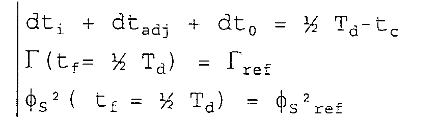
- dt i + dt adj + dt 0 1 ⁇ 2 T d
- the computer calculates for the current point A 'the application times by solving the system of three equations with three unknowns the system of three equations with three unknowns above is linearized by replacing the presumed point of arrival D 'by a plane G tangent in D' to the circle ⁇ cal .
- ⁇ is a parameter defining the position of point D on a tanqente to the circle ⁇ cal in D 'such that D not being taxed and or according to the state V index of the stator phase vector V S it is understood that for the calculation of the directional derivatives, the model of the rotary machine must have been previously introduced into the computer.
- (SA1) therefore makes it possible, at each sampling instant on the segment AB, to provide the three duration of application dt ir , dt adj , dt 0 .
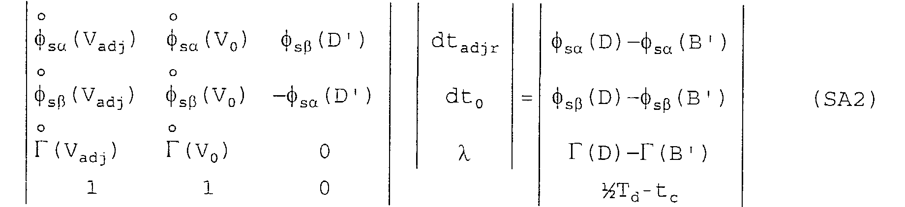
- step f the calculator solves the following system by the method of least squares (step f)):
- SA2 provides the application durations dt adjr and dt 0 .
- step d) the computer can provide for switching from state V i to the other adjacent state of V i in order to crop the trajectory from point B 'to the circle ⁇ ref . This may be necessary when, during the flow of dt i , the setpoints have been significantly modified. Therefore, the computer can determine that the application of the other state adjacent to V i is more optimal. The other state adjacent to V i will then be applied for the time dt adj expected.
- the computer searches for a succession of two adjacent states (V i , V adj ) different from a null state allowing the point A ( ⁇ s ⁇ , ⁇ s ⁇ , ⁇ ) to be brought closer to the circle ⁇ ref in the time interval 1 ⁇ 2T d .
- the number of predetermined positions authorized by stator flow turn is finite and a function of a range of rotation speed of the rotating machine.
- the control strategy is such that the computer knows a single triplet of states (V 0 , V i , V adj ) i ⁇ ⁇ 2 ... m n - 1 ⁇ of the voltage vector constituting a succession of three states, comprising a starting state V i , one of the two states V adj adjacent to V i and a zero state (V 0 ), whose respective application times dt i , dt adj , dt 0 are positive, the triplet making it possible to join the circle ⁇ cal at a desired point D.
- the computer calculates, for the current point A ', the application times by solving the system where ⁇ is the angle fixed to arrive at the point D imposed a priori.
- step c the computer solves the following linear system: with D imposed a priori.
- step f) the computer solves the following system: where ⁇ is a parameter defining the predictable final position of the current point B 'on a line contained in the stator plane, passing through the torque axis and parallel to the predetermined position of the stator flux vector which must be reached.
- the time dt 0 of application of the zero state is a decreasing function of the speed of rotation of the rotating machine, and equal to zero beyond a predetermined value of the speed of rotation of the rotating machine.
- a applied stator flux corrector function of difference between the instantaneous torque and the torque of instructions.
- the corrector decreases the flow norm stator
- the corrector increases the flow norm stator.
- the invention also relates to a servo system to implement the method described above.
- the invention finally relates to a rotating machine provided with such a servo system.
- the invention is not limited to the mode of implementation or realization described but it is susceptible of numerous variants accessible to the man of the profession without departing from the invention.
- the number of phases, the number of levels logic of each unique skiff, the calculation space, the calculation systems can vary without departing from the invention.
Landscapes
- Engineering & Computer Science (AREA)
- Power Engineering (AREA)
- Control Of Ac Motors In General (AREA)
- Control Of Position Or Direction (AREA)
Abstract
Description

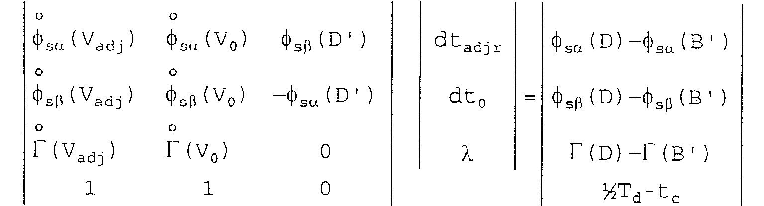
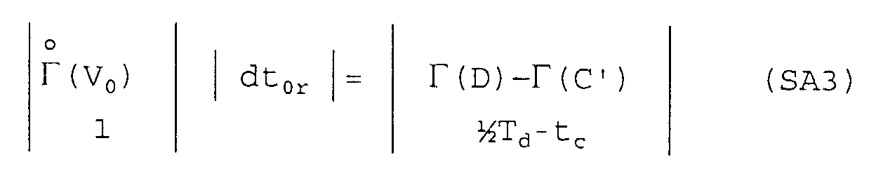
le calculateur calcule pour le point courant C'(sαc, sβc, Γc) le temps restant dt0r d'application de l'état V0 en résolvant par la méthode des moindres carrés le système suivant :


le calculateur calcule pour le point courant C'(sαc, sβc, Γc) le temps restant dt0r d'application de l'état V0 en résolvant le système suivant :

- la figure 1 est une représentation schématique d'un dispositif selon l'invention.
- les figures 2 et 3 sont des illustrations schématiques d'un exemple de calcul dans le mode asynchrone selon l'invention.
- les figures 4 et 5 sont des illustrations schématiques d'un exemple de calcul dans le mode synchrone selon l'invention.
- la figure 6 est une représentation schématique d'un exemple de correction en mode pleine onde selon l'invention.
la stratégie de contrôle est basée sur l'application d'un cycle tel que le calculateur recherche l'existence d'une triplette unique d'états (V0, Vi, Vadj) i∈{2...mn-1} du vecteur tension constituant une succession de trois états, comprenant un état de départ Vi, un des deux états Vadj adjacent à Vi et un état nul V0, dont les temps d'application respectifs dti, dtadj, dt0 sont positifs et tels que leur somme soit égale à la moitié de la période de découpage Td de l'onduleur.


et où

on comprend que pour le calcul des dérivées directionnelles, le modèle de la machine tournante devra avoir été préalablement introduit dans le calculateur.



Claims (18)
- Procédé de régulation d'une machine tournante à n phases alimentée en courant alternatif par l'intermédiaire d'un onduleur de tension comprenant n SPmLL définissant mn états du vecteur tension de phase stator, ladite machine étant asservie en couple électromagnétique Γ et en flux statorique |S| à des consignes Γref, |S|ref par un système d'asservissement pouvant suivre différentes stratégies de contrôle, chaque stratégie ayant des conditions d'application, ledit système d'asservissement comprenant un ensemble de capteurs dont les valeurs captées sont transmises à un observateur-échantillonneur, les sorties de l'observateur, échantillonnées selon une période d'échantillonnage donnée Te, étant injectées dans un calculateur, ledit calculateur restituant en sortie des signaux de commande des SPmLL de l'onduleur de tension,
caractérisé en ce que,le calculateur calcule, en fonction des conditions d'application de la stratégie de contrôle utilisée, d'une part une succession de n états du vecteur tension de phase pour rapprocher le couple Γ et le flux |S| des consignes Γref, |S|ref, par commutation successive desdits n états de la succession, et d'autre part le temps d'application dtk k ∈ {1,...,n} de chacun desdits n états de la succession,à chaque échantillonnage, le calculateur calcule le temps d'application restant de l'état en cours et les temps d'application mis à jour des états futurs du vecteur de phase, etde façon asynchrone avec les instants d'échantillonnage et de calcul, à la fin du temps d'application de l'état en cours, le calculateur envoi des signaux de commande des SPmLL pour commuter de l'état en cours vers l'état suivant. - Procédé de régulation selon la revendication 1 le calculateur effectuant les calculs dans un référentiel de calcul tridimensionnel orthogonal comprenant le plan statorique (sα, sβ) du flux stator S et un axe, perpendiculaire audit plan statorique (sα, sβ), représentant le couple Γ, les consignes Γref, |S|ref, étant représentées par un cercle ηref contenu dans un plan parallèle au plan statorique (sα, sβ), centré sur ledit axe perpendiculaire, ayant un rayon de |S|ref et interceptant ledit axe perpendiculaire en Γref, les valeurs Γ, S fournies par la machine tournante, étant représentées par un point A (sα,sβ, Γ) sur un cercle η contenu dans un plan parallèle au plan statorique (sα, sβ), centré sur ledit axe perpendiculaire, ayant un rayon de |S| et interceptant ledit axe perpendiculaire en Γ;
le procédé étant caractérisé en ce que la stratégie de contrôle est une stratégie asynchrone avec la fréquence de rotation de la machine tournante dans laquelle la succession de n états du vecteur tension est calculée pour que le point A (sα, sβ , Γ) rallie un point D quelconque d'un cercle ηcal, centré sur ledit axe perpendiculaire, ayant un rayon de |S|cal et interceptant ledit axe perpendiculaire en Γcal par application successive des n états, dans un temps donné prédéterminé, ledit calculateur calculant l'équation du cercle ηcal pour que sur la durée d'application de la succession, le couple Γ moyen et le flux statorique |S| moyen générés soient sensiblement égaux respectivement aux consignes Γref, |S|ref. - Procédé de régulation selon la revendication 2 caractérisé en ce que, n étant égal à trois, la stratégie de contrôle est basée sur l'application d'un cycle SOCMLI telle que le calculateur recherche l'existence d'une triplette unique d'états (V0, Vi, Vadj) i∈{2...mn-1} du vecteur tension constituant une succession de trois états, comprenant un état de départ Vi, un des deux états Vadj adjacent à Vi et un état nul (V0), dont les temps d'application respectifs dti, dtadj, dt0 sont positifs et tels que leur somme soit égale à la moitié de la période de découpage Td de l'onduleur.
- Procédé de régulation selon la revendication 3 caractérisé en ce que,le calculateur traitant la nouvelle triplette (V'0, V'i, V'adj) selon les étapes c) à k).a) le calculateur cherche la triplette unique (V0, Vi, Vadj) i∈{2...mn-1}, et calcule un point d'arrivée présumé D' sur le cercle ηcal, puisb) il envoi des signaux de commande des SPmLL pour commuter dans l'état Vi, puis,c) à chaque échantillonnage, le calculateur calcule, pour le point courant A'(sαc, sβc, Γc), le temps restant dtir d'application de l'état Vi et les temps dtadj et dt0 mis à jour des états futurs Vadj et V0, puis,d) lorsque dtir≤Te, le calculateur prévoit l'instant de commutation de l'état Vi vers l'état Vadj, puis,e) de façon asynchrone avec les instants d'échantillonnage et de calcul, lorsque l'instant de commutation arrive, le calculateur envoi des signaux de commande des SPmLL pour commuter dans l'état Vadj, puis,f) à chaque échantillonnage, le calculateur calcule, pour le point courant B'(sαc, sβc, Γc), le temps restant dtadjr d'application de l'état Vadj et le temps dt0 mis à jour de l'état futur V0, puis,g) lorsque dtadjr≤Te, le calculateur prévoit l'instant de commutation de l'état Vadj vers l'état V0, puis,h) de façon asynchrone avec les instants d'échantillonnage et de calcul, lorsque l'instant de commutation arrive, le calculateur envoi des signaux de commande des SPmLL pour commuter dans l'état V0, puis,i) à chaque échantillonnage, le calculateur calcule pour le point courant C'(sαc, sβc, Γc) le temps restant dt0r d'application de l'état V0, puis,j) lorsque dt0r≤Te, le calculateur recherche une nouvelle triplette unique (V'0, V'i, V'adj) i∈{2...mn-1}, et prévoit l'instant de commutation de l'état V0 vers l'état V'i, puis,k) de façon asynchrone avec les instants d'échantillonnage et de calcul, lorsque l'instant de commutation arrive, le calculateur envoi des signaux de commande des SPmLL pour commuter dans l'état V'i, puis,
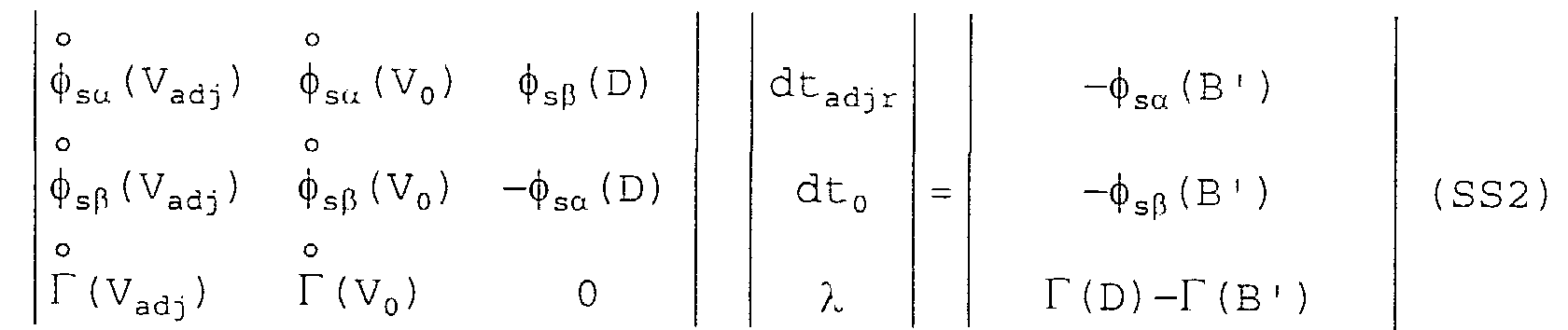
- Procédé de régulation selon la revendication 4 caractérisé en ce quelors de l'étape c), le calculateur résout le système suivant :
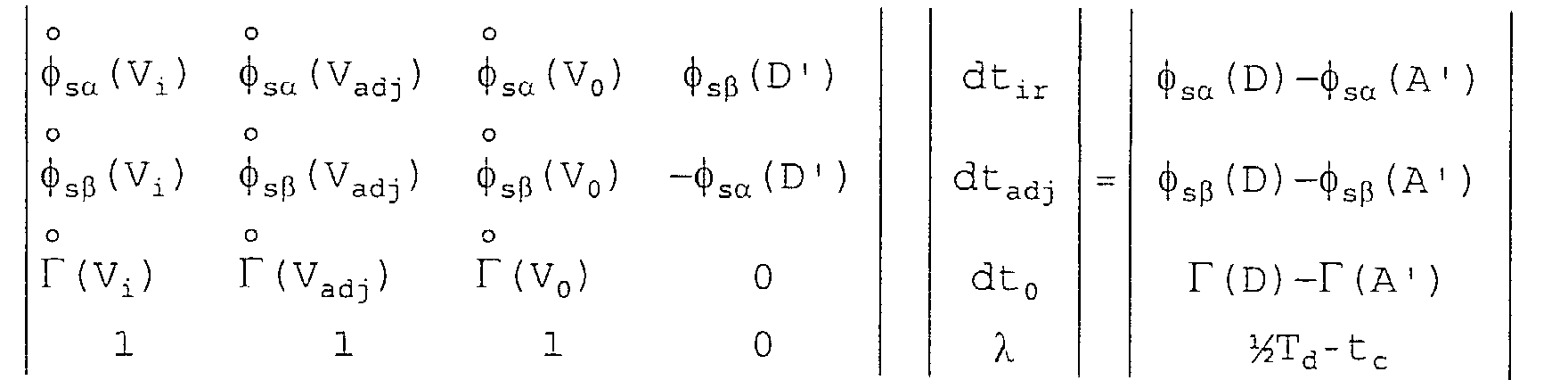 où λ est un paramètre définissant la position du point D sur une tangente au cercle ηcal en D', etlors de l'étape f), le calculateur résout le système suivant par la méthode des moindres carrés: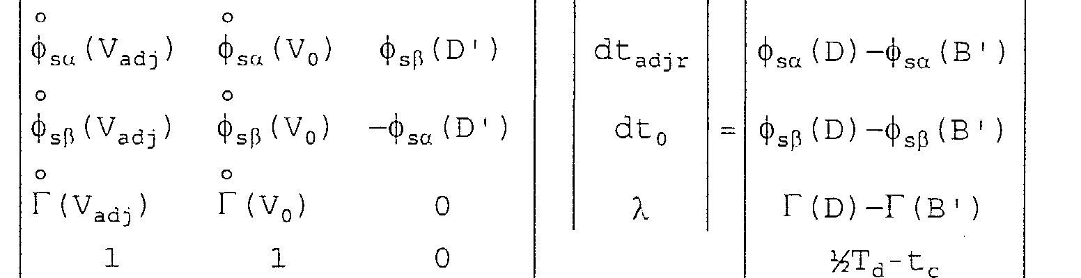
- Procédé selon la revendication 4 ou 5 caractérisé en ce que lors de l'étape i)
le calculateur calcule pour le point courant C'(sαc, sβc, Γc) le temps restant dt0r d'application de l'état V0 en résolvant par la méthode des moindres carrés le système suivant :
- Procédé selon la revendication 4 caractérisé en ce que lors de l'étape d) le calculateur prévoit la commutation de l'état Vi vers l'autre état adjacent de Vi afin de recadrer la trajectoire du point B' vers le cercle ηcal.
- Procédé selon la revendication 4 ou 5 caractérisé en ce que lorsqu'il n'existe pas de triplette unique (V0, Vi, Vadj), alors le calculateur recherche une succession de deux états (Vi, Vadj) différents d'un état nul permettant de rapprocher au mieux le point A (sα, β, Γ) du cercle ηref dans l'intervalle de temps ½Td.
- Procédé de régulation selon la revendication 1, le calculateur effectuant les calculs dans un référentiel de calcul tridimensionnel orthogonal comprenant le plan statorique (sα, sβ) du flux stator S et un axe, perpendiculaire audit plan statorique (sα, sβ), représentant le couple Γ, les consignes Γref, |S|ref, étant représentées par un cercle ηref contenu dans un plan parallèle au plan statorique (sα ,sβ), centré sur ledit axe perpendiculaire, ayant un rayon de |S|ref et interceptant ledit axe perpendiculaire en Γref, les valeurs Γ, S fournies par la machine tournante, étant représentées par un point A (sα, sβ, Γ) sur un cercle η contenu dans un plan parallèle au plan statorique (sα, sβ), centré sur ledit axe perpendiculaire, ayant un rayon de |S| et interceptant ledit axe perpendiculaire en Γ,
le procédé étant caractérisé en ce que la stratégie de contrôle est une stratégie synchrone avec la fréquence de rotation de la machine tournante dans laquelle la succession de n états du vecteur tension est calculée pour que le point A (sα, sβ , Γ) rallie un point D d'un cercle ηcal, centré sur ledit axe perpendiculaire, ayant un rayon de |S|cal et interceptant ledit axe perpendiculaire en Γcal, par application successive des n états, avec une position finale prédéterminée du vecteur flux statorique dans le plan stator (sα, sβ), ledit calculateur calculant l'équation du cercle ηcal pour que sur la durée d'application de la succession, le couple Γ moyen et le flux statorique |S| moyen générés soient sensiblement égaux respectivement aux consignes Γref, |S|ref. - Procédé de régulation selon la revendication 9 caractérisé en ce que le nombre de position prédéterminées autorisées par tour de flux statorique est fini et fonction d'une plage de vitesse de rotation de la machine tournante.
- Procédé de régulation selon la revendication 9 et 10 caractérisé en ce que, n étant égal à trois, la stratégie de contrôle est telle que le calculateur connaít une triplette unique d'états (V0, Vi, Vadj) i∈{2...mn-1} du vecteur tension constituant une succession de trois états, comprenant un état de départ Vi, un des deux états Vadj adjacent à Vi et un état nul (V0), dont les temps d'application respectifs dti, dtadj, dt0 sont positifs, ladite triplette permettant de rejoindre le cercl ηcal en un point D connu.
- Procédé de régulation selon la revendication 11 caractérisé en ce que,dans une étape d'initialisation de la machine tournante, on met en mémoire dans le calculateur des triplettes (V0, Vi, Vadj) i∈{2...mn-1}, pour passer d'une position prédéterminée à une autre position prédéterminée du vecteur flux stator, selon divers plages de vitesse de rotation de la machine tournante, eten fonctionnement,a) le calculateur connaít la triplette (V0, Vi, Vadj) à appliquer en fonction de la vitesse de rotation de la machine tournante et de la position prédéterminé dans laquelle est le vecteur flux stator,b) il envoi des signaux de commande des SPmLL pour commuter dans l'état Vi,c) à chaque échantillonnage, le calculateur calcule, pour le point courant A'(sαc, sβc, Γc), le temps restant dtir d'application de l'état Vi et les temps dtadj et dt0 mis à jour des états futurs Vadj et V0,d) lorsque dtir≤Te, le calculateur prévoit l'instant de commutation de l'état Vi vers l'état Vadj,e) de façon asynchrone avec les instants d'échantillonnage et de calcul, lorsque l'instant de commutation arrive, le calculateur envoi des signaux de commande des SPmLL pour commuter dans l'état Vadj,f) à chaque échantillonnage, le calculateur calcule, pour le point courant B'(sαc, sβc, Γc), le temps restant dtadjr d'application de l'état Vadj et le temps dt0 mis à jour de l'état futur V0,g) lorsque dtadjr≤Te, le calculateur prévoit l'instant de commutation de l'état Vadj vers l'état V0,h) de façon asynchrone avec les instants d'échantillonnage et de calcul, lorsque l'instant de commutation arrive, le calculateur envoi des signaux de commande des SPmLL pour commuter dans l'état V0,i) à chaque échantillonnage, le calculateur calcule pour le point courant C'(sαc, sβc, Γc) le temps restant dt0r d'application de l'état V0,j) lorsque dt0r≤Te, prévoit l'instant de commutation de l'état V0 vers l'état V'i, en outre le calculateur connaít la nouvelle triplette unique (V'0, V'i, V'adj) permettant de passer de la position prédéterminée qui va être atteinte à la position prédéterminée suivante du vecteur flux stator, etk) de façon asynchrone avec les instants d'échantillonnage et de calcul, lorsque l'instant de commutation arrive, le calculateur envoi des signaux de commande des SPmLL pour commuter dans l'état V'i,le calculateur traitant la nouvelle triplette (V'0, V'i, V'adj) selon les étapes c) à k).
- Procédé de régulation selon la revendication 12 caractérisé en ce que lors de l'étape c), le calculateur résout le système suivant:
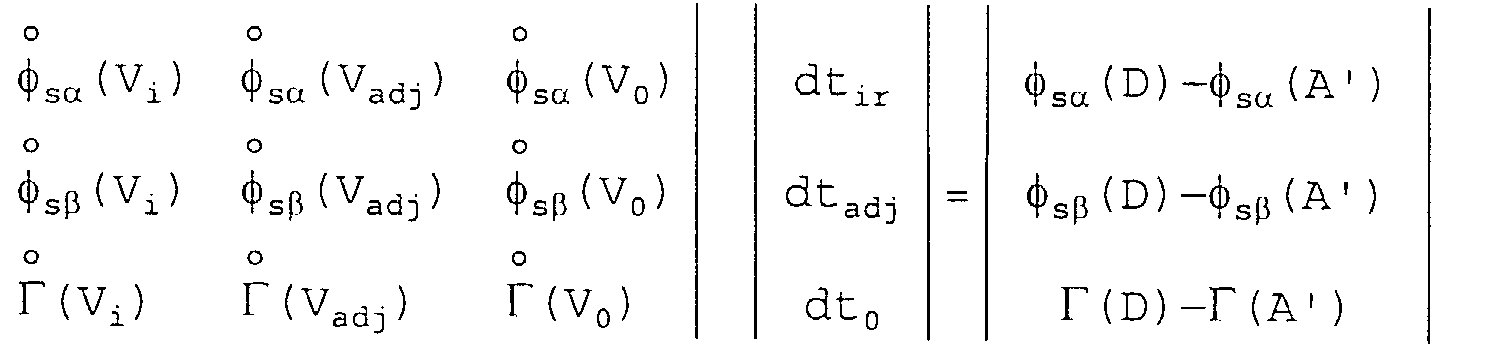 lors de l'étape f), le calculateur résout le système suivant :
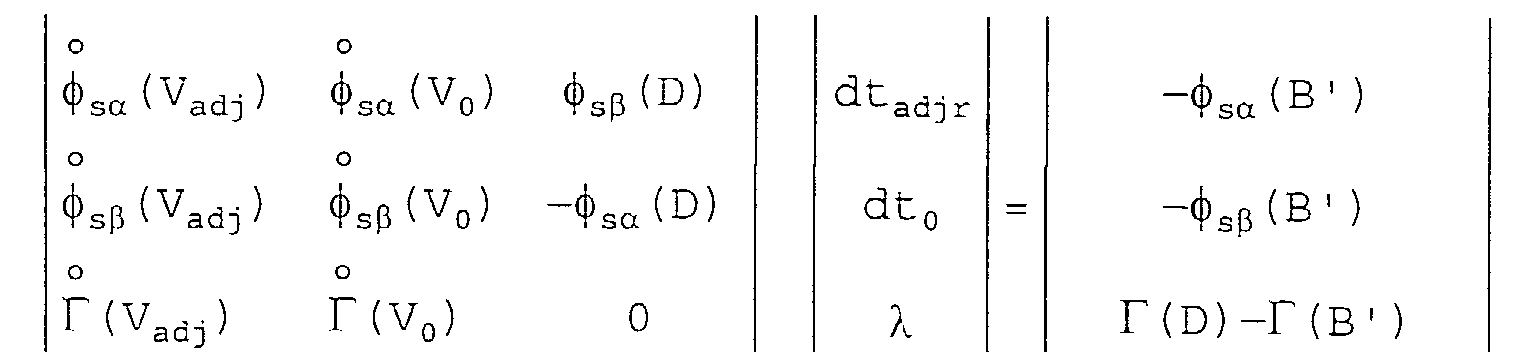 où λ est un paramètre définissant la position finale prévisible du point courant B' sur une droite contenue dans le plan statorique, passant par l'axe de couple Γ et parallèle à la position prédéterminée du vecteur de flux statorique qui doit être atteinte.
 - Procédé selon la revendication 12 ou 13 caractérisé en ce que lors de l'étape i)le calculateur calcule pour le point courant C'(sαc, sβc, Γc) le temps restant dt0r d'application de l'état V0 en résolvant le système suivant :
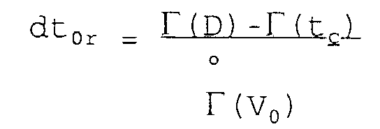 où Γmoyen est le couple électromagnétique moyen calculé sur l'intervalle de temps dti + dtadj.
 - Procédé selon l'une quelconque des revendications 11 à 14 caractérisé en ce que le temps dt0 d'application de l'état nul est une fonction décroissante de la vitesse de rotation de la machine tournante, et égal à zéro au-delà d'une valeur prédéterminée de la vitesse de rotation de la machine tournante.
- Procédé selon la revendication 15 caractérisé en ce que lorsque le temps dt0 d'application de l'état nul est égal à zéro, le couple est régulé par un correcteur de flux en fonction de ΔΓ = Γref - Γc suivant les règles suivantes :Pour ΔΓ > 0 , le correcteur diminue la norme du flux stator;Pour ΔΓ < 0, le correcteur augmente la norme du flux stator.
- Système d'asservissement d'une machine tournante à n phases alimentée en courant alternatif par l'intermédiaire d'un onduleur de tension comprenant n SPmLL définissant mn états du vecteur tension de phase stator, le système d'asservissement, pouvant suivre différentes stratégies de contrôle, asservissant la machine en couple électromagnétique Γ et en flux statorique |S| à des consignes Γref, |S|ref, chaque stratégie ayant des conditions d'application, ledit système d'asservissement comprenant un ensemble de capteurs dont les valeurs captées sont transmises à un observateur-échantillonneur, les sorties de l'observateur, échantillonnées selon une période d'échantillonnage donnée Te, étant injectées dans un calculateur, ledit calculateur restituant en sortie des signaux de commande des SPmLL de l'onduleur de tension, caractérisé en ce qu'il met en oeuvre le procédé selon l'une quelconque des revendication 1 à 16.
- Machine tournante à n phases alimentée en courant alternatif par l'intermédiaire d'un onduleur de tension comprenant n SPmLL définissant mn états du vecteur tension de phase stator, ladite machine étant asservie en couple électromagnétique Γ et en flux statorique |S| à des consignes Γref, |S|ref par un système d'asservissement pouvant suivre différentes stratégies de contrôle, chaque stratégie ayant des conditions d'application, ledit système d'asservissement comprenant un ensemble de capteurs dont les valeurs captées sont transmises à un observateur-échantillonneur, les sorties de l'observateur, échantillonnées selon une période d'échantillonnage donnée Te, étant injectées dans un calculateur, ledit calculateur restituant en sortie des signaux de commande des SPmLL de l'onduleur de tension, caractérisée en ce que le système d'asservissement est selon la revendication 17.
Applications Claiming Priority (2)
| Application Number | Priority Date | Filing Date | Title |
|---|---|---|---|
| FR9701346 | 1997-02-06 | ||
| FR9701346A FR2759216B1 (fr) | 1997-02-06 | 1997-02-06 | Procede de regulation d'une machine tournante, systeme d'asservissement pour mettre en oeuvre ledit procede, et machine tournante pourvue d'un tel systeme |
Publications (1)
| Publication Number | Publication Date |
|---|---|
| EP0858155A1 true EP0858155A1 (fr) | 1998-08-12 |
Family
ID=9503393
Family Applications (1)
| Application Number | Title | Priority Date | Filing Date |
|---|---|---|---|
| EP98400187A Withdrawn EP0858155A1 (fr) | 1997-02-06 | 1998-01-29 | Procédé de régulation d'une machine tournante, système d'asservissement pour mettre en oeuvre ledit procédé, et machine tournante pourvue d'un tel système |
Country Status (10)
| Country | Link |
|---|---|
| US (1) | US6087801A (fr) |
| EP (1) | EP0858155A1 (fr) |
| JP (1) | JPH10240349A (fr) |
| KR (1) | KR19980071133A (fr) |
| CN (1) | CN1193843A (fr) |
| AU (1) | AU725374B2 (fr) |
| BR (1) | BR9800572A (fr) |
| CA (1) | CA2226390A1 (fr) |
| FR (1) | FR2759216B1 (fr) |
| TW (1) | TW373365B (fr) |
Cited By (2)
| Publication number | Priority date | Publication date | Assignee | Title |
|---|---|---|---|---|
| FR2785470A1 (fr) * | 1998-11-04 | 2000-05-05 | Cegelec | Procede de commande pour machine electrique tournante, systeme d'asservissement pour la mise en oeuvre de ce procede et machine tournante equipee d'un tel systeme |
| RU2417513C1 (ru) * | 2010-05-18 | 2011-04-27 | Государственное образовательное учреждение высшего профессионального образования "Санкт-Петербургский государственный горный институт имени Г.В. Плеханова (технический университет)" | Устройство автоматического управления электроприводом переменного тока при питании от источника ограниченной мощности |
Families Citing this family (7)
| Publication number | Priority date | Publication date | Assignee | Title |
|---|---|---|---|---|
| US6556941B2 (en) * | 2000-10-27 | 2003-04-29 | Ade Corporation | Separation of periodic and non-periodic signal components |
| WO2003073185A2 (fr) * | 2002-02-28 | 2003-09-04 | Zetacon Corporation | Systeme et procede de commande predictive |
| US7274865B2 (en) * | 2003-09-04 | 2007-09-25 | Patricio Lagos Lehuede | General purpose 100% solid state drive for direct current rotary machines |
| US8086645B2 (en) * | 2003-12-16 | 2011-12-27 | Oracle International Corporation | Compilation and processing a parallel single cursor model |
| FR2985112B1 (fr) * | 2011-12-21 | 2014-01-03 | Soc Tech Michelin | Onduleur de pilotage avec detecteur d'erreur de couple |
| CN106253782A (zh) * | 2016-07-27 | 2016-12-21 | 西安理工大学 | 基于最小二乘法的扩展卡尔曼滤波异步电机转速估计方法 |
| CN114446685B (zh) * | 2020-10-30 | 2024-03-01 | 北京铁路信号有限公司 | 一种开关控制装置与一种铁路信号记录器 |
Family Cites Families (12)
| Publication number | Priority date | Publication date | Assignee | Title |
|---|---|---|---|---|
| DE3212439C2 (de) * | 1982-04-02 | 1992-02-20 | Robert Prof.Dr.-Ing. 6100 Darmstadt Jötten | Verfahren zum Betrieb einer durch schnelle elektrische Stellglieder gespeisten Asynchronmaschine |
| DE3438504A1 (de) * | 1984-10-20 | 1986-04-24 | Brown, Boveri & Cie Ag, 6800 Mannheim | Verfahren und einrichtung zur regelung einer drehfeldmaschine |
| US4959573A (en) * | 1986-08-27 | 1990-09-25 | S.P.C. Holding, Co., Ltd. | Electromagnetic induction machines having regulated polar magnetic symmetry |
| FR2614481B1 (fr) * | 1987-02-13 | 1990-08-31 | Pk I | Procede de commande d'un moteur asynchrone et entrainement electrique mettant ce procede en application |
| JPH0742056B2 (ja) * | 1989-06-15 | 1995-05-10 | 三菱電機株式会社 | 流体圧エレベータ制御装置 |
| US5334923A (en) * | 1990-10-01 | 1994-08-02 | Wisconsin Alumni Research Foundation | Motor torque control method and apparatus |
| JPH05130791A (ja) * | 1991-11-05 | 1993-05-25 | Sanken Electric Co Ltd | モ−タ制御方法 |
| US5440219A (en) * | 1993-05-21 | 1995-08-08 | Wilkerson; Alan W. | Induction motor speed control having improved sensing of motor operative conditions |
| US5585709A (en) * | 1993-12-22 | 1996-12-17 | Wisconsin Alumni Research Foundation | Method and apparatus for transducerless position and velocity estimation in drives for AC machines |
| ATE181472T1 (de) * | 1994-03-23 | 1999-07-15 | Abb Daimler Benz Transp | Verfahren zur drehmomentregelung einer asynchronmaschine |
| JPH08289600A (ja) * | 1995-04-18 | 1996-11-01 | Okuma Mach Works Ltd | 誘導電動機の制御装置 |
| US5648705A (en) * | 1995-09-05 | 1997-07-15 | Ford Motor Company | Motor vehicle alternator and methods of operation |
-
1997
- 1997-02-06 FR FR9701346A patent/FR2759216B1/fr not_active Expired - Fee Related
-
1998
- 1998-01-29 EP EP98400187A patent/EP0858155A1/fr not_active Withdrawn
- 1998-02-03 TW TW087101323A patent/TW373365B/zh active
- 1998-02-05 AU AU52938/98A patent/AU725374B2/en not_active Ceased
- 1998-02-05 US US09/019,437 patent/US6087801A/en not_active Expired - Fee Related
- 1998-02-05 CA CA002226390A patent/CA2226390A1/fr not_active Abandoned
- 1998-02-06 CN CN98106347A patent/CN1193843A/zh active Pending
- 1998-02-06 KR KR1019980003416A patent/KR19980071133A/ko not_active Ceased
- 1998-02-06 JP JP10025566A patent/JPH10240349A/ja active Pending
- 1998-05-06 BR BR9800572-3A patent/BR9800572A/pt not_active IP Right Cessation
Non-Patent Citations (3)
| Title |
|---|
| HOFFMANN F ET AL: "FAST TORQUE CONTROL OF AN IGBT-INVERTER-FED THREE-PHASE A.C. DRIVE IN THE WHOLE SPEED RANGE EXPERIMENTAL RESULTS", 19 September 1995, EPE '95: 6TH. EUROPEAN CONFERENCE ON POWER ELECTRONICS AND APPLICATIONS, SEVILLA, SEPT. 19 - 21, 1995, VOL. 3, PAGE(S) 3.399 - 3.404, EUROPEAN POWER ELECTRONICS AND DRIVES ASSOCIATION, XP000538343 * |
| HOLTZ J ET AL: "OPTIMAL PULSEWIDTH MODULATION FOR AC SERVOS AND LOW-COST INDUSTRIAL DRIVES", July 1994, IEEE TRANSACTIONS ON INDUSTRY APPLICATIONS, VOL. 30, NR. 4, PAGE(S) 1039 - 1047, XP000469586 * |
| THOGERSEN P. ET AL.: "Stator flux oriented asynchronous vector modulation for AC-drives", PESC'90 RECORD. 21ST ANNUAL IEEE POWER ELECTRONICS SPECIALISTS CONFERENCE, vol. 2, 1990, SAN ANNEW YORK, USA, pages 641 - 648, XP002043849 * |
Cited By (4)
| Publication number | Priority date | Publication date | Assignee | Title |
|---|---|---|---|---|
| FR2785470A1 (fr) * | 1998-11-04 | 2000-05-05 | Cegelec | Procede de commande pour machine electrique tournante, systeme d'asservissement pour la mise en oeuvre de ce procede et machine tournante equipee d'un tel systeme |
| EP0999639A1 (fr) * | 1998-11-04 | 2000-05-10 | Alstom Entreprise SA | Procédé de commande pour machine électrique tournante, système d'asservissement pour la mise en oeuvre de ce procédé et machine tournante pourvue d'un tel système |
| US6198248B1 (en) | 1998-11-04 | 2001-03-06 | Alstom Enterprise Sa | Method of controlling a rotary electrical machine, a servo-control system for implementing the method, and a rotary machine fitted with such a system |
| RU2417513C1 (ru) * | 2010-05-18 | 2011-04-27 | Государственное образовательное учреждение высшего профессионального образования "Санкт-Петербургский государственный горный институт имени Г.В. Плеханова (технический университет)" | Устройство автоматического управления электроприводом переменного тока при питании от источника ограниченной мощности |
Also Published As
| Publication number | Publication date |
|---|---|
| BR9800572A (pt) | 1999-09-21 |
| JPH10240349A (ja) | 1998-09-11 |
| FR2759216B1 (fr) | 1999-03-05 |
| AU5293898A (en) | 1998-08-13 |
| FR2759216A1 (fr) | 1998-08-07 |
| AU725374B2 (en) | 2000-10-12 |
| TW373365B (en) | 1999-11-01 |
| CN1193843A (zh) | 1998-09-23 |
| CA2226390A1 (fr) | 1998-08-06 |
| KR19980071133A (ko) | 1998-10-26 |
| US6087801A (en) | 2000-07-11 |
Similar Documents
| Publication | Publication Date | Title |
|---|---|---|
| EP0579948B1 (fr) | Dispositif de commande d'un moteur asynchrone | |
| EP2246973B1 (fr) | Procédé de détermination de la position du vecteur de flux d'un moteur | |
| FR2911698A1 (fr) | Dispositif de commande d'actionneur electromecanique. | |
| EP0858155A1 (fr) | Procédé de régulation d'une machine tournante, système d'asservissement pour mettre en oeuvre ledit procédé, et machine tournante pourvue d'un tel système | |
| FR2681483A1 (fr) | Circuit de commande de moteur a induction. | |
| EP0812059B1 (fr) | Procédé de contrôle commande d'une machine tournante, dispositif d'asservissement pour mettre en oeuvre ledit procédé et application du dispositif à une machine tournante | |
| WO2001001559A1 (fr) | Procede de commande en couple, d'un moteur a induction, a l'aide d'un gradateur de tension | |
| EP4216424A1 (fr) | Procédé et système de commande d'une machine électrique pilotée par un onduleur pourvu de plusieurs bras de commutation avec deux methodes d'asservissement | |
| FR2682922A1 (fr) | Procede et dispositif de freinage de vehicules par asservissement du couple de freinage applique sur une roue. | |
| EP1484835A2 (fr) | Procédé et système de régulation du couple électromagnétique instantané, et support d'enregistrement pour la mise en oeuvre du procédé | |
| EP4229748A1 (fr) | Procede et systeme de controle d'une machine electrique determinant des consignes de courant optimales | |
| EP2605400B1 (fr) | Procédé de commande d'un onduleur pour l'alimentation électrique d'un moteur, et module de commande associé | |
| EP0473731B1 (fr) | Procede et dispositif de comparaison de deux signaux analogiques variables | |
| EP0702451A1 (fr) | Dispositif de commande d'un moteur synchrone | |
| EP0999639A1 (fr) | Procédé de commande pour machine électrique tournante, système d'asservissement pour la mise en oeuvre de ce procédé et machine tournante pourvue d'un tel système | |
| WO2023062167A1 (fr) | Procédé d'estimation de la position et de la vitesse du rotor d'une machine électrique synchrone à aimant permanent | |
| EP1420319A1 (fr) | Procédé et dispositif pour la détection de couplages oscillatoires de pilotage dans un aéronef | |
| EP0105033B1 (fr) | Dispositif pour la commande d'un moteur à courant continu | |
| EP1586858B1 (fr) | Procédé de commande en push-pull d'un gyrometre à laser | |
| EP3824540B1 (fr) | Procédé de détermination de la position et de la vitesse du rotor d'une machine électrique synchrone à rotor bobiné | |
| EP4454119B1 (fr) | Procede et systeme de commande d'une machine electrique pilotee par un onduleur pourvu de plusieurs bras de commutation | |
| EP0119374B1 (fr) | Procédé pour le contrôle de la marche d'une machine électrique et dispositif appliquant ce procédé | |
| EP1598555A1 (fr) | Système de groupe électro-pompe pourvu de moyens de limitation de la pression du fluide hydraulique fourni par la pompe | |
| EP3529889B1 (fr) | Procedes et dispositifs relatifs a l'estimation d'une position angulaire d'un rotor | |
| EP0959556A1 (fr) | Système de régulation de moteur asynchrone à énergie minimale par commande à flux orienté |
Legal Events
| Date | Code | Title | Description |
|---|---|---|---|
| PUAI | Public reference made under article 153(3) epc to a published international application that has entered the european phase |
Free format text: ORIGINAL CODE: 0009012 |
|
| AX | Request for extension of the european patent |
Free format text: AL;LT;LV;MK;RO;SI |
|
| RAP3 | Party data changed (applicant data changed or rights of an application transferred) |
Owner name: ALCATEL |
|
| RAP3 | Party data changed (applicant data changed or rights of an application transferred) |
Owner name: ALCATEL |
|
| 17P | Request for examination filed |
Effective date: 19990212 |
|
| AKX | Designation fees paid |
Free format text: BE DE ES GB IT NL SE |
|
| RBV | Designated contracting states (corrected) |
Designated state(s): BE DE ES GB IT NL SE |
|
| RAP1 | Party data changed (applicant data changed or rights of an application transferred) |
Owner name: ALCATEL LUCENT |
|
| STAA | Information on the status of an ep patent application or granted ep patent |
Free format text: STATUS: THE APPLICATION IS DEEMED TO BE WITHDRAWN |
|
| 18D | Application deemed to be withdrawn |
Effective date: 20070801 |