EP0858785A1 - Matériel pour la fixation d'un tendon de muscle sur un os - Google Patents
Matériel pour la fixation d'un tendon de muscle sur un os Download PDFInfo
- Publication number
- EP0858785A1 EP0858785A1 EP98400214A EP98400214A EP0858785A1 EP 0858785 A1 EP0858785 A1 EP 0858785A1 EP 98400214 A EP98400214 A EP 98400214A EP 98400214 A EP98400214 A EP 98400214A EP 0858785 A1 EP0858785 A1 EP 0858785A1
- Authority
- EP
- European Patent Office
- Prior art keywords
- rod
- bone
- material according
- head
- intended
- Prior art date
- Legal status (The legal status is an assumption and is not a legal conclusion. Google has not performed a legal analysis and makes no representation as to the accuracy of the status listed.)
- Granted
Links
- 210000000988 bone and bone Anatomy 0.000 title claims abstract description 24
- 210000002435 tendon Anatomy 0.000 title claims abstract description 7
- 210000003205 muscle Anatomy 0.000 claims abstract description 16
- 210000005069 ears Anatomy 0.000 claims description 5
- 238000004873 anchoring Methods 0.000 claims description 4
- 230000003387 muscular Effects 0.000 claims description 2
- JVTAAEKCZFNVCJ-REOHCLBHSA-N L-lactic acid Chemical compound C[C@H](O)C(O)=O JVTAAEKCZFNVCJ-REOHCLBHSA-N 0.000 description 1
- 238000005553 drilling Methods 0.000 description 1
- 210000002758 humerus Anatomy 0.000 description 1
- 229920001432 poly(L-lactide) Polymers 0.000 description 1
- 210000000513 rotator cuff Anatomy 0.000 description 1
- 238000004513 sizing Methods 0.000 description 1
Images


Classifications
-
- A—HUMAN NECESSITIES
- A61—MEDICAL OR VETERINARY SCIENCE; HYGIENE
- A61F—FILTERS IMPLANTABLE INTO BLOOD VESSELS; PROSTHESES; DEVICES PROVIDING PATENCY TO, OR PREVENTING COLLAPSING OF, TUBULAR STRUCTURES OF THE BODY, e.g. STENTS; ORTHOPAEDIC, NURSING OR CONTRACEPTIVE DEVICES; FOMENTATION; TREATMENT OR PROTECTION OF EYES OR EARS; BANDAGES, DRESSINGS OR ABSORBENT PADS; FIRST-AID KITS
- A61F2/00—Filters implantable into blood vessels; Prostheses, i.e. artificial substitutes or replacements for parts of the body; Appliances for connecting them with the body; Devices providing patency to, or preventing collapsing of, tubular structures of the body, e.g. stents
- A61F2/02—Prostheses implantable into the body
- A61F2/08—Muscles; Tendons; Ligaments
- A61F2/0811—Fixation devices for tendons or ligaments
-
- A—HUMAN NECESSITIES
- A61—MEDICAL OR VETERINARY SCIENCE; HYGIENE
- A61F—FILTERS IMPLANTABLE INTO BLOOD VESSELS; PROSTHESES; DEVICES PROVIDING PATENCY TO, OR PREVENTING COLLAPSING OF, TUBULAR STRUCTURES OF THE BODY, e.g. STENTS; ORTHOPAEDIC, NURSING OR CONTRACEPTIVE DEVICES; FOMENTATION; TREATMENT OR PROTECTION OF EYES OR EARS; BANDAGES, DRESSINGS OR ABSORBENT PADS; FIRST-AID KITS
- A61F2/00—Filters implantable into blood vessels; Prostheses, i.e. artificial substitutes or replacements for parts of the body; Appliances for connecting them with the body; Devices providing patency to, or preventing collapsing of, tubular structures of the body, e.g. stents
- A61F2/02—Prostheses implantable into the body
- A61F2/08—Muscles; Tendons; Ligaments
- A61F2/0811—Fixation devices for tendons or ligaments
- A61F2002/0847—Mode of fixation of anchor to tendon or ligament
- A61F2002/087—Anchor integrated into tendons, e.g. bone blocks, integrated rings
-
- A—HUMAN NECESSITIES
- A61—MEDICAL OR VETERINARY SCIENCE; HYGIENE
- A61F—FILTERS IMPLANTABLE INTO BLOOD VESSELS; PROSTHESES; DEVICES PROVIDING PATENCY TO, OR PREVENTING COLLAPSING OF, TUBULAR STRUCTURES OF THE BODY, e.g. STENTS; ORTHOPAEDIC, NURSING OR CONTRACEPTIVE DEVICES; FOMENTATION; TREATMENT OR PROTECTION OF EYES OR EARS; BANDAGES, DRESSINGS OR ABSORBENT PADS; FIRST-AID KITS
- A61F2/00—Filters implantable into blood vessels; Prostheses, i.e. artificial substitutes or replacements for parts of the body; Appliances for connecting them with the body; Devices providing patency to, or preventing collapsing of, tubular structures of the body, e.g. stents
- A61F2/02—Prostheses implantable into the body
- A61F2/08—Muscles; Tendons; Ligaments
- A61F2/0811—Fixation devices for tendons or ligaments
- A61F2002/0876—Position of anchor in respect to the bone
- A61F2002/0882—Anchor in or on top of a bone tunnel, i.e. a hole running through the entire bone
-
- A—HUMAN NECESSITIES
- A61—MEDICAL OR VETERINARY SCIENCE; HYGIENE
- A61F—FILTERS IMPLANTABLE INTO BLOOD VESSELS; PROSTHESES; DEVICES PROVIDING PATENCY TO, OR PREVENTING COLLAPSING OF, TUBULAR STRUCTURES OF THE BODY, e.g. STENTS; ORTHOPAEDIC, NURSING OR CONTRACEPTIVE DEVICES; FOMENTATION; TREATMENT OR PROTECTION OF EYES OR EARS; BANDAGES, DRESSINGS OR ABSORBENT PADS; FIRST-AID KITS
- A61F2250/00—Special features of prostheses classified in groups A61F2/00 - A61F2/26 or A61F2/82 or A61F9/00 or A61F11/00 or subgroups thereof
- A61F2250/0004—Special features of prostheses classified in groups A61F2/00 - A61F2/26 or A61F2/82 or A61F9/00 or A61F11/00 or subgroups thereof adjustable
- A61F2250/0007—Special features of prostheses classified in groups A61F2/00 - A61F2/26 or A61F2/82 or A61F9/00 or A61F11/00 or subgroups thereof adjustable for adjusting length
-
- Y—GENERAL TAGGING OF NEW TECHNOLOGICAL DEVELOPMENTS; GENERAL TAGGING OF CROSS-SECTIONAL TECHNOLOGIES SPANNING OVER SEVERAL SECTIONS OF THE IPC; TECHNICAL SUBJECTS COVERED BY FORMER USPC CROSS-REFERENCE ART COLLECTIONS [XRACs] AND DIGESTS
- Y10—TECHNICAL SUBJECTS COVERED BY FORMER USPC
- Y10S—TECHNICAL SUBJECTS COVERED BY FORMER USPC CROSS-REFERENCE ART COLLECTIONS [XRACs] AND DIGESTS
- Y10S606/00—Surgery
- Y10S606/907—Composed of particular material or coated
- Y10S606/908—Bioabsorbable material
Definitions
- the present invention relates to equipment for fixing a muscle tendon on a bone.
- An object of the invention is to overcome this disadvantage.
- a muscle tendon on a bone characterized in what it includes a rod intended to cross the tendon and a channel previously drilled in the bone and opening at these two ends, a fixing head which ends said rod and which is intended to come to bear on the muscle to hold it against the bone and a locking element capable of cooperating with the rod its end which is opposite to the fixing head and which is intended to emerge from the transosseous tunnel, for block said rod and its head relative to the bone and muscular.
- the fastening material illustrated in Figure 1 comprises a rod 1, a fixing head 2, as well as a locking element 3.
- Rod 1 which was more particularly illustrated in Figure 2, has a cylindrical body which ends at one end with a point 4 and at a other end by a ball 5 of semi-spherical shape (sphere cut by a flat perpendicular to the axis of the rod 1).
- the body of said rod 1 present on a part of its length, on the side of the ball 5 (part referenced by 7 in the figures), a plurality of notched zones 7a evenly distributed and separated by smooth areas 7b.
- the notched areas 7a are defined by successions of tapered, flaring teeth in the direction of the ball 5.
- the rod 1 ends in a smooth part 8.
- the fixing head 2 (FIGS. 3 and 4) has an elongated shape defined by two ears 9, of shape flat, arranged on either side of a central area 10.
- the central zone 10 is crossed by an orifice which has a portion 10a of semi-spherical shape intended to cooperate with the ball 5 to allow the articulation of the fixing head 2 relative to the rod 1.
- This central zone also includes a portion cylindrical 10b which extends from the bottom of the portion 10a.
- This fixing head 2 is intended to be threaded on the rod 1, by the tip 4 thereof, and at be reassembled so that the portion 10a comes to cap the ball 5.
- the internal diameter of the portion 10b is chosen with sufficient clearance compared to the diameter of the rod 1 and to the dimensions of the teeth of the notched zones 7a for allow the head 2 to rise along the rod 1, as well as adjusting the orientation of said head 2 by compared to stem 1.
- Each of the flat ears 9 carries, on its face which is on the side of the body of the rod 1 when the head 2 is in place on said rod 1, a point 11 for anchoring conical shape.
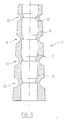
- the locking element 3 ( Figure 5) is constituted by a tube of interior shape mainly cylindrical and of generally external shape slightly tapered. This locking element 3 has in its inside a plurality of notches 12 intended to cooperate with the notches of the rod 1.
- These notches 12 are elastic skirts of shape frustoconical, which are intended to fade elastically when the locking element is reassembled on the rod 1 and to oppose efforts which would tend to make descend said locking element 3 along said rod 1.
- Notch step 12 is double notch notch zones 7a.
- Semi-toroidal annular recesses 13 are provided on the outer face of this element of lock 3, to the right of the skirts 12 to give this one a maximum elasticity.
- the diameter of the smooth parts of the rod 1 can be 1.5 mm.
- the smooth part 8 can be of a length of 95 mm, the notched part 7 being 70 mm.
- the notched zones 7a of part 7 can be 10 mm high, smooth areas 7b with which they alternate being of a 5 mm high.
- the diameter of the large base of the teeth in the area 7a is 2 mm
- the ball 5 is for example of a diameter of 2.25 mm and 1.5 mm high.
- the internal diameter of the orifice 10b of the head 2 is 1.6 mm.
- the points 11 are 1 mm high, the ears 9 being 0.8 mm thick.
- the internal diameter of the element 3 is 2 mm, its height being 11 mm, its external diameter varying from 4 at 2.9 mm.
- the frustoconical notches 12 are for example of a height of 0.5 mm, the distance between the ends of two successive notches 12 being for example 2.5 mm.
- the materials of rod 1, head 2 and the locking element 3 are absorbable (PLLA or PGA for example).
- the inner diameter is for example for material dimensions mentioned above, 3.2 mm.
- the fixing head 2 being previously put in place on the rod 1, this is introduced into the supraspinatus then in the tunnel prepared by the surgeon in the bone.
- the surgeon directs the fixation head 2 in function of the grip he wishes to achieve on the muscle and positions said head so that it maintains the muscle on the bone.
- the clamping pressure of element 3 against the bone is for example controlled by a tool provided for this purpose.
Landscapes
- Health & Medical Sciences (AREA)
- Orthopedic Medicine & Surgery (AREA)
- Rehabilitation Therapy (AREA)
- Rheumatology (AREA)
- Cardiology (AREA)
- Oral & Maxillofacial Surgery (AREA)
- Transplantation (AREA)
- Engineering & Computer Science (AREA)
- Biomedical Technology (AREA)
- Heart & Thoracic Surgery (AREA)
- Vascular Medicine (AREA)
- Life Sciences & Earth Sciences (AREA)
- Animal Behavior & Ethology (AREA)
- General Health & Medical Sciences (AREA)
- Public Health (AREA)
- Veterinary Medicine (AREA)
- Prostheses (AREA)
- Surgical Instruments (AREA)
Abstract
Description
- la tige se termine par une rotule sur laquelle la tête de fixation est articulée ;
- pour sa coopération avec l'élément de verrouillage, la tige présente une pluralité de crans répartis sur au moins une partie de sa longueur ;
- la tige présente une pluralité de zones crantées alternant avec des zones lisses ;
- l'élément de verrouillage est un tube qui est extérieurement de forme générale tronconique et qui est destiné à se fixer sur l'os par serrage de sa paroi tronconique dans le canal foré dans l'os ;
- l'élément de verrouillage présente une pluralité de crans internes destinés à coopérer avec les crans portés par la tige pour permettre le coulissement de l'élément de verrouillage le long de la tige dans un sens et s'opposer à un coulissement en sens contraire ;
- l'élément de verrouillage présente des évidements annulaires au droit des crans internes ;
- la tête présente au moins une pointe pour son ancrage dans le muscle ;
- la tête présente deux oreilles de part et d'autre d'une zone centrale, chaque oreille portant une pointe d'ancrage.
- la figure 1 est une vue en plan d'un matériel de fixation conforme à un mode de réalisation possible de l'invention ;
- la figure 2 est une représentation en deux parties de la tige du matériel de la figure 1 ;
- la figure 3 est une vue de dessus de la tête de fixation du matériel de la figure 1 ;
- la figure 4 est une vue en coupe de la tête de fixation de la figure 3 ;
- la figure 5 est une vue en coupe de l'élément de verrouillage du matériel de la figure 1.
Claims (9)
- Matériel pour la fixation d'un tendon de muscle sur un os, caractérisé en ce qu'il comporte une tige (1) destinée à traverser le tendon et un canal préalablement foré dans l'os et débouchant à ces deux extrémités, une tête de fixation (2) qui termine ladite tige (1) et qui destinée à venir en appui sur le muscle pour le maintenir contre l'os et un élément de verrouillage (3) apte à coopérer avec la tige (1) à son extrémité qui est opposée à la tête de fixation (2) et qui est destinée à émerger du tunnel transosseux, pour bloquer ladite tige (1) et sa tête par rapport à l'os et au muscle.
- Matériel selon la revendication 1, caractérisé en ce que la tige (1) se termine par une rotule (5) sur laquelle la tête de fixation (2) est articulée.
- Matériel selon l'une des revendications précédentes, caractérisé en ce que, pour sa coopération avec l'élément de verrouillage (3), la tige (1) présente une pluralité de crans (7a) répartis sur au moins une partie de sa longueur.
- Matériel selon la revendication 3, caractérisé en ce que la tige (1) présente une pluralité de zones crantées (7a) alternant avec des zones lisses (7b).
- Matériel selon l'une des revendications précédentes, caractérisé en ce que l'élément de verrouillage (3) est un tube qui est extérieurement de forme générale tronconique et qui est destiné à se fixer sur l'os par serrage de sa paroi tronconique dans le canal foré dans l'os.
- Matériel selon la revendication 5 prise en combinaison avec l'une des revendications 3 et 4, caractérisé en ce que l'élément de verrouillage (3) présente une pluralité de crans internes (12) destinés à coopérer avec les crans (7a) portés par la tige (1) pour permettre le coulissement de l'élément de verrouillage (3) le long de la tige (1) dans un sens et s'opposer à un coulissement en sens contraire.
- Matériel selon la revendication 6,caractérisé en ce que l'élément de verrouillage (3) présente des évidements annulaires (13) au droit des crans internes (12).
- Matériel selon l'une des revendications précédentes, caractérisé en ce que la tête (2) présente au moins une pointe (11) pour son ancrage dans le muscle.
- Matériel selon la revendication 8, caractérisé en ce que la tête (2) présente deux oreilles (9) de part et d'autre d'une zone centrale (10), chaque oreille portant une pointe d'ancrage (11).
Applications Claiming Priority (3)
| Application Number | Priority Date | Filing Date | Title |
|---|---|---|---|
| FR9701308A FR2758975B1 (fr) | 1997-02-05 | 1997-02-05 | Materiel pour la fixation d'un tendon de muscle sur un os |
| FR9701308 | 1997-02-05 | ||
| US09/007,501 US5980557A (en) | 1997-02-05 | 1998-01-15 | Fastener for fastening a muscle tendon to a bone |
Publications (2)
| Publication Number | Publication Date |
|---|---|
| EP0858785A1 true EP0858785A1 (fr) | 1998-08-19 |
| EP0858785B1 EP0858785B1 (fr) | 2003-05-21 |
Family
ID=26233298
Family Applications (1)
| Application Number | Title | Priority Date | Filing Date |
|---|---|---|---|
| EP98400214A Expired - Lifetime EP0858785B1 (fr) | 1997-02-05 | 1998-02-03 | Matériel pour la fixation d'un tendon de muscle sur un os |
Country Status (3)
| Country | Link |
|---|---|
| US (1) | US5980557A (fr) |
| EP (1) | EP0858785B1 (fr) |
| FR (1) | FR2758975B1 (fr) |
Families Citing this family (62)
| Publication number | Priority date | Publication date | Assignee | Title |
|---|---|---|---|---|
| US7611521B2 (en) | 1996-09-13 | 2009-11-03 | Tendon Technology, Ltd. | Apparatus and methods for tendon or ligament repair |
| US6984241B2 (en) * | 1996-09-13 | 2006-01-10 | Tendon Technology, Ltd. | Apparatus and methods for tendon or ligament repair |
| US8080058B2 (en) * | 2003-04-01 | 2011-12-20 | Depuy Mitek, Inc. | Method and apparatus for fixing a graft in a bone tunnel |
| US6248108B1 (en) * | 1998-09-30 | 2001-06-19 | Bionx Implants Oy | Bioabsorbable surgical screw and washer system |
| US6723107B1 (en) | 1999-04-19 | 2004-04-20 | Orthopaedic Biosystems Ltd. | Method and apparatus for suturing |
| US6623492B1 (en) | 2000-01-25 | 2003-09-23 | Smith & Nephew, Inc. | Tissue fastener |
| US10231839B2 (en) * | 2000-07-18 | 2019-03-19 | Encore Medical, L.P. | Elbow prosthesis |
| US8998995B2 (en) | 2000-07-18 | 2015-04-07 | Biomet Manufacturing, Llc | Elbow prosthesis |
| AU2001276931A1 (en) * | 2000-07-18 | 2002-01-30 | Biomet, Inc. | Elbow prosthesis |
| US9561110B2 (en) | 2000-07-18 | 2017-02-07 | Encore Medical, L.P. | Elbow prosthesis |
| US8932362B2 (en) * | 2000-07-18 | 2015-01-13 | Biomet Manufacturing, Llc | Elbow prosthesis |
| BR0017331A (pt) * | 2000-09-07 | 2003-06-03 | Synthes Ag | Dispositivo para o tratamento de fratura de ossos e/ou para a fixação de implantes cirúrgicos |
| DE20101791U1 (de) * | 2001-02-02 | 2001-05-03 | Aesculap AG & Co. KG, 78532 Tuttlingen | Implantat |
| US6656183B2 (en) | 2001-11-08 | 2003-12-02 | Smith & Nephew, Inc. | Tissue repair system |
| US7867251B2 (en) | 2001-11-08 | 2011-01-11 | Smith & Nephew, Inc. | Reattachment of tissue to base tissue |
| US6984237B2 (en) | 2002-05-22 | 2006-01-10 | Orthopaedic Biosystems Ltd., Inc. | Suture passing surgical instrument |
| US10524954B2 (en) | 2004-02-26 | 2020-01-07 | Linguaflex, Inc. | Methods and devices for treating sleep apnea and snoring |
| US8074655B2 (en) | 2004-02-26 | 2011-12-13 | Linguaflex, Inc. | Methods and devices for treating sleep apnea and snoring |
| NZ589950A (en) | 2004-02-26 | 2012-12-21 | Linguaflex Inc | A tissue rectactor for treatment of a breathign disorder and providing an electrical stimulus |
| EP1876975A2 (fr) | 2005-04-27 | 2008-01-16 | James Marino | Procede, systeme et kit de vis pedonculaire mono-planaire |
| US8439936B2 (en) * | 2008-03-06 | 2013-05-14 | Zone 2 Surgical, Inc. | Device and method for tendon, ligament or soft tissue repair |
| EP3861968B1 (fr) | 2008-10-16 | 2023-09-06 | Linguaflex, Inc. | Dispositifs pour le traitement de l'apnée du sommeil |
| WO2010081029A1 (fr) | 2009-01-08 | 2010-07-15 | Rotation Medical, Inc. | Systèmes implantables de protection des tendons et trousses et procédés associés |
| US9179910B2 (en) | 2009-03-20 | 2015-11-10 | Rotation Medical, Inc. | Medical device delivery system and method |
| JP5718912B2 (ja) | 2009-06-04 | 2015-05-13 | ローテーション メディカル インコーポレイテッドRotation Medical,Inc. | 移植物搬送システム及び搬送システムを準備する方法 |
| JP5662427B2 (ja) | 2009-06-04 | 2015-01-28 | ローテーション メディカル インコーポレイテッドRotation Medical,Inc. | 目的の組織にシート状材料を固定するための装置 |
| US12471975B2 (en) | 2009-06-04 | 2025-11-18 | Rotation Medical, Inc. | Methods and apparatus for deploying sheet-like materials |
| US9034050B2 (en) * | 2009-09-18 | 2015-05-19 | Biomet Manufacturing, Llc | Elbow prosthesis |
| US20110230972A1 (en) * | 2009-09-18 | 2011-09-22 | Biomet Manufacturing Corp. | Elbow resurfacing prosthesis |
| US9198750B2 (en) | 2010-03-11 | 2015-12-01 | Rotation Medical, Inc. | Tendon repair implant and method of arthroscopic implantation |
| US8556916B2 (en) | 2011-02-14 | 2013-10-15 | Smith & Nephew, Inc. | Method and device for suture manipulation |
| WO2012145059A1 (fr) | 2011-02-15 | 2012-10-26 | Rotation Medical, Inc. | Procédés et appareil pour fixer des matériaux de type en feuille à un tissu cible |
| CA2825918C (fr) | 2011-02-15 | 2018-08-07 | Rotation Medical, Inc. | Procedes et appareil pour la distribution et le positionnement de materiaux en feuille |
| WO2013055886A1 (fr) | 2011-10-11 | 2013-04-18 | Mcclellan William T | Dispositif pour tissu |
| WO2013096224A1 (fr) | 2011-12-19 | 2013-06-27 | Rotation Medical, Inc. | Organes de fixation pour fixer des matériaux en feuille à un os ou à un tissu |
| AU2012355433B2 (en) | 2011-12-19 | 2016-10-20 | Rotation Medical, Inc. | Apparatus and method for forming pilot holes in bone and delivering fasteners therein for retaining an implant |
| US9370356B2 (en) | 2011-12-19 | 2016-06-21 | Rotation Medical, Inc. | Fasteners and fastener delivery devices for affixing sheet-like materials to bone or tissue |
| US9107661B2 (en) | 2011-12-19 | 2015-08-18 | Rotation Medical, Inc. | Fasteners and fastener delivery devices for affixing sheet-like materials to bone or tissue |
| WO2013101640A1 (fr) | 2011-12-29 | 2013-07-04 | Rotation Medical, Inc. | Fil-guide ayant un élément de fixation distal pour la pose et le positionnement de matières de type feuille en chirurgie |
| WO2013101641A2 (fr) | 2011-12-29 | 2013-07-04 | Rotation Medical, Inc. | Marqueurs d'emplacement anatomique et méthodes d'utilisation dans le positionnement de matières de type feuille pendant une opération |
| EP2797532B1 (fr) | 2011-12-29 | 2016-04-06 | Rotation Medical, Inc. | Appareil de distribution et de positionnement de matières de type feuille en chirurgie |
| US11213400B2 (en) | 2012-05-07 | 2022-01-04 | Encore Medical, L.P. | Elbow prosthesis |
| US9351719B2 (en) | 2012-11-01 | 2016-05-31 | Zone 2 Surgical, Inc. | Self locking knotless suture |
| US9539004B2 (en) | 2013-03-08 | 2017-01-10 | Zone 2 Surgical, Inc. | Collapsible locking suture |
| US9039779B2 (en) | 2013-03-13 | 2015-05-26 | Biomet Manufacturing, Llc | Adjustable lateral articulating condyle |
| WO2015164819A1 (fr) | 2014-04-24 | 2015-10-29 | Smith & Nephew, Inc. | Instrument de passage de fil suture |
| CA2945821C (fr) | 2014-05-09 | 2018-09-04 | Rotation Medical, Inc. | Systeme de pose d'implant medical pour un implant de type feuille |
| US9936943B1 (en) | 2014-08-07 | 2018-04-10 | Nicholas MANCINI | Suture passing surgical device with atraumatic grasper preventing accidental perforations |
| EP4275620A3 (fr) | 2014-11-04 | 2024-01-17 | Rotation Medical, Inc. | Système de pose d'implant médical |
| EP3215025B1 (fr) | 2014-11-04 | 2020-12-23 | Rotation Medical, Inc. | Système de placement d'implant médical |
| US10675019B2 (en) | 2014-11-04 | 2020-06-09 | Rotation Medical, Inc. | Medical implant delivery system and related methods |
| US10898228B2 (en) | 2015-05-06 | 2021-01-26 | Rotation Medical, Inc. | Medical implant delivery system and related methods |
| WO2016205186A1 (fr) | 2015-06-15 | 2016-12-22 | Rotation Medical, Inc. | Implant de réparation de tendon et son procédé d'implantation |
| EP3383281B1 (fr) | 2015-12-04 | 2024-01-24 | Crossroads Extremity Systems, LLC | Dispositifs d'ancrage de tissu |
| CA3008670A1 (fr) | 2015-12-31 | 2017-07-06 | Rotation Medical, Inc. | Systeme de distribution d'agrafes et procedes associes |
| US10314689B2 (en) | 2015-12-31 | 2019-06-11 | Rotation Medical, Inc. | Medical implant delivery system and related methods |
| WO2018039657A1 (fr) | 2016-08-26 | 2018-03-01 | Blacklidge Douglas K | Dispositif de maintien de tendon. |
| US11045305B2 (en) | 2016-08-26 | 2021-06-29 | Paragon 28, Inc. | Soft tissue retention devices, instrumentation and related methods |
| EP3531931A1 (fr) | 2016-10-31 | 2019-09-04 | Smith & Nephew, Inc | Instrument de passage et de retenue de fil de suture et procédé associé |
| EP3554388A4 (fr) | 2016-12-13 | 2020-08-12 | Linguaflex, Inc. | Rétracteur de langue |
| EP3720385B1 (fr) | 2017-12-07 | 2023-09-27 | Rotation Medical, Inc. | Système de pose d'implant médical |
| CA3099263C (fr) | 2018-05-04 | 2022-05-10 | Paragon 28, Inc. | Dispositif de retention de tissus mous, instrumentation et procedes associes |
Citations (5)
| Publication number | Priority date | Publication date | Assignee | Title |
|---|---|---|---|---|
| FR2283661A1 (fr) * | 1974-09-06 | 1976-04-02 | Richards Manufacturing Co Inc | Ligament prothetique |
| DE8701123U1 (de) * | 1986-01-24 | 1987-04-02 | Pfizer Hospital Products Group, Inc., New York, N.Y. | Vorrichtung zum Befestigen einer Band- oder Sehnen-Prothese |
| US5013316A (en) * | 1990-03-26 | 1991-05-07 | Marlowe Goble E | Soft tissue anchor system |
| FR2703239A1 (fr) * | 1993-03-30 | 1994-10-07 | Brio Bio Rhone Implant Medical | Agrafe pour prothèse inter-épineuse. |
| US5370661A (en) * | 1990-11-06 | 1994-12-06 | Branch; Thomas P. | Method and apparatus for re-approximating tissue |
Family Cites Families (2)
| Publication number | Priority date | Publication date | Assignee | Title |
|---|---|---|---|---|
| US4532926A (en) * | 1983-06-20 | 1985-08-06 | Ethicon, Inc. | Two-piece tissue fastener with ratchet leg staple and sealable latching receiver |
| US5478353A (en) * | 1987-05-14 | 1995-12-26 | Yoon; Inbae | Suture tie device system and method for suturing anatomical tissue proximate an opening |
-
1997
- 1997-02-05 FR FR9701308A patent/FR2758975B1/fr not_active Expired - Fee Related
-
1998
- 1998-01-15 US US09/007,501 patent/US5980557A/en not_active Expired - Fee Related
- 1998-02-03 EP EP98400214A patent/EP0858785B1/fr not_active Expired - Lifetime
Patent Citations (5)
| Publication number | Priority date | Publication date | Assignee | Title |
|---|---|---|---|---|
| FR2283661A1 (fr) * | 1974-09-06 | 1976-04-02 | Richards Manufacturing Co Inc | Ligament prothetique |
| DE8701123U1 (de) * | 1986-01-24 | 1987-04-02 | Pfizer Hospital Products Group, Inc., New York, N.Y. | Vorrichtung zum Befestigen einer Band- oder Sehnen-Prothese |
| US5013316A (en) * | 1990-03-26 | 1991-05-07 | Marlowe Goble E | Soft tissue anchor system |
| US5370661A (en) * | 1990-11-06 | 1994-12-06 | Branch; Thomas P. | Method and apparatus for re-approximating tissue |
| FR2703239A1 (fr) * | 1993-03-30 | 1994-10-07 | Brio Bio Rhone Implant Medical | Agrafe pour prothèse inter-épineuse. |
Also Published As
| Publication number | Publication date |
|---|---|
| US5980557A (en) | 1999-11-09 |
| FR2758975A1 (fr) | 1998-08-07 |
| FR2758975B1 (fr) | 1999-04-30 |
| EP0858785B1 (fr) | 2003-05-21 |
Similar Documents
| Publication | Publication Date | Title |
|---|---|---|
| EP0858785B1 (fr) | Matériel pour la fixation d'un tendon de muscle sur un os | |
| EP2363078B1 (fr) | Implant de suture | |
| CA2393150C (fr) | Ensemble de connexion pour le domaine de l'osteosynthese rachidienne | |
| EP0498709B1 (fr) | Implant chirurgical osseux pour stabilisateur inter-vertèbral | |
| FR2747910A1 (fr) | Element d'ancrage destine a l'ancrage dans un os | |
| EP0528706A1 (fr) | Implant pour dispositif d'ostéosynthèse notamment du rachis et dispositif correspondant pour sa mise en place | |
| FR2712180A1 (fr) | Prothèse de doigt à pistons. | |
| EP0880950A1 (fr) | Cage intervertébrale cervicale | |
| FR2745999A1 (fr) | Vis d'interference resorbable notamment pour ligamentosplasties | |
| FR2931654A1 (fr) | Materiel d'osteosynthese vertebrale | |
| FR2776500A1 (fr) | Dispositif de connexion pour osteosynthese | |
| FR2601873A1 (fr) | Prothese totale intracondylienne du genou | |
| CH618088A5 (fr) | ||
| CA2197315A1 (fr) | Prothese de hanche | |
| EP0611560B1 (fr) | Elément prothétique pour petites articulations | |
| FR2614524A1 (fr) | Perfectionnement aux parties femorales de protheses de hanche | |
| FR2763833A1 (fr) | Outil de vissage d'une vis a deux parties filetees separees par une partie intermediaire de vissage | |
| FR2846867A1 (fr) | Ancre a inserer dans une cavite osseuse et outil d'insertion d'une telle ancre | |
| FR2777772A1 (fr) | Prothese de reconstruction d'epaule | |
| FR2735008A1 (fr) | Ensemble pour preparation d'arthrodese intervertebrale | |
| FR2866228A1 (fr) | Cage cervicale reglable par voie anterieure | |
| FR2668923A1 (fr) | Cupule pour implantation cotylouidienne et prothese de hanche la comportant. | |
| FR2733410A1 (fr) | Coupelle acetabulaire pour prothese totale de hanche | |
| EP3858256B1 (fr) | Ancre à usage médical destinée à être insérée dans une paroi osseuse | |
| EP1363564B8 (fr) | Prothese de poignet |
Legal Events
| Date | Code | Title | Description |
|---|---|---|---|
| PUAI | Public reference made under article 153(3) epc to a published international application that has entered the european phase |
Free format text: ORIGINAL CODE: 0009012 |
|
| AK | Designated contracting states |
Kind code of ref document: A1 Designated state(s): AT BE CH DE DK ES FI FR GB GR IE IT LI LU MC NL PT SE |
|
| AX | Request for extension of the european patent |
Free format text: AL;LT;LV;MK;RO;SI |
|
| 17P | Request for examination filed |
Effective date: 19990219 |
|
| AKX | Designation fees paid |
Free format text: AT BE CH DE DK ES FI FR GB GR IE IT LI LU MC NL PT SE |
|
| RBV | Designated contracting states (corrected) |
Designated state(s): AT BE CH DE DK ES FI FR GB GR IE IT LI LU MC NL PT SE |
|
| RAP1 | Party data changed (applicant data changed or rights of an application transferred) |
Owner name: ETHICON |
|
| 17Q | First examination report despatched |
Effective date: 20010718 |
|
| GRAH | Despatch of communication of intention to grant a patent |
Free format text: ORIGINAL CODE: EPIDOS IGRA |
|
| GRAH | Despatch of communication of intention to grant a patent |
Free format text: ORIGINAL CODE: EPIDOS IGRA |
|
| GRAA | (expected) grant |
Free format text: ORIGINAL CODE: 0009210 |
|
| AK | Designated contracting states |
Designated state(s): AT BE CH DE DK ES FI FR GB GR IE IT LI LU MC NL PT SE |
|
| PG25 | Lapsed in a contracting state [announced via postgrant information from national office to epo] |
Ref country code: NL Free format text: LAPSE BECAUSE OF FAILURE TO SUBMIT A TRANSLATION OF THE DESCRIPTION OR TO PAY THE FEE WITHIN THE PRESCRIBED TIME-LIMIT Effective date: 20030521 Ref country code: IT Free format text: LAPSE BECAUSE OF FAILURE TO SUBMIT A TRANSLATION OF THE DESCRIPTION OR TO PAY THE FEE WITHIN THE PRE;WARNING: LAPSES OF ITALIAN PATENTS WITH EFFECTIVE DATE BEFORE 2007 MAY HAVE OCCURRED AT ANY TIME BEFORE 2007. THE CORRECT EFFECTIVE DATE MAY BE DIFFERENT FROM THE ONE RECORDED.SCRIBED TIME-LIMIT Effective date: 20030521 Ref country code: IE Free format text: LAPSE BECAUSE OF FAILURE TO SUBMIT A TRANSLATION OF THE DESCRIPTION OR TO PAY THE FEE WITHIN THE PRESCRIBED TIME-LIMIT Effective date: 20030521 Ref country code: GB Free format text: LAPSE BECAUSE OF FAILURE TO SUBMIT A TRANSLATION OF THE DESCRIPTION OR TO PAY THE FEE WITHIN THE PRESCRIBED TIME-LIMIT Effective date: 20030521 Ref country code: FI Free format text: LAPSE BECAUSE OF FAILURE TO SUBMIT A TRANSLATION OF THE DESCRIPTION OR TO PAY THE FEE WITHIN THE PRESCRIBED TIME-LIMIT Effective date: 20030521 Ref country code: AT Free format text: LAPSE BECAUSE OF FAILURE TO SUBMIT A TRANSLATION OF THE DESCRIPTION OR TO PAY THE FEE WITHIN THE PRESCRIBED TIME-LIMIT Effective date: 20030521 |
|
| REG | Reference to a national code |
Ref country code: GB Ref legal event code: FG4D Free format text: NOT ENGLISH |
|
| REG | Reference to a national code |
Ref country code: CH Ref legal event code: EP |
|
| REG | Reference to a national code |
Ref country code: IE Ref legal event code: FG4D Free format text: FRENCH |
|
| REF | Corresponds to: |
Ref document number: 69814705 Country of ref document: DE Date of ref document: 20030626 Kind code of ref document: P |
|
| PG25 | Lapsed in a contracting state [announced via postgrant information from national office to epo] |
Ref country code: SE Free format text: LAPSE BECAUSE OF FAILURE TO SUBMIT A TRANSLATION OF THE DESCRIPTION OR TO PAY THE FEE WITHIN THE PRESCRIBED TIME-LIMIT Effective date: 20030821 Ref country code: PT Free format text: LAPSE BECAUSE OF FAILURE TO SUBMIT A TRANSLATION OF THE DESCRIPTION OR TO PAY THE FEE WITHIN THE PRESCRIBED TIME-LIMIT Effective date: 20030821 Ref country code: GR Free format text: LAPSE BECAUSE OF FAILURE TO SUBMIT A TRANSLATION OF THE DESCRIPTION OR TO PAY THE FEE WITHIN THE PRESCRIBED TIME-LIMIT Effective date: 20030821 Ref country code: DK Free format text: LAPSE BECAUSE OF FAILURE TO SUBMIT A TRANSLATION OF THE DESCRIPTION OR TO PAY THE FEE WITHIN THE PRESCRIBED TIME-LIMIT Effective date: 20030821 |
|
| PG25 | Lapsed in a contracting state [announced via postgrant information from national office to epo] |
Ref country code: DE Free format text: LAPSE BECAUSE OF FAILURE TO SUBMIT A TRANSLATION OF THE DESCRIPTION OR TO PAY THE FEE WITHIN THE PRESCRIBED TIME-LIMIT Effective date: 20030822 |
|
| PG25 | Lapsed in a contracting state [announced via postgrant information from national office to epo] |
Ref country code: ES Free format text: LAPSE BECAUSE OF FAILURE TO SUBMIT A TRANSLATION OF THE DESCRIPTION OR TO PAY THE FEE WITHIN THE PRESCRIBED TIME-LIMIT Effective date: 20030901 |
|
| NLV1 | Nl: lapsed or annulled due to failure to fulfill the requirements of art. 29p and 29m of the patents act | ||
| GBV | Gb: ep patent (uk) treated as always having been void in accordance with gb section 77(7)/1977 [no translation filed] |
Effective date: 20030521 |
|
| REG | Reference to a national code |
Ref country code: IE Ref legal event code: FD4D Ref document number: 0858785E Country of ref document: IE |
|
| PG25 | Lapsed in a contracting state [announced via postgrant information from national office to epo] |
Ref country code: LU Free format text: LAPSE BECAUSE OF NON-PAYMENT OF DUE FEES Effective date: 20040203 |
|
| PG25 | Lapsed in a contracting state [announced via postgrant information from national office to epo] |
Ref country code: MC Free format text: LAPSE BECAUSE OF NON-PAYMENT OF DUE FEES Effective date: 20040228 Ref country code: BE Free format text: LAPSE BECAUSE OF NON-PAYMENT OF DUE FEES Effective date: 20040228 |
|
| PLBE | No opposition filed within time limit |
Free format text: ORIGINAL CODE: 0009261 |
|
| STAA | Information on the status of an ep patent application or granted ep patent |
Free format text: STATUS: NO OPPOSITION FILED WITHIN TIME LIMIT |
|
| 26N | No opposition filed |
Effective date: 20040224 |
|
| BERE | Be: lapsed |
Owner name: *ETHICON Effective date: 20040228 |
|
| REG | Reference to a national code |
Ref country code: CH Ref legal event code: PL |
|
| PG25 | Lapsed in a contracting state [announced via postgrant information from national office to epo] |
Ref country code: FR Free format text: LAPSE BECAUSE OF NON-PAYMENT OF DUE FEES Effective date: 20041029 |
|
| REG | Reference to a national code |
Ref country code: FR Ref legal event code: ST |
|
| PGFP | Annual fee paid to national office [announced via postgrant information from national office to epo] |
Ref country code: CH Payment date: 20041217 Year of fee payment: 7 |
|
| REG | Reference to a national code |
Ref country code: CH Ref legal event code: AEN Free format text: LE BREVET A ETE REACTIVE SELON LA DEMANDE DE POURSUITE DE LA PROCEDURE DU 12.11.2004. |
|
| PG25 | Lapsed in a contracting state [announced via postgrant information from national office to epo] |
Ref country code: LI Free format text: LAPSE BECAUSE OF NON-PAYMENT OF DUE FEES Effective date: 20050228 Ref country code: CH Free format text: LAPSE BECAUSE OF NON-PAYMENT OF DUE FEES Effective date: 20050228 |
|
| REG | Reference to a national code |
Ref country code: CH Ref legal event code: PL |