EP0858860A1 - Procédé de fabrication d'un fil de soudage - Google Patents
Procédé de fabrication d'un fil de soudage Download PDFInfo
- Publication number
- EP0858860A1 EP0858860A1 EP97102450A EP97102450A EP0858860A1 EP 0858860 A1 EP0858860 A1 EP 0858860A1 EP 97102450 A EP97102450 A EP 97102450A EP 97102450 A EP97102450 A EP 97102450A EP 0858860 A1 EP0858860 A1 EP 0858860A1
- Authority
- EP
- European Patent Office
- Prior art keywords
- wire
- flux
- temperature
- diameter
- heating
- Prior art date
- Legal status (The legal status is an assumption and is not a legal conclusion. Google has not performed a legal analysis and makes no representation as to the accuracy of the status listed.)
- Withdrawn
Links
Images


Classifications
-
- C—CHEMISTRY; METALLURGY
- C21—METALLURGY OF IRON
- C21D—MODIFYING THE PHYSICAL STRUCTURE OF FERROUS METALS; GENERAL DEVICES FOR HEAT TREATMENT OF FERROUS OR NON-FERROUS METALS OR ALLOYS; MAKING METAL MALLEABLE, e.g. BY DECARBURISATION OR TEMPERING
- C21D9/00—Heat treatment, e.g. annealing, hardening, quenching or tempering, adapted for particular articles; Furnaces therefor
- C21D9/52—Heat treatment, e.g. annealing, hardening, quenching or tempering, adapted for particular articles; Furnaces therefor for wires; for strips ; for rods of unlimited length
- C21D9/54—Furnaces for treating strips or wire
- C21D9/56—Continuous furnaces for strip or wire
- C21D9/62—Continuous furnaces for strip or wire with direct resistance heating
-
- B—PERFORMING OPERATIONS; TRANSPORTING
- B23—MACHINE TOOLS; METAL-WORKING NOT OTHERWISE PROVIDED FOR
- B23K—SOLDERING OR UNSOLDERING; WELDING; CLADDING OR PLATING BY SOLDERING OR WELDING; CUTTING BY APPLYING HEAT LOCALLY, e.g. FLAME CUTTING; WORKING BY LASER BEAM
- B23K35/00—Rods, electrodes, materials, or media, for use in soldering, welding, or cutting
- B23K35/40—Making wire or rods for soldering or welding
- B23K35/406—Filled tubular wire or rods
-
- C—CHEMISTRY; METALLURGY
- C21—METALLURGY OF IRON
- C21D—MODIFYING THE PHYSICAL STRUCTURE OF FERROUS METALS; GENERAL DEVICES FOR HEAT TREATMENT OF FERROUS OR NON-FERROUS METALS OR ALLOYS; MAKING METAL MALLEABLE, e.g. BY DECARBURISATION OR TEMPERING
- C21D3/00—Diffusion processes for extraction of non-metals; Furnaces therefor
- C21D3/02—Extraction of non-metals
- C21D3/06—Extraction of hydrogen
Definitions
- This invention relates to a process for manufacturing flux-cored welding wire for low-hydrogen welding having superior resistance to cracking and primer-proof quality suited for use in the welding of high-tensile steels and other high-grade steels and steel structures subjected to large restraining forces.
- Dehydrogenation in the manufacturing process of seamless flux-cored welding wires has conventionally been carried out by heating to 600 to 800°C in a bell or tunnel furnace flux-cored wires drawn from pipes with a diameter of 10 to 13 mm down to pipes with a diameter of 2 to 4 mm.
- Dehydrogenation under heat has been applied on wires with small diameters of 2 to 4 mm for the following reasons: (1) There have been no efficient heating dehydrogenating process for large-diameter wires; and (2) Small-diameter wires can be easily formed into coils or loops that are required for shortening the overall length of bell or tunnel furnaces.
- the hardness of the outer skin must be controlled to meet the packing ratio and other specifications of individual flux-cored wires to insure good feed efficiency of welding wires varying from 0.8 to 4 mm in diameter during automatic welding and prevent the breaking of wires during manufacture.
- the diameter of wires to be heated must be determined by considering the work hardening of the outer skin that occurs when wires are drawn after softening annealing. As such, a single heat has been applied to serve two different purposes, i.e., dehydrogenation and the softening of the outer skin.
- flux-cored wires As automatic welding has become popular, the use of solid wires, flux-cored wires also has increased, with flux-cored wires having a seamed outer skin constituting the mainstream. Generating approximately 7 ml of diffusible hydrogen for 100 g deposited metal, such wires have an undesirable tendency to form hydrogen-induced cracks in the welds of high-strength steels or in steel structures subjected to large restraining forces. When used for welding primer-coated steel plates, welding wires containing much hydrogen have a tendency to form gas grooves, pits and other weld defects, too.
- Low-hydrogen flux-cored welding wires of this type are manufactured by packing flux in a steel tube.
- the packed tube is heated to a temperature between 600 and 800 °C for dehydrogenation.
- the water in the packed flux is changed into atomic hydrogen by the chemical reaction given below and diffused through the outer skin.
- Me + H 2 O ⁇ MeO + H 2 Water in the packed flux
- the inventors provide a new process for manufacturing welding wires that permits stronger dehydrogenation and provides optimum wire feed speed by applying optimum heating in two processes, instead of the conventional single heating, of dehydrogenation heating and outer-skin-softening heating.
- the main features of the invention are as follows:
- the processes according to this invention described above permit manufacturing a flux-cored welding wire 0.8 to 4 mm in diameter by simply drawing a wire with a diameter of 8 to 15 mm after dehydrogenating the flux and softening the outer skin.
- Seamless flux-cored welding wire containing not more than 5 ml per 100 g deposited metal can be obtained by directly and electrically heating straight seamless flux-cored wire 8 to 15 mm in diameter in an in-line continuous process without generating sparks and cooing the heated wire to 500 °C or below with a coefficient of heat transfer of 250 kcal/m 2 h°C or below.
- the wires dehydrogenated with a diameter of 8 to 12 mm are then drawn to seamless flux-cored welding wires 2 to 4 mm in diameter with the hardness of the outer skin thereof controlled to a Vickers hardness of 180 to 250 Hv.
- seamless flux-cored wires 0.8 to 1.6 mm in diameter, with the hardness of the outer skin controlled to a Vickers hardness of 200 to 250 Hv can be obtained.
- the diameter of the raw wire to be heat-treated and the hardness of the finished welding wire can be selected from a wider range depending on the chemical composition of the steel strip from which the raw tube is manufactured.
- Ultra-low hydrogen welding wires can be manufactured by applying dehydrogenation and outer-skin softening heat treatments on raw wires with a diameter between 8 and 15 mm and drawn wires with a diameter between 2 and 7 mm. First, raw wires having a diameter between 8 and 15 mm are dehydrogenated by direct electric heating. Then, the wires drawn to 2 to 7 mm in diameter are heated in a continuous gas or electric heating furnace for outer-skin softening and dehydrogenation. The products thus obtained are ultra-low hydrogen flux-cored welding wires containing not more than 3 ml of diffusible hydrogen per 100 g deposited metal, with the hardness of the outer skin controlled to a Vickers hardness of 150 to 250 Hv.
- the processes according to this invention eliminates the need for pre-baking the packed flux. Even fluxes containing much water do not require pre-baking or other intense drying. With a dehydrogenation applied on raw tubes 8 to 15 mm in diameter and an additional dehydrogenation on tubes drawn to a diameter of 2 to 7 mm, ultra-low hydrogen flux-cored welding wires containing not more than 3 ml of diffusible hydrogen per 100 g deposited metal can be obtained without any such pre-packing intense drying.
- the processes of this invention also eliminates the inconvenience conventionally experienced in the adjustment of flux materials containing water of crystallization or hydrogen.
- Dehydrogenation at a temperature of 1100 °C maximum applied on wires with a diameter between 8 and 15 mm and subsequent dehydrogenation on wires drawn to 2 to 7 mm in diameter, in combination, permit manufacturing ultra-low hydrogen flux-cored welding wires containing not more than 3 ml of diffusible hydrogen per 100 g deposited metal without adjusting the water of crystallization or hydrogen contained in the packed flux.
- dehydrogenation heating and outer-skin softening heating in separate steps permits selecting optimum conditions for each heating.
- Application of optimum heating for dehydrogenation and outer-skin softening in separate steps assures increased dehydrogenation and stable wire feed under severe bending conditions of flexible conduits during welding.
- Fig. 1 illustrates the principle of direct electric heating applied to a wire passed through a ring transformer according to this invention.
- Fig. 2 diagrammatically shows the relationship between the outer-skin hardness control zone and the hardness of the outer skin of wires 8 to 15 mm in diameter after softening annealing.
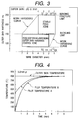
- Fig. 3 diagrammatically shows the relationship between the outer-skin hardness control zone and the hardness of the outer skin of heated and drawn wires 2 to 7 mm in diameter after softening annealing.
- Fig. 4 graphically shows the relationship between the heating time and temperature in a combination of direct electric heating and heating in a tunnel furnace.
- Fig. 5 graphically shows the relationship between the heating time and temperature in heating in a continuous tunnel furnace.
- Fig. 6 graphically shows the relationship between the amount of diffusible hydrogen and the incidence of hydrogen-induced cracking in horizontal-position and fillet welding.
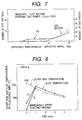
- Fig. 7 graphically shows the relationship between the amount of diffusible hydrogen, the number of pits formed, and the incidence of gas grooves.
- Fig. 8 graphically shows the relationship between the heating time, the temperature of the outer skin of flux-cored wire, and the temperature of flux in Example 1.
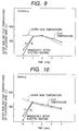
- Fig. 9 graphically shows the relationship between the heating time, the temperature of the outer skin of flux-cored wire, and the temperature of flux in Example 2.
- Fig. 10 graphically shows the relationship between the heating time, the temperature of the outer skin of flux-cored wire, and the temperature of flux in Example 3.
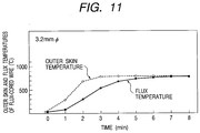
- Fig. 11 is another graph showing the relationship between the heating time, the temperature of the outer skin of flux-cored wire, and the temperature of flux in Example 3.
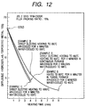
- Fig. 12 graphically shows the relationship between the heating time and the amount of diffusible hydrogen in each example.
- Fig. 1 illustrates the principle of direct electric heating of wire passed through a ring transformer according to this invention.
- a pair of roll electrode units 2 and 3 are disposed with a given space left therebetween and a wire 1 held between facing roll electrodes 2a and 2b and 3a and 3b that make up the roll units 2 and 3.
- the running wire 1 travels forward while maintaining contact with the circumferential surfaces of the paired roll electrodes 2a and 2b and 3a and 3b.
- a ring transformer 4 is concentrically disposed between the paired roll electrode units 2 and 3 so that the wire passes through an opening therein.
- This transformer comprises, for example, an iron core made up of hollow square sheets of electrical steel having ideal properties for forming a magnetic path, that are layered to a desired thickness, with a vacant square opening formed in the center.
- the transformer 4 has a primary coil 5 of long wire wound around each of the four sides positioned 90 degrees apart from the adjoining ones. Both ends of the primary coil 5 are connected to a power supply E.
- the roll electrodes 2 and 3 are electrically connected by means of a conductive member 6. The connecting ends of the conductive member 6 are slidably held in contact with the roll electrodes through sliders 7.
- the cross-sectional area and material of the conductive member 6 can be selected as desired, it is easy to keep the ratio of the electric resistance R 1 of the wire heated to the electric resistance R 2 of the conductive member as R 1 >>R 2 .
- the electric current passing through the circuit rapidly and efficiently heats the wire to as high a temperature as 1100 °C. While the incidence of spark generation is low, the power efficiency is as high as 90 to 95 percent as against approximately 50 percent in high-frequency induction heating. Because the impedance of the secondary side can be kept lower than that of the primary side, voltage variations are small. With the voltage of the supplied power consumed for the heating of the wire between the first and second roll electrode units, the first and second roll electrode units have substantially equal electric potentials. Because the first and second roll electrode units can therefore be grounded, electric current does not leak outside from between the first and second roll electrode units. Besides, the roll electrode units spaced not more than 2 to 5 m apart are conducive to the compact construction of the heating device.
- This rapid direct electric heating through a ring transformer can be applied for simultaneous or separate attainment of optimum dehydrogenation and outer-skin softening.
- dehydrogenation heating to between 620 and 1100 °C is done in an earlier stage to decrease the quantity of diffusible hydrogen.
- Outer-skin softening heating to between 600 and 800 °C done in a later stage controls the hardness of the outer skin (to improve the feed speed and prevent the breaking of the wire). If dehydrogenation in the earlier stage is done on larger-diameter wires that move more slowly, subsequent drawing and surface treatment will suffice to obtain the desired product. Hence, it is preferable to apply dehydrogenation on larger-diameter wires between 8 and 15 mm in diameter.
- a combination of dehydrogenation on larger-diameter wires between 8 and 15 mm in diameter and subsequent heating on reduced wires 2 to 7 mm in diameter which is intended mainly for the softening of the outer skin but accomplishes some additional dehydrogenation, permits continuous efficient manufacture of ultra-low hydrogen welding wires containing not more than 3 ml diffusible hydrogen from only lightly dried bonded flux.
- Fig. 2 shows the relationship between the hardness of the outer skin of wires 8 to 15 mm in diameter and the outer skin hardness control zone after softening annealing
- Fig. 3 shows the relationship between the hardness of the outer skin of wires drawn to 2 to 7 mm in diameter after heating and the outer skin hardness control zone after softening heating.
- the stable feed zone differs between wires 8 to 15 mm in diameter and wires 2 to 7 mm in diameter.
- the wire feeder and the welding point are several meters or tens of meters apart and connected by a flexible conduit. When the flexible conduit is forcibly bent to meet the condition of the work site, as in the welding of bent wiring in a confined space, a great resistance built up between the inner wall of the flexible conduit and the passing wire destabilizes the feed of the wire.
- Fig. 4 shows the relationship between the heating time and temperature in a process combining direct electric heating and heating in a tunnel furnace.
- direct electric heating rapidly raises the outer skin temperature to 800 °C.
- the temperature of the portion of the flux in contact with the inner surface of the outer skin rises to 400 °C and further along the flux temperature curve A.
- the temperature in the central portion of the flux rises along the flux temperature curve B with some time lag, reaching substantially the same level as the outer skin temperature in approximately 5 minutes.
- Fig. 5 shows the relationship between the heating time and temperature in a heating process employing a continuous tunnel furnace. Unlike the case shown in Fig. 4, the outer skin temperature gradually rises to 800 °C in 2 to 3 minutes.
- the flux temperature also rises slowly to 800 °C in approximately 8 minutes.
- direct electric heating permits a rapid heating to a high temperature, an in-line continuous heating by directly connecting several processes, and a heating of wires with larger diameters or thinner outer skins, with high thermal efficiency.
- Fig. 6 shows the relationship between the quantity of diffusible hydrogen and hydrogen-induced cracking in horizontal and fillet welding.
- this figure shows the relationship between the quantity of diffusible hydrogen contained in 100 g deposited metal and the tensile strength of the weld metal.
- the content of diffusible hydrogen is 5 ml
- the tensile strength of the weld metal drops sharply to 60 kgf/mm 2 .
- the content exceeds 7 ml the tensile strength falls to 50 kgf/mm 2 and the likelihood of hydrogen-induced fracture increases. Accordingly, it is preferable to keep the content of diffusible hydrogen in 100 g deposited metal under 5 ml.
- Fig. 7 shows the relationship between the amount of diffusible hydrogen. the number of pits formed, and the incidence of gas grooves (i.e.. primer-proof quality).
- the deposited metal is the metal obtained by applying horizontal fillet welding to steel plate coated with a 20 um thick inorganic zinc primer
- the amount of diffusible hydrogen is the content in 100 g deposited metal
- the number of pits and the incidence of gas grooves are the values in a 50 cm long weld bead.
- the number of pits and the incidence of gas grooves have a tendency to increase sharply when the content of diffusible hydrogen exceeds 10 ml.
- the preferable flux packing ratio for the seamless flux-cored welding wires according to this invention is 10 to 26 percent.
- a 21 mm diameter raw wire filled with flux to 15 percent (by weight) of the internal cavity for seamless flux-cored welding wire according to JIS Z 3313 YFW-C50DR was subjected to a drawing to reduce the diameter to 10 mm so that the internal cavity is filled with flux to 100 percent or more (by bulk density).
- the 10 mm diameter wire was directly electrically heated to 1080 °C at a rate of 72 °C per second by passing the wire, at a speed of 20 m per minute, through a ring transformer disposed between the first and second roll electrode units that are spaced 5 m apart.
- Fig. 8 shows the relationship between the temperatures of the outer skin and the flux. To be more specific, Fig.
- FIG. 8 shows the relationship between the heating time and the temperatures of the outer skin of the flux-cored wire and the flux.
- the outer skin temperature rapidly rose to 1080 °C and the temperature of the portion of the flux in contact with the inner surface of the outer skin rose to 300 °C and further along the flux temperature curve A.
- the temperature in the central portion of the flux rose along the flux temperature curve B with some time lag, reaching approximately 950 °C in 1 minute, as shown in Fig. 8.
- the heated wire was air-cooled with a coefficient of heat transfer of 50 kcal/m 2 h°C for 4 minutes and then water-cooled to below 500 °C by a rapid controlled cooling at a rate of 2.4 °C per second.
- the wire was then subjected to a drawing and surface-treatment process to obtain a finished wire 2.4 mm in diameter.
- the 2.4 mm diameter wire thus obtained was used in welding with a current of 550 amperes at 42 volts, a welding speed of 35 cm per minute, a wire extension of 30 mm, and a carbon dioxide evolution of 30 liters per minute.
- the resulting content of diffusible hydrogen per 100 g deposited metal determined by gas chromatography was 4.2 ml.
- a 21.5 mm diameter raw wire filled with flux to 18 percent (by weight) of the internal cavity for seamless flux-cored welding wire according to JIS Z 3313 YFW-C50DR was subjected to a drawing and surface-treatment process to reduce the diameter to 10.5 mm so that the internal cavity is filled with flux to 100 percent or more (by bulk density).
- the 10.5 mm diameter wire was directly electrically heated to 800 °C at a rate of 53 °C per second by passing the wire, at a speed of 20 m per minute, through a ring transformer disposed between the first and second roll electrode units that are spaced 5 m apart.
- Fig. 9 shows the relationship between the temperatures of the outer skin and the flux. To be more specific, Fig.
- the heated wire was further heated at 800 °C for 2 minutes in a directly connected gas or continuous heating furnace, air-cooled with a coefficient of heat transfer of 50 kcal/m 2 h°C for 2 minutes and then water-cooled to below 500 °C by a rapid controlled cooling at a rate of 2.5 °C per second.
- the wire was then subjected to a drawing and surface-treatment process to obtain a finished wire 2.0 mm in diameter.
- the 2.0 mm diameter wire thus obtained was used in welding with a current of 500 amperes at 38 volts, a welding speed of 35 cm per minute, a wire extension of 25 mm, and a carbon dioxide evolution of 25 liters per minute.
- the resulting content of diffusible hydrogen per 100 g deposited metal determined by gas chromatography was 4.5 ml.
- a 21 mm diameter raw wire filled with flux to 12 percent (by weight) of the internal cavity for seamless flux-cored welding wire according to JIS Z 3313 YFW-C50DR was subjected to a drawing to reduce the diameter to 10 mm so that the internal cavity is filled with flux to 100 percent or more (by bulk density).
- the 10 mm diameter wire was directly electrically heated to 880 °C at a rate of 350 °C per second by passing the wire, at a speed of 60 m per minute, through a ring transformer disposed between the first and second roll electrode units that are spaced 2.5 m apart.
- Fig. 10 shows the relationship between the temperatures of the outer skin and the flux. To be more specific, Fig.
- FIG. 10 shows the relationship between the heating time and the temperatures of the outer skin of the flux-cored wire and the flux.
- the outer skin temperature rapidly rose to 880 °C and the temperature of the portion of the flux in contact with the inner surface of the outer skin rose to 200 °C and further along the flux temperature curve A.
- the temperature in the central portion of the flux rose along the flux temperature curve B with some time lag, reaching approximately 800 °C in 1 minute, as shown in Fig. 10.
- the heated wire was air-cooled with a coefficient of heat transfer of 20 kcal/m 2 h°C for 4 minutes and then water-cooled to below 500 °C by a rapid controlled cooling at a rate of 1.6 °C per second.
- Fig. 11 shows the relationship between the temperatures of the outer skin and flux obtained. To be more specific, Fig. 11 shows the relationship between the heating time and the temperatures of the outer skin and flux of the flux-cored welding wire. As shown in Fig. 11, the outer skin temperature rose to 800 °C in 3 minutes. The flux temperature also rose to approximately 800 °C in 6 minutes. The heated wire was then air-cooled again with a coefficient of heat transfer of 80 kcal/m 2 h°C for 3 minutes and then water-cooled to below 400 °C by a rapid controlled cooling at a rate of 2.2 °C per second.
- the wire was then subjected to a drawing and surface-treatment process to obtain a finished wire 1.2 mm in diameter.
- the 1.2 mm diameter wire thus obtained was used in welding with a current of 270 amperes at 30 volts, a welding speed of 35 cm per minute, a wire extension of 20 mm, and a carbon dioxide evolution of 25 liters per minute.
- the resulting content of diffusible hydrogen per 100 g deposited metal determined by gas chromatography was 2.1 ml.
- Fig. 12 shows the relationship between he heating time and the quantity of diffusible hydrogen in each example.
- the quantity of diffusible hydrogen in 100 g deposited metal was 4.2 ml in Example 1, 4.5 ml in Example 2, 5.0 ml in the wire directly electrically heated to 880 °C and water-cooled to 500 °C after air-cooling and 2.1 ml in the wire further heated in the tunnel furnace and cooled in Example 3.
- all of the wires prepared by the process of this invention contained much less diffusible hydrogen than the conventional ones that were prepared for the purpose of comparison without heating.
- the processes according to this invention thus permit efficient manufacture of low-hydrogen flux-cored welding wires with excellent cracking resistance and primer proof quality suited for the welding of high-tensile and structural steels by reducing the content of diffusible hydrogen.
Landscapes
- Chemical & Material Sciences (AREA)
- Engineering & Computer Science (AREA)
- Mechanical Engineering (AREA)
- Physics & Mathematics (AREA)
- Thermal Sciences (AREA)
- Crystallography & Structural Chemistry (AREA)
- Materials Engineering (AREA)
- Metallurgy (AREA)
- Organic Chemistry (AREA)
- Nonmetallic Welding Materials (AREA)
Priority Applications (2)
| Application Number | Priority Date | Filing Date | Title |
|---|---|---|---|
| US08/798,929 US5821500A (en) | 1997-02-11 | 1997-02-11 | Process for manufacturing welding wire |
| EP97102450A EP0858860A1 (fr) | 1997-02-11 | 1997-02-14 | Procédé de fabrication d'un fil de soudage |
Applications Claiming Priority (2)
| Application Number | Priority Date | Filing Date | Title |
|---|---|---|---|
| US08/798,929 US5821500A (en) | 1997-02-11 | 1997-02-11 | Process for manufacturing welding wire |
| EP97102450A EP0858860A1 (fr) | 1997-02-11 | 1997-02-14 | Procédé de fabrication d'un fil de soudage |
Publications (1)
| Publication Number | Publication Date |
|---|---|
| EP0858860A1 true EP0858860A1 (fr) | 1998-08-19 |
Family
ID=26145238
Family Applications (1)
| Application Number | Title | Priority Date | Filing Date |
|---|---|---|---|
| EP97102450A Withdrawn EP0858860A1 (fr) | 1997-02-11 | 1997-02-14 | Procédé de fabrication d'un fil de soudage |
Country Status (2)
| Country | Link |
|---|---|
| US (1) | US5821500A (fr) |
| EP (1) | EP0858860A1 (fr) |
Families Citing this family (11)
| Publication number | Priority date | Publication date | Assignee | Title |
|---|---|---|---|---|
| US6365864B1 (en) * | 2000-04-26 | 2002-04-02 | Lincoln Global, Inc. | Cleaning device for welding wire and method of cleaning welding wire |
| KR100359482B1 (ko) * | 2000-06-28 | 2002-10-31 | 고려용접봉 주식회사 | 송급성이 우수한 아크용접용 와이어 및 와이어의 신선방법 |
| KR100436487B1 (ko) * | 2002-03-04 | 2004-06-22 | 고려용접봉 주식회사 | 탄산가스 아크용접용 무도금 솔리드와이어 |
| JP3959380B2 (ja) * | 2003-08-28 | 2007-08-15 | 株式会社神戸製鋼所 | シーム有りフラックス入り溶接用ワイヤの製造方法 |
| US7807948B2 (en) * | 2005-05-16 | 2010-10-05 | Lincoln Global, Inc. | Cored welding electrode and method of manufacturing the same |
| US8519303B2 (en) | 2005-05-19 | 2013-08-27 | Lincoln Global, Inc. | Cored welding electrode and methods for manufacturing the same |
| US20070051716A1 (en) * | 2005-09-06 | 2007-03-08 | Lincoln Global, Inc. | Process for manufacturing packaged cored welding electrode |
| FR2897549B1 (fr) * | 2006-02-20 | 2009-02-06 | Air Liquide | Procede de fabrication de tubes remplis de poudres, tels des fils fourres de soudage |
| US20100084388A1 (en) * | 2008-10-06 | 2010-04-08 | Lincoln Global, Inc. | Welding electrode and method of manufacture |
| US8395071B2 (en) | 2010-04-02 | 2013-03-12 | Lincoln Global, Inc. | Feeding lubricant for cored welding electrode |
| JP6048783B2 (ja) * | 2011-09-29 | 2016-12-21 | 高周波熱錬株式会社 | 太陽電池用リード線の製造方法及び設備 |
Citations (8)
| Publication number | Priority date | Publication date | Assignee | Title |
|---|---|---|---|---|
| GB1324651A (en) * | 1969-08-14 | 1973-07-25 | Murex Welding Processes Ltd | Method of producing welding consumables |
| JPS5686699A (en) * | 1979-12-17 | 1981-07-14 | Nippon Steel Corp | Production of wire incorporating stainless steel flux for gas shield arc welding |
| JPS58110195A (ja) * | 1981-12-22 | 1983-06-30 | Kobe Steel Ltd | ステンレス鋼用フラツクス入りワイヤの製造法 |
| JPS5961597A (ja) * | 1982-09-30 | 1984-04-07 | Nippon Steel Weld Prod & Eng Co Ltd | 溶接用フラツクス入りワイヤの製造方法 |
| JPS59130698A (ja) * | 1983-01-14 | 1984-07-27 | Nippon Steel Corp | ステンレス鋼フラツクス入りワイヤの製造方法 |
| JPS63203297A (ja) * | 1987-02-18 | 1988-08-23 | Nippon Steel Corp | ア−ク溶接用クロ−ズドシ−ムワイヤの製造方法 |
| JPH0481297A (ja) * | 1990-07-24 | 1992-03-13 | Kawasaki Steel Corp | 溶接用フラックス入りワイヤの製造方法 |
| EP0489167A1 (fr) * | 1990-06-21 | 1992-06-10 | NIPPON STEEL WELDING PRODUCTS & ENGINEERING CO., Ltd. | Procede de fabrication de tube rempli de matiere en poudre et en grains |
Family Cites Families (4)
| Publication number | Priority date | Publication date | Assignee | Title |
|---|---|---|---|---|
| FR2271898B1 (fr) * | 1974-05-22 | 1977-03-11 | Arbed | |
| JP2816680B2 (ja) * | 1987-11-30 | 1998-10-27 | 高周波熱錬 株式会社 | 帯材通電加熱装置 |
| GB8815371D0 (en) * | 1988-06-28 | 1988-08-03 | Beta Instr Co | Method & apparatus for heating metallic elongated product in motion |
| JPH0581648A (ja) * | 1991-09-24 | 1993-04-02 | Sony Corp | 磁気記録媒体 |
-
1997
- 1997-02-11 US US08/798,929 patent/US5821500A/en not_active Expired - Fee Related
- 1997-02-14 EP EP97102450A patent/EP0858860A1/fr not_active Withdrawn
Patent Citations (8)
| Publication number | Priority date | Publication date | Assignee | Title |
|---|---|---|---|---|
| GB1324651A (en) * | 1969-08-14 | 1973-07-25 | Murex Welding Processes Ltd | Method of producing welding consumables |
| JPS5686699A (en) * | 1979-12-17 | 1981-07-14 | Nippon Steel Corp | Production of wire incorporating stainless steel flux for gas shield arc welding |
| JPS58110195A (ja) * | 1981-12-22 | 1983-06-30 | Kobe Steel Ltd | ステンレス鋼用フラツクス入りワイヤの製造法 |
| JPS5961597A (ja) * | 1982-09-30 | 1984-04-07 | Nippon Steel Weld Prod & Eng Co Ltd | 溶接用フラツクス入りワイヤの製造方法 |
| JPS59130698A (ja) * | 1983-01-14 | 1984-07-27 | Nippon Steel Corp | ステンレス鋼フラツクス入りワイヤの製造方法 |
| JPS63203297A (ja) * | 1987-02-18 | 1988-08-23 | Nippon Steel Corp | ア−ク溶接用クロ−ズドシ−ムワイヤの製造方法 |
| EP0489167A1 (fr) * | 1990-06-21 | 1992-06-10 | NIPPON STEEL WELDING PRODUCTS & ENGINEERING CO., Ltd. | Procede de fabrication de tube rempli de matiere en poudre et en grains |
| JPH0481297A (ja) * | 1990-07-24 | 1992-03-13 | Kawasaki Steel Corp | 溶接用フラックス入りワイヤの製造方法 |
Non-Patent Citations (6)
| Title |
|---|
| PATENT ABSTRACTS OF JAPAN vol. 005, no. 158 (M - 091) 12 October 1981 (1981-10-12) * |
| PATENT ABSTRACTS OF JAPAN vol. 007, no. 215 (M - 244) 22 September 1983 (1983-09-22) * |
| PATENT ABSTRACTS OF JAPAN vol. 008, no. 166 (M - 314) 2 August 1984 (1984-08-02) * |
| PATENT ABSTRACTS OF JAPAN vol. 008, no. 258 (M - 340) 27 November 1984 (1984-11-27) * |
| PATENT ABSTRACTS OF JAPAN vol. 016, no. 299 (M - 1274) 2 July 1992 (1992-07-02) * |
| SUZUKI TOMOYUKI ET AL: "MANUFACTURE OF FLUX-FILLED WIRES FOR ARC WELDING", CHEMICAL ABSTRACTS + INDEXES, vol. 110, no. 10, 6 March 1989 (1989-03-06), pages 312, XP000017233 * |
Also Published As
| Publication number | Publication date |
|---|---|
| US5821500A (en) | 1998-10-13 |
Similar Documents
| Publication | Publication Date | Title |
|---|---|---|
| US5821500A (en) | Process for manufacturing welding wire | |
| US6079243A (en) | Method of production of welding wire | |
| US6492036B2 (en) | Porous electrode wire for use in electrical discharge machining and method of manufacturing the same | |
| US6180920B1 (en) | Electrode and method of making same | |
| US1892607A (en) | Method for making a tube | |
| KR101630309B1 (ko) | 땜납 도금선의 제조방법 및 제조장치 | |
| CN1102480C (zh) | 焊丝制造工艺 | |
| US3421925A (en) | Method for producing improved metallic strip material | |
| US2092018A (en) | Method of making tubes and copper coating process | |
| KR100380664B1 (ko) | 용접 와이어의 제조방법 | |
| US611222A (en) | Method of and means for manufacturing metal tubing | |
| HK51688A (en) | Process for producing soldered, multi-layer metal tubes, and apparatus for carrying out this process | |
| JPH0957489A (ja) | 溶接用ワイヤの製造方法 | |
| KR20060051243A (ko) | 가스 금속 아크 용접용 용접 와이어 전극 | |
| US3673374A (en) | Surface metal welding process and apparatus | |
| JPH11197878A (ja) | ガスシールドアーク溶接用ワイヤおよびその製造方法 | |
| US2084268A (en) | Tube making and copper coating process | |
| JPH023679B2 (fr) | ||
| JPH08252691A (ja) | ガスシールドアーク溶接用ワイヤ | |
| GB2106427A (en) | The manufacture of mineral insulated cables | |
| US3573118A (en) | Methods and apparatus for handling wire rod | |
| US2983808A (en) | Electric arc welding | |
| JPH09150292A (ja) | ガスシールドアーク溶接用ワイヤ | |
| US1916014A (en) | Welding process | |
| KR20250052949A (ko) | 복합 변질제 피복심선 |
Legal Events
| Date | Code | Title | Description |
|---|---|---|---|
| PUAI | Public reference made under article 153(3) epc to a published international application that has entered the european phase |
Free format text: ORIGINAL CODE: 0009012 |
|
| AK | Designated contracting states |
Kind code of ref document: A1 Designated state(s): DE FR GB IT SE |
|
| 17P | Request for examination filed |
Effective date: 19981029 |
|
| AKX | Designation fees paid |
Free format text: DE FR GB IT SE |
|
| RBV | Designated contracting states (corrected) |
Designated state(s): DE FR GB IT SE |
|
| STAA | Information on the status of an ep patent application or granted ep patent |
Free format text: STATUS: THE APPLICATION HAS BEEN WITHDRAWN |
|
| 18W | Application withdrawn |
Withdrawal date: 20000615 |