EP0858897A1 - Imageur a encre - Google Patents
Imageur a encre Download PDFInfo
- Publication number
- EP0858897A1 EP0858897A1 EP96935349A EP96935349A EP0858897A1 EP 0858897 A1 EP0858897 A1 EP 0858897A1 EP 96935349 A EP96935349 A EP 96935349A EP 96935349 A EP96935349 A EP 96935349A EP 0858897 A1 EP0858897 A1 EP 0858897A1
- Authority
- EP
- European Patent Office
- Prior art keywords
- light receiving
- ink
- output
- receiving elements
- image forming
- Prior art date
- Legal status (The legal status is an assumption and is not a legal conclusion. Google has not performed a legal analysis and makes no representation as to the accuracy of the status listed.)
- Granted
Links
Images













Classifications
-
- B—PERFORMING OPERATIONS; TRANSPORTING
- B41—PRINTING; LINING MACHINES; TYPEWRITERS; STAMPS
- B41J—TYPEWRITERS; SELECTIVE PRINTING MECHANISMS, i.e. MECHANISMS PRINTING OTHERWISE THAN FROM A FORME; CORRECTION OF TYPOGRAPHICAL ERRORS
- B41J25/00—Actions or mechanisms not otherwise provided for
- B41J25/304—Bodily-movable mechanisms for print heads or carriages movable towards or from paper surface
-
- B—PERFORMING OPERATIONS; TRANSPORTING
- B41—PRINTING; LINING MACHINES; TYPEWRITERS; STAMPS
- B41J—TYPEWRITERS; SELECTIVE PRINTING MECHANISMS, i.e. MECHANISMS PRINTING OTHERWISE THAN FROM A FORME; CORRECTION OF TYPOGRAPHICAL ERRORS
- B41J2/00—Typewriters or selective printing mechanisms characterised by the printing or marking process for which they are designed
- B41J2/005—Typewriters or selective printing mechanisms characterised by the printing or marking process for which they are designed characterised by bringing liquid or particles selectively into contact with a printing material
- B41J2/01—Ink jet
-
- B—PERFORMING OPERATIONS; TRANSPORTING
- B41—PRINTING; LINING MACHINES; TYPEWRITERS; STAMPS
- B41J—TYPEWRITERS; SELECTIVE PRINTING MECHANISMS, i.e. MECHANISMS PRINTING OTHERWISE THAN FROM A FORME; CORRECTION OF TYPOGRAPHICAL ERRORS
- B41J2/00—Typewriters or selective printing mechanisms characterised by the printing or marking process for which they are designed
- B41J2/005—Typewriters or selective printing mechanisms characterised by the printing or marking process for which they are designed characterised by bringing liquid or particles selectively into contact with a printing material
- B41J2/01—Ink jet
- B41J2/21—Ink jet for multi-colour printing
-
- B—PERFORMING OPERATIONS; TRANSPORTING
- B41—PRINTING; LINING MACHINES; TYPEWRITERS; STAMPS
- B41J—TYPEWRITERS; SELECTIVE PRINTING MECHANISMS, i.e. MECHANISMS PRINTING OTHERWISE THAN FROM A FORME; CORRECTION OF TYPOGRAPHICAL ERRORS
- B41J29/00—Details of, or accessories for, typewriters or selective printing mechanisms not otherwise provided for
- B41J29/38—Drives, motors, controls or automatic cut-off devices for the entire printing mechanism
- B41J29/393—Devices for controlling or analysing the entire machine ; Controlling or analysing mechanical parameters involving printing of test patterns
Definitions
- the present invention relates to an ink-type image forming device and particularly to such a device which includes a plurality of recording heads for multi-color printing.
- An ink-jet system one of ink recording systems, is a system in which a nozzle, filled with ink derived from an ink container, includes a heater which is driven with a pulse signal for heating the nozzle to eject an ink drop by the pressure of an air bubble that is created in the ink by the heating.
- an image is formed using a recording head which is constituted by a plurality of nozzles aligned in line.
- a recording head 3 (heareinafter referred to as only "head") mounted on a carriage is moved in a main-scanning direction (X) to successively print a multiple of columns 17 one by one on a sheet of paper 15 to form one band of an image. Then, the paper sheet 15 is moved in a sub-scanning direction (Y) to form a second band of the image which adjoins the first band.
- a plurality of recording heads are used which eject ink drops of different colors, e.g., cyan C, magenta M, yellow Y and black K, to perform a printing with the colors overlapped with each other.
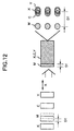
- misalignment or deviation D1 in relative position of the plurality of heads could be present among the heads in a lateral or main-scanning direction. Such deviation D1 will cause a vertical stripe pattern in a printed image.
- Figure 12 shows an example in which only the head of magenta M is misaligned leftward by an amount D1 with respect to other heads.
- deviation D2 in a vertical or sub-scanning direction could also be present among the plurality of heads.
- Such deviation D2 will cause a horizontal stripe pattern to appear in a printed image.
- Figure 13 shows an example in which only the head of magenta M is misaligned downward by an amount D2 with respect to other heads.
- the deviation among the heads could degrade a printed image.
- an ink-type image forming device which synchronizes the ejection of ink drops by using a linear scale 301, which has slits 303 regularly provided therealong for every dot position, and a linear sensor 302, which is movable along the linear scale 301 to detect the presence/absence of the slits at any position thereof, as shown in Figure 14 to eject ink drops at accurate points corresponding to individual positions in the main-scanning direction of the heads.
- This type of image forming device when performing a bi-directional (or two-way) printing in which printing is made in both forward and backward paths of the heads moving along the main-scanning direction, as shown in Figure 15(a), in the forward path a delay time d1 is created from the detection of a slit to the actual ejection of an ink drop whereas in the backward path a delay time d2 is similarly created. Thus, the sum of the delay times makes (d1+d2). The sum of the delay times (d1+d2) could degrade a printed image because of the deviations (D5) of ejected positions of ink drops between the forward and backward paths in spite of attempting to print dots at the same position P. The image degradation is significant especially when printing a line drawing. For example, as shown in Figure 15(b), when ideally one vertical line 151 is to appear, two parallel dashed lines 12 would be printed.
- the configuration of a head is classified into two types: an integrated type in which an ink container is integrated with an associated head as shown in Figure 16(b) and a separate type in which a head 3 is separate from an ink container 3' as shown in Figure 16(a).
- the integrated type recording heads are handled as consumable supplies which are exchanged arbitrarily by a user when the ink container runs short of ink. Therefore, each time of the exchange of a head, alignment of the head should be checked and, if any, corrected.
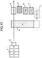
- a vertically elongated rectangular region a (referred to as a reference region hereinafter) is recorded with a head of a particular color (black in this case), which acts as a reference for alignment in position, while successively recording a black region b , a cyan region c , a magenta region d , and a yellow region e (referred to as compared regions hereinafter), respectively at instructed positions laterally spaced away from the reference region, in the order mentioned from the upper to the lower.
- regions a to e are all printed in the same direction (here from left to right). Regarding the regions b to e , some of them which have deviation of the heads would not be aligned with other regions, despite of intending to print the regions at aligned positions. It is shown in the illustrated example that the cyan head has a misalignment error, resulting in a lateral shift of the region c relative to the other regions.
- the region a is printed vertically lengthened as shown by a dashed line in Figure 17.
- an additional region f is printed with the head of the same color (black) as the region a at the same lateral position as the regions b to e .
- Only the region f is printed in the reverse direction (from right to left). It is found that due to the above-mentioned delay d1 + d2, the region f is shifted leftward with respect to the region b of the same color.
- the print pattern shown in Figure 17 is detected by a sensor 9 which is mounted on the carriage near the head and optically reads the pattern to calculate the amounts of deviation of each head.
- the deviation of heads is also referred to as a registration error.
- the sensor for detecting the print pattern is constituted by a light emitting element 601, a light receiving element 602 (e.g. a photodiode), and a lens 603.
- Figure 18 (a) and (b) illustrate a front view and a plane view of the sensor, respectively.
- a carriage moving direction main-scanning direction
- a direction perpendicular to the carriage moving direction is indicated by "Y”.
- the light emitted from the light emitting element 601 is projected onto the surface of a paper sheet, and the reflected light is received through the lens 603 by the light receiving element 602.
- the sensor output was current-to-voltage converted by an amplifier circuit 701, amplified by an inverting amplifier circuit 702, and then compared with a predetermined threshold voltage in a comparator 703 to be converted into bi-level digital data, and digitally processed.
- the printed sheet of paper used for detecting the registration errors is not necessarily laid ideally flat, but part or entirety of the sheet could be raised or float at a height D0 (approximately a couple of millimeters).
- D0 approximately a couple of millimeters
- the amplitude of the sensor output will vary between at floating points and at non-floating points of the paper sheet, causing an error in the detection of an edge position of the bi-level output, which could degrade the accuracy in detecting the printed pattern.
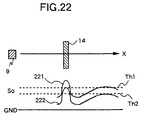
- intermediate paper e.g., tracing paper
- intermediate paper 222 has less light reflected therefrom than normal paper 221 so that it could be impossible to detect the peak of the sensor output So, which corresponds to the printed region 14, because of the insufficient light loser than a threshold level Th1.
- the threshold level for bi-level digitization should be changed to a lower level Th2 depending upon the papers to be used.
- an ink type image forming device on which a plurality of recording heads are mounted and moved so that an age is formed on a recording medium
- said device comprising: a test pattern printing means for printing a predetermined test pattern on a recording medium by the use of the plurality of recording heads; a reading means for reading the test pattern printed by said test pattern printing means by optically scanning the test pattern; a mounting-position-error detection means for detecting deviations in position of the recording heads with respect to a reference one of the plurality of recording heads, based on reading results of the reading means; said reading means including a light emitting element for emitting light on the recording medium, and first and second light receiving elements for receiving light reflected from the recording medium, said first and second light receiving elements being spaced apart with each other by a predetermined distance, and said position error detection means including a subtracting means for subtracting an output of one of said first and second light receiving elements from an output of the other, and means for determining the deviations in position on the basis of the subtracted output
- the device comprises a head scanning means for causing the plurality of recording heads to move in a main-scanning direction across the recording medium, and a recording medium travelling means for moving the recording medium in a sub-scanning direction perpendicular to the main-scanning direction, the first and second light receiving elements being disposed substantially at the same distance from the light emitting element and the first and second light receiving elements being aligned along a line which is inclined at a predetermined angle with respect to the recording-head moving direction X (main-scanning direction) and the recording-medium moving direction Y (sub-scanning direction).
- the first and second light receiving elements 21 and 22 are equally spaced from the light emitting element 23, while the common center axis through the light receiving elements 21 and 22 inclines at a predetermined angle (e.g., 45 degrees) with respect to the head moving direction (carriage moving direction or main-scanning direction) and the recording-medium moving direction (paper-travelling direction or sub-scanning direction).
- a predetermined angle e.g. 45 degrees
- the mounting-position-error detection means may include first and second amplifiers for amplifying the outputs of the first and second light receiving elements, respectively, and a gain control means for automatically controlling at least one of the first and second amplifiers so that the outputs of the light receiving elements are at an equal level, with the light emitting element tuned on.
- first and second amplifiers for amplifying the outputs of the first and second light receiving elements, respectively
- a gain control means for automatically controlling at least one of the first and second amplifiers so that the outputs of the light receiving elements are at an equal level, with the light emitting element tuned on.
- the mounting-position-error detection means may include first and second amplifiers for amplifying the outputs of the first and second light receiving elements, respectively, and an automatic offset control means for automatically controlling at least one of reference levels for the first and second amplifiers so that the outputs of the light receiving elements are at an equal level, with the light emitting element tuned off. This enables dealing with the difference between the temperature characteristics of the two light receiving elements.
- Figure 1 is a block diagram which shows an embodiment of the ink type image forming device according to the present invention
- Figure 2 is a perspective view showing an arrangement of respective parts of the device.
- an ink type image forming device generally comprises three parts: an external device 1 including an image scanner, a personal computer, a CAD device, etc., a print control unit 2 and heads 3.
- the ink type image forming device of such a configuration generally operates as follows.
- the print control unit 2 perform a predetermined processing with respect to image data VDI, which is forwarded from the external device 1, and then the heads 3 forms an image on a printing paper sheet based on the result of the processing.
- the print control unit 2 includes a CPU (Central Processing Unit) 4, head control units 5, a pattern detection unit 6, a registration error detection unit 7 for detecting amounts of deviations of respective heads based on the values detected by the pattern detection unit 6, an ROM (Read Only Memory) 18 which stores programs to be executed by the CPU 4 and pattern data to be printed, an image memory 19 for temporarily storing image data.
- the CPU 4 interfaces with the external device 1 which forwards the image data VDI, and controls the entire operation of the print control unit 2 including memories (not shown), I/O devices, etc.
- the heads control units 5, instructed from the CPU 4 Upon receipt of the image data VDI forwarded from the external device 1, the heads control units 5, instructed from the CPU 4, temporarily stores a few bands of the image data VDI in the image memory 19.
- the stored image data VDI are subjected to various image processing and resultant image data VDO are output in synchronism with the scanning of the heads 3.
- the synchronisation for the print control of the image data VDO, etc. is performed by using a signal LINSCL which is generated from a linear scale 8 in synchronism with the scanning of the heads 3.
- the head control unit 5 also creates enable signals BENB0-7 for the respective blocks of each head 3, and pulse signals for driving heaters (i.e., signals necessary for ejecting ink drops).
- each head 3 includes 128 nozzles which are divided into eight blocks, and hence, uses eight block-enable signals.
- the image data VDO, block-enable signals BENB0-7, heater driving pulse signals HENB, etc. outputted from the head control units 5 will be forwarded to the heads 3 where control circuits in the heads 3 drive heaters on for only nozzles whose associated image data VDO and enable signals (BENB, HENB) are enabled, so that ink drops are ejected onto a printing paper sheet to form a column of image. Such a control is repeated while moving the heads 3 in the main-scanning direction so as to form a band of image.
- four heads 3 are used, and corresponding to these heads, four head control units 5 are also used.
- the heads 3 are equipped with integrated type of ink containers of cyan, magenta, yellow and black, respectively, to realize a full-color printing. In the description below, only circuit for one of the sets will be explained.
- An upper-cover open/close detection sensor 10 is mounted on the main body of the device.
- heads 3 are exchanged, and then the upper cover 12 is closed again, an operation is started to detect the registration errors.
- this operation may be commanded with an operation key (not shown) pressed by a user.
- a print pattern test pattern as shown in Figure 17 mentioned above is automatically printed.
- the width of each region of the print pattern along the scanning direction of the sensor 9 is, for example, a few millimeters.
- the data of this print pattern is prestored in the ROM 18. Then, after printing the print pattern, the sensor 9 mounted adjacent to the heads starts to read the printed pattern to detect the registration errors.
- M1 indicates a motor for moving the carriage in the X direction and M2 indicates a motor for travelling the paper sheet 15.
- the senor 9 is mounted on the carriage which carries the heads thereon.
- the sensor 9 may be provided separately from the carriage.
- the sensor 9 scans the regions a and b of the pattern, so that a difference signal SUB of the outputs from the two light receiving elements of the sensor 9 is converted into a bi-level digital signal Bout with a particular threshold voltage Th in the pattern detection unit 6 of the print control unit 2. Based on the bi-level signal Bout, a distance DST between the two regions is obtained in the registration error detection unit 7.
- the distance DST1 between the regions a and b is obtained by counting reference clock CLK during a time from a leading edge of the bi-level signal output Bout, derived from the scanning of the regions a and b , to the subsequent leading edge of the same. With a higher frequency of the reference clock, the registration errors can be detected with a higher resolution.
- each distance between respective two regions is obtained with respect to regions a and d , and regions a and e .
- differences (d0) between the respective data so as to calculate to what extent each head is misaligned relative to a reference head.
- the sign (plus or minus) of the difference d0 shows in which direction the head is shifted, left or right, with respect to the head of the reference color.
- regions a and b are printed with a reference one of the heads and regions c/d/e are printed with other heads.
- the head with a black ink container is used as the reference.
- the regions a/b are printed with the head of the black ink container, the region c with cyan ink, the region d with magenta, and the region e with yellow.
- the region b is illustrated misaligned with the regions c/d/e. This shows an aspect where the regions were intended to be printed at the same reference column, but the printed result ended in the misalined printing due to the lateral shift of a head.
- the carriage mounting the sensor 9 is moved in a main-scanning direction to read the printed pattern.
- the sensor 9 is moved over the printed pattern and then a paper sheet is travelled in a sub-scanning direction to read the printed pattern.
- an additional region f may be provided as shown in Figure 17.
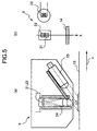
- Figure 5 (a), (b) shows an internal configuration of the sensor 9 which includes first and second light receiving elements 21 and 22, a light emitting element 23, a lens 24, etc.
- the first and second light receiving elements 21 and 22 are equally spaced from the light emitting element 23 and disposed adjacent to each other in the carriage moving direction X (main-scanning direction).
- the fist and second light receiving elements are constituted by a two-divided photodiode, but alternatively two photodiodes of a normal one-chip type may be used.
- a lens of a 5 mm diameter is used and disposed so that the image printed on a paper sheet is focused with a doubled size on each of the light receiving elements 21, 22.
- a light receiving area (hatched in Figure ) of each of the light receiving elements 21, 22 is 1.5 mm x 1.5 mm in size.
- the light receiving elements 21 and 22 receive reflected light from the respective areas each of 0.75 mm x 0.75 mm with a border of a center C disposed therebetween.
- the outputs from the light receiving elements 21, 22 which have read the pattern on a paper sheet will be processed at the pattern detection unit 6 (see Figure 1) to detect portions at which the intensity changes depending upon the pattern.
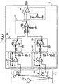
- FIG. 7 A detailed configuration of the pattern detection unit 6 is shown in Figure 7 and its operation waveforms are shown in Figure 8.
- numerals 31 and 32 each indicate a current amplifier circuit
- numerals 33 and 34 each indicate an inverting amplifier circuit
- a numeral 35 indicates a differential amplifier circuit
- a numeral 36 indicates a comparator.
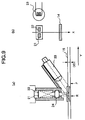
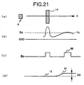
- the light receiving elements 21 and 22 are placed at a distance from each other. Therefore, the outputs from the respective light receiving elements 21 and 22 which have read the pattern on a paper sheet will vary with a difference in time as shown in Figure 8 (b) and (c).
- photodiodes are used as the light receiving elements, and the output waveforms shown in Figure 8 (b) and (c) represent the current-to-voltage converted outputs from the current amplifier circuits 31 and 32 of Figure 7 that convert variation in currents, which are generated in the photodiodes in response to light variations, into voltages when the pattern is read.
- the output from the light receiving elements 21 and 22 are at a faint level, and hence, the current-to-voltage converted outputs from the amplifier circuits 31 and 32 are further amplified at the inverting amplifier circuits 33 and 34, one outputs of which is then subtracted from the other at the differential amplifier circuit 35.
- the subtracted output SUB varies only at the portions where the printed pattern is present, centered at a reference level (GND).
- the two light receiving elements 21 and 22 receive the light reflected from the area of 1.5 mm x 0.75 mm on a paper sheet where the floating amount of the paper sheet has no substantial change within the area (because the area is small). For this reason, even if the paper sheet floats, the resultant change in the output will be very slow. Thus, when the output of the light receiving element 21 is subtracted from that of the light receiving element 22, the outputs will cancel at the floating portions (see Figure (b), (c) and (d)).
- the first and output peaks corresponding to the printed pattern will remain even after the subtraction, in the form of a positive peak 84 and a negative peak 85 (see Figure 8 (d)).
- the light receiving elements are disposed spaced apart from each other in the carriage-moving direction and because the outputs corresponding to the printed pattern regions change abruptly.
- the potions of the printed pattern regions can be accurately detected notwithstanding the presence of the paper sheet floating.
- the sensor output of a paper sheet of a lower reflectance has a lower DC level than that of a paper sheet of a higher reflectance, but their changing components are substantially maintained.
- This enables the output changing only at the portions corresponding to the pattern regions, centered at the reference level (GND) (see Figure 8 (d)), when performing the subtraction between the outputs of the light receiving elements 21 and 22, by the use of the same means as described above. Accordingly, it is possible to accurately detect printed pattern regions even when the printed pattern is formed on a paper sheet of a low reflectance.
- the subtracted output changes only at the portions corresponding to the printed pattern regions so that a bi-level conversion can be performed with a fixed threshold level as described below.
- the output of the differential amplifier circuit 35 is compared, at the comparator 36, with a predetermined threshold level to be converted into a bi-level digital data, which in turn are digitally processed at the registration error detection unit 7 to detect registration errors.
- the two light receiving elements 21 and 22 are disposed at the same distance from the light emitting element 23.
- floating of a paper sheet will change the position illuminated by the light emitting element 23 so that the front side F of the sheet nearer the light emitting element 23 become brighter than the rear side R. This will change the amount of light incident into the respective light receiving elements 21,22, causing a significant change in the subtracted output.
- the light receiving elements 21, 22 are disposed at the same distance from the light emitting element 23, as previously mentioned. This assures that when the outputs of the light receiving elements 21 and 22 change because of the paper sheet floating, they change equally so that the changes are cancelled in the subtracted output.
- the first and second light receiving elements 21 and 22 are used both for reading the pattern for detecting lateral registration errors ( Figure 4 (a)) and the pattern for detecting vertical registration errors ( Figure 4 (b)).
- the light receiving elements 21 and 22 are mounted at 45 degrees relative to the main-scanning axis (carriage-moving direction x) and sub-scanning axis (paper-travelling direction Y).
- a position instructed to eject an ink drop at is corrected by the amount of the error.
- a timing of ejecting the ink drop is made earlier or later depending upon the sign of the error.
- data stored in the image memory 19 may be corrected by the amount corresponding to the error.
- part of the vertically aligned 128 nozzles e.g., 120 nozzles
- these effective nozzles are selected to be displaced by the amount corresponding to the error.
- the method of correcting the printing errors, per se is not directly related to the present invention, and methods other than that may be used.
- the patterns for detecting lateral and vertical registration errors are read to accurately detect the deviations in relative position of heads with a simple control, without being affected by the paper sheet floating and the type of paper sheet, and without a complicated control of compensating for the affections.
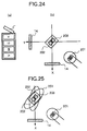
- a printing paper sheet absorbs ink drops during printing, which could cause the sheet to cockle depending upon the printing density or the nature of the paper sheet, affecting the part of the sheet at which the printing is being performed.
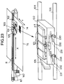
- the carriage 102 on which a head 101 (equivalent to head 3 in the first embodiment) is mounted, is provided with a lever 103 for adjusting the height of the head, as shown in Figure 23.
- a head 101 equivalent to head 3 in the first embodiment
- the carriage 102 on which a head 101 (equivalent to head 3 in the first embodiment) is mounted, is provided with a lever 103 for adjusting the height of the head, as shown in Figure 23.
- stepwise slide grooves 232 Provided at the front face of the carriage 102 is stepwise slide grooves 232, in which pins 231 coupled with the lever 103 are engaged.
- the pins 231 are also coupled to blocks 233.
- the lever 103 When the lever 103 is moved by a user in the X direction, the ganged pins will slide within the stepwise slide grooves so as to change the height of the pins 231. This is followed by the change of the height of the blocks 233, the bottom faces of which contact the front rail 106.
- the carriage 102 is supported at its rear part on the rear rail 104, slidably in the X direction and pivotally about the axis of the rear rail 104. Therefore, by manipulation of the lever 103, the blocks 233 lying on the front rail 106 moves up or down, which will cause the carriage 102 to pivot about the rear rail 104, moving the head upward or downward in the Z direction.
- Such a configuration allows a user to adjust the height of the head 101, and hence, the distance between the head and the paper sheet, in a plurality of steps (here, three steps).
- the sensor 105 (equivalent to the sensor 9 in the first embodiment) will be lifted up similarly with a lift-up of the head 101 because the sensor 105 is fixed to the carriage 102.
- the light receiving elements 202 and 203 are disposed at the same distance from the light emitting element.
- the sensor 105 itself is tilted such that the light receiving elements 202 and 203 are aligned at an angle of 40 degrees with respect to the main-scanning direction (X) and the sub-scanning direction (Y). This is the same as in the first embodiment explained with reference to Figure 10.
- the shape of the light spot 252 formed on the paper sheet from the light emitting element 201 tilts relative to the array of the first and second light receiving elements 202, 203.
- illuminance of the light projected onto a paper sheet is not uniform in the spot, and hence, when a normal spot shape 251 tilts as indicated by the spot shape 252, the lights incident into the light receiving elements may change.
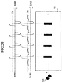
- the subtracted output between the both light receiving elements may be shifted in the positive or negative direction with respect to the reference level (GND) over the entire paper sheet when the head is lifted up (SUB2) as compared to the normal case (SUB 1).
- Such an event as the subtracted result from the outputs of the light receiving elements deviates positively or negatively from the reference level could occur also due to mechanical dispersion in mounting the sensor 105 on the carriage 102 in manufacturing products, non-uniformity of illuminance due to the light emitting element 201, errors in sensitivities of the light receiving elements 202, 203, and dispersion of constants of the amplifier circuits for amplifying the outputs of the light receiving elements.
- FIG. 27 an exemplary configuration of the pattern detection unit 6 in this embodiment is shown in Figure 27 where similar elements are assigned with the same reference symbols as those in Figure 7.
- a variable-gain amplifier 501 an analog-to-digital (A/D) converter 503, a digital-to-analog (D/A) converters 504, 506 are newly provided, and the comparator 36 is replaced with comparators 507 and 508.
- the variable-gain amplifier 501 is configured to amplify the output of one (203 in this case) of the two light receiving elements 202, 203 at an arbitrary gain responsive to an instruction from the CPU 4.
- the light emitting element 201 When a paper sheet is fed in after exchanging a head, or in response to a user's command to correct the registration errors, the light emitting element 201 is automatically turned on, and then, the gain of the variable-gain amplifier 501 is adjusted so as to cause the outputs from the light receiving elements 202, 203 are equalized at the same level. More specifically, the output of the differential amplifier 35 is monitored through the A/D converter 503 by the CPU 4, which in turn adjusts the gain of the variable-gain amplifier 501 through the D/A converter 504 so as to make the output stay at the reference level (GND).
- the light receiving elements 202, 203 have individual temperature characteristics due to the dispersion in manufacturing, which will produce a difference between their output levels as the ambient temperature changes, resulting in a shift of the output of the differential amplifier 35 with respect to the reference level.
- an automatic adjustment is performed so that the outputs from the receiving elements 202, 203, when the light emitting element 201 is in an OFF state, are at the same level. More specifically, similarly to the gain adjustment of the variable-gain amplifier 501, the output of the differential amplifier 35 is monitored through the A/D converter 503 by the CPU 4, which in turn adjusts the reference level of an inverting amplifier in the offset adjusting circuit 34 through the D/A converter 506.
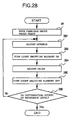
- the carriage 102 is automatically moved above the paper sheet (281), and the offset adjustment is performed in the offset adjusting circuit 34 in a state where the light emitting element 201 remains off (282).
- the differential output is adjusted at the reference level (GND) in the offset adjustment step
- the light emitting element 201 is turned on (283), and the adjustment step for the variable gain amplifier 501 is initiated so as to make the differential output match the reference level (284).
- This gain adjustment will change the gain of the variable-gain amplifier 501, also changing the offset level when the light emitting element 201 is in an OFF state.
- the light emitting element 201 is turned off (285), the level of the differential output is checked (286), and then the offset adjustment step is again performed if the level has changed.
- the foregoing steps are iterated so that the differential output will not change from the reference level even when the light emitting elements 201 is turned on or off. At the time this state is obtained, the detection and correction of the registration errors are started.
- the printed pattern for detection of the registration errors are read and the bi-level conversion is performed at the comparators 507 and 508.
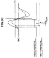
- the sensor output will change in amplitude color by color as shown in Figure 30, because a paper sheet exhibits a different amount of light absorption for each color.
- the difference in sensor amplitude causes the center position of the detected pulse width to be deviated (Dcent). For this reason, simply obtaining a pulse width based on the bi-level output, which is obtained from the differential amplified output by one comparator to obtain the center dot position, could cause the center position to deviate.
- two comparators 507 and 508 are further provided, wherein their reference voltages (Vref1, Vref2) are set positive and negative, respectively, with respect to the reference level (GND). This allows respective bi-level conversions for the positive and negative portions of the output from the differential amplifier 35 so as to obtain the width of a printed region based on the respective bi-level outputs.
- the two bi-level signals are used in the registration error detection unit 7 to obtain widths of respective regions, and then the width data of each region is halved by the CPU 4 to determine the center dot position of the region.
- FIG 31 there is shown an example of internal circuit configuration of the registration error detection unit 7 in the embodiment. The operation of this circuit will be explained below referring to the waveforms as shown in Figure 29.
- a leading edge of the bi-level signal (Bo1), which has been derived from the positive portion of the output SUB of the differential amplifier 35 is detected with a reference clock (CLK) at flip-flops 901, 902 and an AND circuit 903, and a trailing edge of the bi-level signal (Bo2), which has been derived from the negative portion of the output SUB of the differential amplifier 35 is detected at flip-flops 904, 905 and an AND circuit 906.
- a J-K flip-flop 907 generates a signal (AW) which has an enabling (effective) period between the two edges. This is a signal which indicates the width of a region.
- a load signal (LD) to operate an up-down counter 910 is generated by a flip-flop 908 and an AND circuit 909.
- the up-down counter 910 is loaded with input data and performs up-counting during the enabled period of the signal PW.
- B input is selected as an input to a selector 918 so that a value 0 (HEX) is input to start the counting with 0.
- the count of the counter 910 is read in response to the outputs from AND circuits 911, 913, 914 and a flip-flop 912. In each scanning of the sensor, a pair of the reference region and a compared region are read.
- the AND circuits 913, 914 generate sampling signals to cause latch circuits 915, 916 to hold width data of the respective regions. Subsequently, the CPU 4 reads data out of the latch circuits 915 and 916 and halves the read-out data to calculate the half value of the width of the region.
- a width DST (described below) between the center dots can always stably be obtained because the center dot position will not change even if the amplitude of the sensor output varies color by color.
- the calculated data are selected at a selector 917.
- the up-down counter 910 and the selector 918 are set for a down counting operation (AW/DST is set low "L"), and again, the same regions are scanned so that a borrow signals is output from the borrow output (BO) of the up-down counter 910 at each center dot position of the two regions.
- This borrow signal is a timing signal CENTDT which indicates a center dot position of each region.
- a flip-flop 919 With this signal, a flip-flop 919 generates a signal DST which indicates the duration between the center dots of the regions, during which a counter 920 counts the width between the center dots. After completion of the count operation, the width data is read by CPU 4. This data is data D1 between the center dots of the regions a ⁇ b as shown in Figure 29.
- a CPU interface circuit 921 is provided to interconnect the CPU 4 between the selectors 917, 918, the up-down counter 910, the latch circuits 915, 916, and the counter 920.
- the first and second light receiving elements are provided together with the subtraction means for subtracting one of the outputs of the first and second light receiving elements from the other, so that the outputs corresponding to floating portions of a paper sheet are cancelled, thereby accurately detecting the presence of each region of the printed pattern because of the time difference between the outputs corresponding to the printed pattern region.
- the first and second light receiving elements are equally spaced from the light emitting element while their common center axis being tilted at an angle relative to the recording head-moving direction (main-scanning direction) and the recording medium-moving direction (sub-scanning direction), thereby accurately detecting the printed pattern regions for both of the main- and sub-scanning directions.
- the present invention is preferably applicable to an image forming device of an ink type such as the ink jet, in which separate heads for plural colors of ink are mounted to perform a full-color printing.
Landscapes
- Ink Jet (AREA)
- Character Spaces And Line Spaces In Printers (AREA)
Applications Claiming Priority (4)
| Application Number | Priority Date | Filing Date | Title |
|---|---|---|---|
| JP26995795 | 1995-10-18 | ||
| JP26995795 | 1995-10-18 | ||
| JP269957/95 | 1995-10-18 | ||
| PCT/JP1996/003005 WO1997014563A1 (fr) | 1995-10-18 | 1996-10-17 | Imageur a encre |
Publications (3)
| Publication Number | Publication Date |
|---|---|
| EP0858897A1 true EP0858897A1 (fr) | 1998-08-19 |
| EP0858897A4 EP0858897A4 (fr) | 1999-09-22 |
| EP0858897B1 EP0858897B1 (fr) | 2003-04-09 |
Family
ID=17479579
Family Applications (1)
| Application Number | Title | Priority Date | Filing Date |
|---|---|---|---|
| EP96935349A Expired - Lifetime EP0858897B1 (fr) | 1995-10-18 | 1996-10-17 | Imageur a encre |
Country Status (5)
| Country | Link |
|---|---|
| US (1) | US6084607A (fr) |
| EP (1) | EP0858897B1 (fr) |
| JP (1) | JP3313119B2 (fr) |
| DE (1) | DE69627364T2 (fr) |
| WO (1) | WO1997014563A1 (fr) |
Cited By (6)
| Publication number | Priority date | Publication date | Assignee | Title |
|---|---|---|---|---|
| EP0974468A3 (fr) * | 1998-07-21 | 2000-06-07 | Canon Kabushiki Kaisha | Procédé d'ajustement de la position de l'impression par points et appareil d'impression |
| EP0995607A3 (fr) * | 1998-10-23 | 2000-11-22 | Canon Kabushiki Kaisha | Appareil d'impression et procédé de correction des positions d'impression |
| WO2002014077A1 (fr) * | 2000-08-17 | 2002-02-21 | Hewlett-Packard Company | Procede et dispositif servant a garantir la qualite d'une sortie d'imprimante |
| EP1195247A4 (fr) * | 1999-04-22 | 2002-05-15 | Copyer Co | Dispositif de formation d'image |
| US6409301B1 (en) * | 1998-01-30 | 2002-06-25 | Copyer Co., Ltd. | Ink-jet image forming device |
| EP2008833A1 (fr) * | 2007-06-29 | 2008-12-31 | Hewlett-Packard Development Company, L.P. | Étalonnage d'imprimante |
Families Citing this family (21)
| Publication number | Priority date | Publication date | Assignee | Title |
|---|---|---|---|---|
| JP2000238339A (ja) * | 1998-12-21 | 2000-09-05 | Canon Inc | 記録装置および該装置用記録位置補正方法 |
| JP2001253062A (ja) * | 2000-03-13 | 2001-09-18 | Canon Inc | 記録装置および記録方法 |
| US6402287B2 (en) * | 2000-06-05 | 2002-06-11 | Fuji Photo Film Co., Ltd. | Printing method and printer capable of inspecting printing head |
| US6467870B2 (en) * | 2000-07-21 | 2002-10-22 | Fuji Photo Film Co., Ltd. | Recording head |
| US7130340B1 (en) * | 2000-10-27 | 2006-10-31 | Sun Microsystems, Inc. | Noise margin self-diagnostic receiver logic |
| US6493083B2 (en) * | 2000-12-15 | 2002-12-10 | Xerox Corporation | Method for measuring color registration and determining registration error in marking platform |
| US6628426B2 (en) | 2001-05-22 | 2003-09-30 | Lexmark International, Inc. | Method of halftone screen linearization via continuous gradient patches |
| US6485124B1 (en) | 2001-07-02 | 2002-11-26 | Lexmark International, Inc. | Optical alignment method and detector |
| US6586759B1 (en) | 2001-07-03 | 2003-07-01 | Lexmark International, Inc. | Method and apparatus for aligning an optical detecting device |
| US6467869B1 (en) * | 2001-07-13 | 2002-10-22 | Xerox Corporation | Economical ink cartridge identification |
| US6616261B2 (en) | 2001-07-18 | 2003-09-09 | Lexmark International, Inc. | Automatic bi-directional alignment method and sensor for an ink jet printer |
| US7006250B2 (en) * | 2001-09-27 | 2006-02-28 | Lexmark International, Inc. | Method of setting laser power and developer bias in an electrophotographic machine based on an estimated intermediate belt reflectivity |
| US6561613B2 (en) | 2001-10-05 | 2003-05-13 | Lexmark International, Inc. | Method for determining printhead misalignment of a printer |
| US6612680B1 (en) | 2002-06-28 | 2003-09-02 | Lexmark International, Inc. | Method of imaging substance depletion detection for an imaging device |
| US6938975B2 (en) * | 2003-08-25 | 2005-09-06 | Lexmark International, Inc. | Method of reducing printing defects in an ink jet printer |
| US20060132526A1 (en) * | 2004-12-21 | 2006-06-22 | Lexmark International Inc. | Method for forming a combined printhead alignment pattern |
| JP4652929B2 (ja) * | 2005-08-18 | 2011-03-16 | 船井電機株式会社 | インクジェットプリンタ |
| TWI320361B (en) * | 2007-06-27 | 2010-02-11 | Benq Corp | Inkjet printer and method for printing adjustment thereof |
| JP4548477B2 (ja) * | 2007-11-30 | 2010-09-22 | ブラザー工業株式会社 | 画像形成装置 |
| JP6308353B2 (ja) * | 2013-11-20 | 2018-04-11 | セイコーエプソン株式会社 | 液体吐出装置 |
| JP6347129B2 (ja) * | 2014-03-26 | 2018-06-27 | セイコーエプソン株式会社 | 記録装置および記録方法 |
Family Cites Families (9)
| Publication number | Priority date | Publication date | Assignee | Title |
|---|---|---|---|---|
| US4675696A (en) * | 1982-04-07 | 1987-06-23 | Canon Kabushiki Kaisha | Recording apparatus |
| JPS58195111A (ja) * | 1982-05-11 | 1983-11-14 | Dainippon Printing Co Ltd | 移動体検出装置 |
| JPS62206403A (ja) * | 1986-03-06 | 1987-09-10 | Dainippon Screen Mfg Co Ltd | レジスタ−マ−クの検出方法 |
| JPH03234534A (ja) * | 1990-02-09 | 1991-10-18 | Canon Inc | インクジェット記録装置 |
| JP2758793B2 (ja) | 1992-10-06 | 1998-05-28 | 九州日本電気株式会社 | ランプアニーラ |
| US5404020A (en) * | 1993-04-30 | 1995-04-04 | Hewlett-Packard Company | Phase plate design for aligning multiple inkjet cartridges by scanning a reference pattern |
| DE69412691T2 (de) * | 1993-04-30 | 1999-01-14 | Hewlett-Packard Co., Palo Alto, Calif. | Abgleichsystem für Mehrfach-Tintenstrahldruckpatronen |
| JP3599288B2 (ja) * | 1994-06-01 | 2004-12-08 | キヤノンファインテック株式会社 | 画像形成装置 |
| JPH0836772A (ja) | 1994-07-20 | 1996-02-06 | Victor Co Of Japan Ltd | 光情報ヘッドのチルト検出方法及びその装置 |
-
1996
- 1996-10-17 EP EP96935349A patent/EP0858897B1/fr not_active Expired - Lifetime
- 1996-10-17 JP JP51568997A patent/JP3313119B2/ja not_active Expired - Fee Related
- 1996-10-17 US US09/051,925 patent/US6084607A/en not_active Expired - Fee Related
- 1996-10-17 WO PCT/JP1996/003005 patent/WO1997014563A1/fr not_active Ceased
- 1996-10-17 DE DE69627364T patent/DE69627364T2/de not_active Expired - Lifetime
Cited By (8)
| Publication number | Priority date | Publication date | Assignee | Title |
|---|---|---|---|---|
| US6409301B1 (en) * | 1998-01-30 | 2002-06-25 | Copyer Co., Ltd. | Ink-jet image forming device |
| EP0974468A3 (fr) * | 1998-07-21 | 2000-06-07 | Canon Kabushiki Kaisha | Procédé d'ajustement de la position de l'impression par points et appareil d'impression |
| EP0995607A3 (fr) * | 1998-10-23 | 2000-11-22 | Canon Kabushiki Kaisha | Appareil d'impression et procédé de correction des positions d'impression |
| US6334720B1 (en) | 1998-10-23 | 2002-01-01 | Canon Kabushiki Kaisha | Printing apparatus and method for correcting print positions |
| EP1195247A4 (fr) * | 1999-04-22 | 2002-05-15 | Copyer Co | Dispositif de formation d'image |
| US7014289B1 (en) | 1999-04-22 | 2006-03-21 | Canon Finetech Inc. | Image forming device |
| WO2002014077A1 (fr) * | 2000-08-17 | 2002-02-21 | Hewlett-Packard Company | Procede et dispositif servant a garantir la qualite d'une sortie d'imprimante |
| EP2008833A1 (fr) * | 2007-06-29 | 2008-12-31 | Hewlett-Packard Development Company, L.P. | Étalonnage d'imprimante |
Also Published As
| Publication number | Publication date |
|---|---|
| EP0858897B1 (fr) | 2003-04-09 |
| DE69627364D1 (de) | 2003-05-15 |
| US6084607A (en) | 2000-07-04 |
| DE69627364T2 (de) | 2004-05-19 |
| JP3313119B2 (ja) | 2002-08-12 |
| WO1997014563A1 (fr) | 1997-04-24 |
| EP0858897A4 (fr) | 1999-09-22 |
Similar Documents
| Publication | Publication Date | Title |
|---|---|---|
| EP0858897B1 (fr) | Imageur a encre | |
| JP5063327B2 (ja) | インクジェット記録装置および調整値取得方法 | |
| JPWO1997014563A1 (ja) | インク式画像形成装置 | |
| JP2013240991A (ja) | 記録装置及びレジストレーション調整の方法 | |
| JP7571205B2 (ja) | 記録装置、レジストレーション調整方法およびプログラム | |
| EP1195247B1 (fr) | Dispositif de formation d'image | |
| US6409301B1 (en) | Ink-jet image forming device | |
| US20060203028A1 (en) | Apparatus and method for print quality control | |
| US6530639B1 (en) | Image forming device | |
| JP2001199055A (ja) | インクジェット画像形成装置 | |
| JP5312122B2 (ja) | インクジェット記録装置 | |
| JP2010221404A (ja) | インクジェット記録装置 | |
| US9259917B2 (en) | Inkjet recording apparatus and recording position adjustment method | |
| JP2010162909A (ja) | 印刷動作状態判定用光学式センサ、印刷装置及び印刷動作状態判定方法 | |
| JP2007062222A (ja) | 記録装置及び記録媒体検出方法 | |
| JP4993790B2 (ja) | 画像処理方法及び画像処理装置 | |
| JP4595298B2 (ja) | 印刷動作状態判定用光学式センサ、印刷装置及び印刷動作状態判定方法 | |
| JP2007030254A (ja) | 画像形成装置の濃度検出装置 | |
| JP2005059552A (ja) | 印刷動作状態判定用光学式センサ、印刷装置及び印刷動作状態判定方法 | |
| JP4592059B2 (ja) | 記録装置 | |
| JP2005271369A (ja) | 画像形成装置及び画像形成位置の補正方法 | |
| JP2007152670A (ja) | 記録媒体判別方法およびインクジェット記録装置 | |
| JP4534190B2 (ja) | 印刷動作状態判定装置、印刷装置及び印刷動作状態判定方法 | |
| JP4507544B2 (ja) | 印刷動作状態判定システム及び印刷動作状態判定方法並びに光学式センサ調整システム及び光学式センサ調整方法 | |
| JP2005067093A (ja) | 印刷動作状態判定装置、印刷動作状態判定システム、印刷装置及び印刷動作状態判定方法 |
Legal Events
| Date | Code | Title | Description |
|---|---|---|---|
| PUAI | Public reference made under article 153(3) epc to a published international application that has entered the european phase |
Free format text: ORIGINAL CODE: 0009012 |
|
| 17P | Request for examination filed |
Effective date: 19980508 |
|
| AK | Designated contracting states |
Kind code of ref document: A1 Designated state(s): DE FR GB |
|
| A4 | Supplementary search report drawn up and despatched |
Effective date: 19990810 |
|
| AK | Designated contracting states |
Kind code of ref document: A4 Designated state(s): DE FR GB |
|
| RIC1 | Information provided on ipc code assigned before grant |
Free format text: 6B 41J 2/21 A, 6B 41J 2/01 B, 6B 41J 29/393 B |
|
| 17Q | First examination report despatched |
Effective date: 20010823 |
|
| GRAH | Despatch of communication of intention to grant a patent |
Free format text: ORIGINAL CODE: EPIDOS IGRA |
|
| GRAH | Despatch of communication of intention to grant a patent |
Free format text: ORIGINAL CODE: EPIDOS IGRA |
|
| GRAA | (expected) grant |
Free format text: ORIGINAL CODE: 0009210 |
|
| AK | Designated contracting states |
Designated state(s): DE FR GB |
|
| REG | Reference to a national code |
Ref country code: GB Ref legal event code: FG4D |
|
| REG | Reference to a national code |
Ref country code: GB Ref legal event code: 732E |
|
| RAP2 | Party data changed (patent owner data changed or rights of a patent transferred) |
Owner name: CANON FINETECH INC. |
|
| ET | Fr: translation filed | ||
| REG | Reference to a national code |
Ref country code: FR Ref legal event code: TP |
|
| PLBE | No opposition filed within time limit |
Free format text: ORIGINAL CODE: 0009261 |
|
| STAA | Information on the status of an ep patent application or granted ep patent |
Free format text: STATUS: NO OPPOSITION FILED WITHIN TIME LIMIT |
|
| 26N | No opposition filed |
Effective date: 20040112 |
|
| PGFP | Annual fee paid to national office [announced via postgrant information from national office to epo] |
Ref country code: DE Payment date: 20091015 Year of fee payment: 14 |
|
| PGFP | Annual fee paid to national office [announced via postgrant information from national office to epo] |
Ref country code: GB Payment date: 20091014 Year of fee payment: 14 Ref country code: FR Payment date: 20091029 Year of fee payment: 14 |
|
| GBPC | Gb: european patent ceased through non-payment of renewal fee |
Effective date: 20101017 |
|
| PG25 | Lapsed in a contracting state [announced via postgrant information from national office to epo] |
Ref country code: FR Free format text: LAPSE BECAUSE OF NON-PAYMENT OF DUE FEES Effective date: 20101102 |
|
| REG | Reference to a national code |
Ref country code: FR Ref legal event code: ST Effective date: 20110630 |
|
| PG25 | Lapsed in a contracting state [announced via postgrant information from national office to epo] |
Ref country code: GB Free format text: LAPSE BECAUSE OF NON-PAYMENT OF DUE FEES Effective date: 20101017 |
|
| REG | Reference to a national code |
Ref country code: DE Ref legal event code: R119 Ref document number: 69627364 Country of ref document: DE Effective date: 20110502 |
|
| PG25 | Lapsed in a contracting state [announced via postgrant information from national office to epo] |
Ref country code: DE Free format text: LAPSE BECAUSE OF NON-PAYMENT OF DUE FEES Effective date: 20110502 |