EP0859093A2 - Dispositif d'écoulement pour réservoir de chasse d'eau de toilette permettant sélectivement le rinçage complet ou partiel - Google Patents
Dispositif d'écoulement pour réservoir de chasse d'eau de toilette permettant sélectivement le rinçage complet ou partiel Download PDFInfo
- Publication number
- EP0859093A2 EP0859093A2 EP98100346A EP98100346A EP0859093A2 EP 0859093 A2 EP0859093 A2 EP 0859093A2 EP 98100346 A EP98100346 A EP 98100346A EP 98100346 A EP98100346 A EP 98100346A EP 0859093 A2 EP0859093 A2 EP 0859093A2
- Authority
- EP
- European Patent Office
- Prior art keywords
- valve
- drain
- float
- opening
- partial
- Prior art date
- Legal status (The legal status is an assumption and is not a legal conclusion. Google has not performed a legal analysis and makes no representation as to the accuracy of the status listed.)
- Granted
Links
- 230000000903 blocking effect Effects 0.000 claims abstract description 6
- 238000011010 flushing procedure Methods 0.000 claims abstract description 5
- XLYOFNOQVPJJNP-UHFFFAOYSA-N water Substances O XLYOFNOQVPJJNP-UHFFFAOYSA-N 0.000 description 15
- 239000004793 Polystyrene Substances 0.000 description 1
- 230000007547 defect Effects 0.000 description 1
- 230000003111 delayed effect Effects 0.000 description 1
- 230000000881 depressing effect Effects 0.000 description 1
- 230000009189 diving Effects 0.000 description 1
- 230000000694 effects Effects 0.000 description 1
- 238000007654 immersion Methods 0.000 description 1
- 239000000463 material Substances 0.000 description 1
- 239000002991 molded plastic Substances 0.000 description 1
- 229920002223 polystyrene Polymers 0.000 description 1
- 239000007787 solid Substances 0.000 description 1
Images

Classifications
-
- E—FIXED CONSTRUCTIONS
- E03—WATER SUPPLY; SEWERAGE
- E03D—WATER-CLOSETS OR URINALS WITH FLUSHING DEVICES; FLUSHING VALVES THEREFOR
- E03D1/00—Water flushing devices with cisterns ; Setting up a range of flushing devices or water-closets; Combinations of several flushing devices
- E03D1/02—High-level flushing systems
- E03D1/14—Cisterns discharging variable quantities of water also cisterns with bell siphons in combination with flushing valves
- E03D1/142—Cisterns discharging variable quantities of water also cisterns with bell siphons in combination with flushing valves in cisterns with flushing valves
- E03D1/144—Cisterns discharging variable quantities of water also cisterns with bell siphons in combination with flushing valves in cisterns with flushing valves having a single flush outlet and an additional float for delaying the valve closure
Definitions
- a drain device is known from DE-A-36 18 671, with the help of an additional weight by a separate actuator together with the drain pipe can be raised, for the partial flush a faster Closure should be achieved so that from the toilet cistern only a subset can expire.
- the disadvantage of this Systems is that the user presses the actuation key for the partial rinse immediately after depressing must let go. The button for the partial rinse held, the drain pipe with the additionally operated Weight does not drop at all, so that here too There is a risk that more water will be released during a partial rinse the toilet cistern runs out as intended.
- the invention has for its object a drain device to create that with a partial flush operation a predetermined amount of water cannot be influenced by the user expires.
- a drain device on a toilet cistern with either full or Partial flush which is designed as a drain valve Overflow pipe, which at its lower end with a on a valve seat of the drain opening of the cistern valve plate that can be placed on it, which also has a Float chamber arranged at a distance above the valve seat has that with at least one floor-level passage opening and at a distance above the flow opening is provided with at least one valve opening, and in arranged a main float supporting the drain valve is, as well as an auxiliary float movable relative to the main float is provided as a blocking body for the valve opening is formed, the drain valve both with an actuator for full flushing as also via the auxiliary float and a clickable driver element with an actuator for partial rinsing connected is.
- Such a drain valve has the advantage that with a partial flush operation the drain pipe with Main swimmer and auxiliary swimmer is raised and that in the open position of the latchable driver element Auxiliary float releases regardless of the duration of the activity, so that the drain valve even then in the closed position can drop when the user controls the actuator continues to depress. After disengaging, the drain valve sinks as usual, supported by the main swimmer, accordingly the running speed in the closing direction from.
- the water level in the float chamber drops faster than in the cistern, so that accordingly the over the main float and the auxiliary float-supported drain valve correspondingly quickly drops and his prematurely Closed position reached.
- the one with a partial flush operation The amount of water running off can now be calculated the valve opening so that it works with this system is possible, a defined subset from the cistern drain regardless of whether the user controls the actuator hold on or not. Because the auxiliary swimmer at the same time as a blocking body for the valve opening serves, it is ensured that when actuated for a full flush like the water in the float chamber Usually delayed compared to the drain from the cistern drops because the water from the float chamber is just over the relatively small flow openings can run out of the float chamber. This ensures that the float chamber is practically only then emptied when the cistern itself empties completely is.
- valve opening has a larger flow cross-section has as the passage opening.
- the flow cross section must be seen as a total cross section, because it may be appropriate that the float chamber with several Valve openings and with several flow openings is provided.
- the float chamber coaxial with the flow valve is arranged.
- the main float is height adjustable is connected to the drain valve. While it's basically is possible, the main float loose in the float chamber insert so that the main swimmer is under the influence of the buoyancy forces on a corresponding one
- This design allows a stop on the drain valve an exact adjustment of the main swimmer in one Altitude in the float chamber and thus also at a given one Size of the main float by the buoyancy To influence the change in immersion depth. So that will it is possible for toilet cisterns with full and partial flushing also specify the amount for the full rinse.
- auxiliary swimmer below the main swimmer is arranged in the float chamber.
- auxiliary swimmer with a holding part protruding upwards is provided with at least one latching opening provided for a clickable part of the driver element is.
- This holding part projecting upwards is expedient dimensioned so that it also has a corresponding Reaches under the stop valve so that at one Actuation of the driver element with the latching part engaged the drain valve together with the main float the auxiliary swimmer is raised.
- the auxiliary float can be used together with the one with the drain valve connected main float according to the flow rate from the float chamber to the closed position sink down. This is also possible if from User the partial flush actuation is still held.
- the latchable part of the driver element by at least a swivel hook is formed with his Hook part engages in the locking opening.
- the swivel hook with a control cam is provided, the on partial flush operation solid stop and the swivel hook from the latch opening releases.
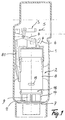
- the drain device 2 is in a bottom opening 7 of the Cistern 1 is used tightly and is at least a holding arm 8 in the upper area on the cistern wall held.
- the illustrated Drain device 2 actuators namely the actuating device 3.1 for the implementation a full flush and on the other hand the actuating device 3.2 to carry out a partial rinse
- the an angle lever 4.1 and 4.2 is assigned via depending on the desired actuation on the drain valve can be influenced.
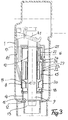
- this essentially consists from a float chamber 8, which is concentric with the as Drain valve 9 trained overflow pipe is arranged.
- the inner wall 10 of the float chamber designed as an annular space 8 also serves as a guide for the drain valve 9.
- the drain valve 9 has on its lower end of a valve plate 11 on a valve seat 12 rests on the drain opening 13.
- the float chamber 8 is over Supports 14 arranged above the plane of the valve seat 12, so that there are passages through which when the drain valve 9 is raised, that contained in the cistern 1 Drain water freely through the flow opening 13 can.
- FIG. 3 shows, there is a main float in the float chamber 8 15 is arranged, which via a set screw 16 fixed but adjustable in height with the drain valve 9 a retaining ring 17 is connected.
- the float chamber 8 has at least one through opening at the lower end 18 with a small cross-section through which when filling the cistern also the float chamber 8 filled with water becomes.
- the flow cross section of the flow openings 18 is dimensioned so that when opening the Drain valve the float chamber emptied with delay is, so that this ensures that the main swimmer 15 only then drop into the closed position can when the cistern is completely empty.
- the Float chamber 8 At a distance above the passage openings 18 is the Float chamber 8 with at least one valve opening 19 provided an additional connection between the interior of the float chamber 8 and the immediate Space of the cistern 1 is available.
- An auxiliary float 20 is further provided, which is ring-shaped and at the same time as a blocking body serves for the valve opening 19.
- the auxiliary swimmer 20 is provided with an upwardly projecting holding part 21, that extends to below the retaining collar 17, over the the main float 15 with the upper end of the drain valve 9 is connected.
- a latch opening 22 provided in the one nose 23 as a swivel hook 24 trained latchable part of a driver element 25 can intervene.
- the wall of the Float chamber 8 has a slot 26 through which the nose 23 of the swivel hook 24 can reach through.
- the swivel hook 24 is also provided with a control cam 27 provided that when the driver element 25 is raised on the upper edge formed as a stop 28 Slit 26 comes up and the swivel hook 24 behind moved outside so that the nose 23 out of the locking opening 22nd is pulled out and so that is now on the main float 15 and the auxiliary float 20 supporting drain valve 9 corresponding to the sinking of the water level in the float chamber 8 can sink down.
- the driver element 25 is actuated as from supervision according to Fig. 2 can be seen on the with the Actuator 3.2 connected angle lever 4.2, that of a corresponding one, not visible in FIG. 3 Eyelet engages the driver element 25.
- the device 3.2 for performing a partial rinse is operated, as described above, via the driver element 25 and the swivel hook 24 the drain valve together with the main swimmer 15 and the auxiliary swimmer 20 raised. This is the valve opening 19 by the auxiliary swimmer designed as a blocking body 20 released.
- valve opening 19 in its free flow cross section is dimensioned larger than the drain opening 18, sinks the water level in the float chamber through the suction the amount of water running out of the cistern faster from, so that accordingly the drain valve 9 faster reaches the closed position and thus the drain opening 13 completes early. Since the pivot lever 24 with its Nose 23 can be pulled out of the latching opening 22 the drain valve 9 also drops when the actuator 3.2 is still pressed. This ensures that only the dimensioning the flow cross section of the valve opening 19 and the associated faster sink rate of the Water level in the float chamber 8 predetermined subset can flow out of the cistern.
- Fig. 2 can be seen in the embodiment shown here the arrangement hit that the upstanding holding part 21 tubular is formed and of a corresponding pipe or includes bell-shaped driver element 25 becomes.
- the upstanding holding part 21 tubular is formed and of a corresponding pipe or includes bell-shaped driver element 25 becomes.
- bell-shaped driver element 25 becomes.
- both the main swimmer as well as the auxiliary swimmer each formed as diving bells, for example as molded plastic parts are producible.
- the main swimmer and / or the auxiliary swimmer to produce a full body from a floatable material, for example as a molded body made of polystyrene.
- the part of the drain valve guided through the float chamber 8 9 is designed as a tube, so that at one Defect on the inlet valve ensures that even at closed drain valve the constantly increasing amounts of water can run freely.
Landscapes
- Health & Medical Sciences (AREA)
- Life Sciences & Earth Sciences (AREA)
- Engineering & Computer Science (AREA)
- Hydrology & Water Resources (AREA)
- Public Health (AREA)
- Water Supply & Treatment (AREA)
- Sanitary Device For Flush Toilet (AREA)
- Bidet-Like Cleaning Device And Other Flush Toilet Accessories (AREA)
Applications Claiming Priority (2)
| Application Number | Priority Date | Filing Date | Title |
|---|---|---|---|
| DE29702564U | 1997-02-14 | ||
| DE29702564U DE29702564U1 (de) | 1997-02-14 | 1997-02-14 | Ablaufvorrichtung an einem WC-Spülkasten mit wahlweiser Voll- oder Teilspülung |
Publications (3)
| Publication Number | Publication Date |
|---|---|
| EP0859093A2 true EP0859093A2 (fr) | 1998-08-19 |
| EP0859093A3 EP0859093A3 (fr) | 1998-12-23 |
| EP0859093B1 EP0859093B1 (fr) | 2004-03-24 |
Family
ID=8035937
Family Applications (1)
| Application Number | Title | Priority Date | Filing Date |
|---|---|---|---|
| EP98100346A Expired - Lifetime EP0859093B1 (fr) | 1997-02-14 | 1998-01-10 | Dispositif d'écoulement pour réservoir de chasse d'eau de toilette permettant sélectivement le rinçage complet ou partiel |
Country Status (3)
| Country | Link |
|---|---|
| EP (1) | EP0859093B1 (fr) |
| AT (1) | ATE262627T1 (fr) |
| DE (2) | DE29702564U1 (fr) |
Families Citing this family (1)
| Publication number | Priority date | Publication date | Assignee | Title |
|---|---|---|---|---|
| CN103968139B (zh) * | 2013-01-28 | 2016-08-03 | 厦门威迪亚科技有限公司 | 一种滑轨定位控制的排水阀 |
Family Cites Families (5)
| Publication number | Priority date | Publication date | Assignee | Title |
|---|---|---|---|---|
| FR2662194B1 (fr) * | 1990-05-17 | 1992-08-07 | Spmp Sa | Mecanisme de chasse interrompable, a ecoulement minimal assure. |
| FR2676480B1 (fr) * | 1991-05-16 | 1993-08-20 | Tolbert Timothy | Dispositif d'evacuation pour reservoir, a deversement variable. |
| DE4122394A1 (de) * | 1991-07-05 | 1993-01-07 | Heinrich Menge | Spuelvorrichtung |
| DE9311189U1 (de) * | 1992-09-21 | 1993-09-09 | Geberit Ag, Jona, St.Gallen | Ablaufventil für einen Spülkasten |
| DE19501355C2 (de) * | 1995-01-18 | 1997-07-10 | Friatec Keramik Kunststoff | Ablaufarmatur für einen Spülkasten |
-
1997
- 1997-02-14 DE DE29702564U patent/DE29702564U1/de not_active Expired - Lifetime
-
1998
- 1998-01-10 DE DE59811024T patent/DE59811024D1/de not_active Expired - Fee Related
- 1998-01-10 AT AT98100346T patent/ATE262627T1/de not_active IP Right Cessation
- 1998-01-10 EP EP98100346A patent/EP0859093B1/fr not_active Expired - Lifetime
Also Published As
| Publication number | Publication date |
|---|---|
| DE29702564U1 (de) | 1997-04-03 |
| ATE262627T1 (de) | 2004-04-15 |
| DE59811024D1 (de) | 2004-04-29 |
| EP0859093B1 (fr) | 2004-03-24 |
| EP0859093A3 (fr) | 1998-12-23 |
Similar Documents
| Publication | Publication Date | Title |
|---|---|---|
| EP0722020B1 (fr) | Dispositif de chasse dans un réservoir de chasse d'eau | |
| EP2865817B1 (fr) | Garniture d'écoulement pour une chasse d'eau | |
| EP0589836B1 (fr) | Clapet d'écoulement d'un réservoir de chasse d'eau | |
| EP1719844A1 (fr) | Clapet d'écoulement d'un réservoir de chasse d'eau | |
| DE69717222T2 (de) | Schwimmerventil | |
| DE19501355C2 (de) | Ablaufarmatur für einen Spülkasten | |
| EP2006458A1 (fr) | Clapet de sortie pour une chasse d'eau | |
| EP0726368B1 (fr) | Clapet de vidange pour citerne | |
| EP1672130B1 (fr) | Soupape d'évacuation d'un réservoir de chasse | |
| EP0859093B1 (fr) | Dispositif d'écoulement pour réservoir de chasse d'eau de toilette permettant sélectivement le rinçage complet ou partiel | |
| AT403819B (de) | Spülvorrichtung | |
| DE9215972U1 (de) | Spülkasten-Ablaufventil | |
| EP0791696A1 (fr) | Dispositif pour le stockage temporair et délivrance contrÔlable d'une certaine quantité d'eau | |
| EP0737784A1 (fr) | Soupage d'évacuation d'un réservoir de chasse d'eau | |
| DE2601282A1 (de) | Vorrichtung zum entleeren und selbsttaetigen fuellen eines wasserspeichers, insbesondere toilettenspuelkasten | |
| DE3121625C2 (de) | Spülkasten zur Abgabe unterschiedlicher Spülwassermengen in sanitäre Einrichtungen, wie WC-Becken o.dgl. | |
| EP0892117B1 (fr) | Dispositif d'écoulement pour un réservoir de chasse d'eau | |
| EP0962600A2 (fr) | Dispositif d'écoulement pour chasse d'eau | |
| EP1614816B1 (fr) | Dispositif de vidange et de trop-plein pour appareils sanitaires | |
| DE2526227A1 (de) | Wasserspuelkasten fuer toiletten | |
| EP4095324B1 (fr) | Système de rinçage | |
| DE69105268T2 (de) | Druckknopfspülmechanismus mit eintauchbarem Körper. | |
| DE900199C (de) | Verfahren zur Desinfizierung von Spuelaborten, Pissoiranlagen und aehnlichen sanitaeren Einrichtungen sowie Fluessigkeitszusetzapparat zur Ausfuehrung des Verfahrens | |
| WO1997022761A1 (fr) | Dispositif pour un reservoir de chasse d'eau | |
| DE2626053A1 (de) | Vorrichtung zur umwandlung eines spuelkastens festen volumens in einen spuelkasten mit veraenderbarem volumen |
Legal Events
| Date | Code | Title | Description |
|---|---|---|---|
| PUAI | Public reference made under article 153(3) epc to a published international application that has entered the european phase |
Free format text: ORIGINAL CODE: 0009012 |
|
| AK | Designated contracting states |
Kind code of ref document: A2 Designated state(s): AT BE DE FR NL |
|
| AX | Request for extension of the european patent |
Free format text: AL;LT;LV;MK;RO;SI |
|
| PUAL | Search report despatched |
Free format text: ORIGINAL CODE: 0009013 |
|
| AK | Designated contracting states |
Kind code of ref document: A3 Designated state(s): AT BE CH DE DK ES FI FR GB GR IE IT LI LU MC NL PT SE |
|
| AX | Request for extension of the european patent |
Free format text: AL;LT;LV;MK;RO;SI |
|
| 17P | Request for examination filed |
Effective date: 19990611 |
|
| AKX | Designation fees paid |
Free format text: AT BE DE FR NL |
|
| 17Q | First examination report despatched |
Effective date: 20011213 |
|
| GRAP | Despatch of communication of intention to grant a patent |
Free format text: ORIGINAL CODE: EPIDOSNIGR1 |
|
| GRAS | Grant fee paid |
Free format text: ORIGINAL CODE: EPIDOSNIGR3 |
|
| GRAA | (expected) grant |
Free format text: ORIGINAL CODE: 0009210 |
|
| AK | Designated contracting states |
Kind code of ref document: B1 Designated state(s): AT BE DE FR NL |
|
| PG25 | Lapsed in a contracting state [announced via postgrant information from national office to epo] |
Ref country code: NL Free format text: LAPSE BECAUSE OF FAILURE TO SUBMIT A TRANSLATION OF THE DESCRIPTION OR TO PAY THE FEE WITHIN THE PRESCRIBED TIME-LIMIT Effective date: 20040324 Ref country code: FR Free format text: LAPSE BECAUSE OF FAILURE TO SUBMIT A TRANSLATION OF THE DESCRIPTION OR TO PAY THE FEE WITHIN THE PRESCRIBED TIME-LIMIT Effective date: 20040324 |
|
| REF | Corresponds to: |
Ref document number: 59811024 Country of ref document: DE Date of ref document: 20040429 Kind code of ref document: P |
|
| NLV1 | Nl: lapsed or annulled due to failure to fulfill the requirements of art. 29p and 29m of the patents act | ||
| PGFP | Annual fee paid to national office [announced via postgrant information from national office to epo] |
Ref country code: DE Payment date: 20050121 Year of fee payment: 8 |
|
| PLBE | No opposition filed within time limit |
Free format text: ORIGINAL CODE: 0009261 |
|
| STAA | Information on the status of an ep patent application or granted ep patent |
Free format text: STATUS: NO OPPOSITION FILED WITHIN TIME LIMIT |
|
| PG25 | Lapsed in a contracting state [announced via postgrant information from national office to epo] |
Ref country code: BE Free format text: LAPSE BECAUSE OF NON-PAYMENT OF DUE FEES Effective date: 20050131 Ref country code: AT Free format text: LAPSE BECAUSE OF NON-PAYMENT OF DUE FEES Effective date: 20050131 |
|
| EN | Fr: translation not filed | ||
| 26N | No opposition filed |
Effective date: 20041228 |
|
| BERE | Be: lapsed |
Owner name: *SCHNEIDER HELMHOLD Effective date: 20050131 |
|
| PG25 | Lapsed in a contracting state [announced via postgrant information from national office to epo] |
Ref country code: DE Free format text: LAPSE BECAUSE OF NON-PAYMENT OF DUE FEES Effective date: 20060801 |
|
| BERE | Be: lapsed |
Owner name: *SCHNEIDER HELMHOLD Effective date: 20050131 |