EP0859196A1 - Joint élastomère en forme de cadre, particulièrement pour portes de fours - Google Patents
Joint élastomère en forme de cadre, particulièrement pour portes de fours Download PDFInfo
- Publication number
- EP0859196A1 EP0859196A1 EP97203559A EP97203559A EP0859196A1 EP 0859196 A1 EP0859196 A1 EP 0859196A1 EP 97203559 A EP97203559 A EP 97203559A EP 97203559 A EP97203559 A EP 97203559A EP 0859196 A1 EP0859196 A1 EP 0859196A1
- Authority
- EP
- European Patent Office
- Prior art keywords
- joint
- cuts
- tube
- shaped profile
- profile
- Prior art date
- Legal status (The legal status is an assumption and is not a legal conclusion. Google has not performed a legal analysis and makes no representation as to the accuracy of the status listed.)
- Granted
Links
- 239000013536 elastomeric material Substances 0.000 title claims description 9
- 230000008878 coupling Effects 0.000 claims abstract description 43
- 238000010168 coupling process Methods 0.000 claims abstract description 43
- 238000005859 coupling reaction Methods 0.000 claims abstract description 43
- 229920001296 polysiloxane Polymers 0.000 claims description 2
- 239000000463 material Substances 0.000 description 7
- 239000003292 glue Substances 0.000 description 6
- 238000009413 insulation Methods 0.000 description 4
- 230000006866 deterioration Effects 0.000 description 3
- 230000000295 complement effect Effects 0.000 description 2
- 230000008030 elimination Effects 0.000 description 2
- 238000003379 elimination reaction Methods 0.000 description 2
- 238000007789 sealing Methods 0.000 description 2
- 239000007787 solid Substances 0.000 description 2
- 238000009825 accumulation Methods 0.000 description 1
- 238000004026 adhesive bonding Methods 0.000 description 1
- 230000002542 deteriorative effect Effects 0.000 description 1
- 239000013013 elastic material Substances 0.000 description 1
- 239000007789 gas Substances 0.000 description 1
- 238000003780 insertion Methods 0.000 description 1
- 230000037431 insertion Effects 0.000 description 1
- 238000009434 installation Methods 0.000 description 1
- 238000000034 method Methods 0.000 description 1
- 230000002028 premature Effects 0.000 description 1
- 230000000717 retained effect Effects 0.000 description 1
- 230000035807 sensation Effects 0.000 description 1
- 238000005493 welding type Methods 0.000 description 1
Images


Classifications
-
- F—MECHANICAL ENGINEERING; LIGHTING; HEATING; WEAPONS; BLASTING
- F24—HEATING; RANGES; VENTILATING
- F24C—DOMESTIC STOVES OR RANGES ; DETAILS OF DOMESTIC STOVES OR RANGES, OF GENERAL APPLICATION
- F24C15/00—Details
- F24C15/02—Doors specially adapted for stoves or ranges
- F24C15/021—Doors specially adapted for stoves or ranges sealings for doors or transparent panel
Definitions
- the present invention refers to an elastomeric material frame-shaped joint, especially for oven doors.
- the purpose of the joint is to seek insulation of the inside chamber of the oven with regard to the outside when said oven door is, naturally, closed. In this way, mainly leakage of the heat produced inside the inside chamber will be prevented.
- the joint of the invention will preferably be fixed to the frame corresponding to the mouth of the oven where the respective door is coupled by means of some hinges or the like. Therefore, the joint will be fixed to the frame by means of some coupling means.
- the object of the invention is essentially centered on the connecting structure between the coupling elements and the joint itself, the joint and the coupling elements finally forming a single-piece body.
- the joint of the invention can also be installed in the mouth of different containers that include a cover to close them and to insulate them from the outside.
- joints made out of an elastomeric material frame based on a tube-shaped profile that defines a longitudinal cavity and a flange that emerges from one of its surfaces, are known.
- This type of joints is applied to the door or to the surface against which the door abuts, in such a way that the door forms a frame all along the periphery of the door or, at least, along a substantial part of said periphery.
- the joint is applied along the four sides of said opening or, alternately, along only one part of said sides, for example, along the top side and the two vertical sides, which are the ones that perhaps require better leak-tightness to prevent the leakage of heat and steam from the oven.
- British patent application GB-A-2106974 describes a joint in accordance with the above mentioned characteristics, where the joint remains placed upon the abutment surface. This document proposes the use of a simple elongated cut to allow the hook parts of the coupling elements to emerge towards the outside.
- a disadvantage of the system described in GB-A-2106974 is that upon using a cut made by a simple elongated cut and without any type of particular ending, it is relatively easy for the material to tear, right in the areas of the ends of the cut, the same stretching out, which can give rise to a detachment of the coupling element from the tube-shaped profile or breakage of the profile itself, during assembly of the coupling elements on the tube-shaped element as well as once the joint is mounted upon the door or corresponding abutment surface. Deterioration of the leak-tightness that the joint must produce by the elevation of the lips resulting from the cut over the hook emerging outside may also be produced.
- EP-A-0277098 showed another conventional system, but instead of the simple elongated cuts as the ones mentioned above, some elongated grooves or notches with a specific width, that is greater than the corresponding width of the hook part that must emerge through said notches, have been provided for.
- EP-A-0277098 also considers the possibility of using oval holes. The holes as well as the notches are established by means of eliminating the material of the wall of the tube-shaped profile, thus allowing the hook parts to emerge with a certain play.
- notches or holes made by means of eliminating material may imply certain advantages with regard to the solution based on simple cuts, since a better distribution of stress in the ends of the notches is obtained. This contributes to preventing the elastic material from tearing in said ends. In this way, the above cited disadvantages with regard to GB-A-2106974 are at least partially avoided.
- the invention proposes a new elastomeric frame-shaped joint, especially for oven doors, that basically consists of a tube-shaped profile that will be fixed to a rectangular frame preferably on three of its sides, said frame corresponding to the mouth of a conventional oven.
- the fourth side of the rectangular frame normally remains free in order to allow jointed coupling of the respective door through which one will have access to the inside chamber of the oven.
- the frame of the oven could have any other shape.
- the joint basically consists of:
- the joint also includes a plurality of coupling elements for coupling by stretching in some holes established in the surface of the frame of the oven to which the tube-shaped profile is coupled.
- the coupling elements are comprised of a base or strip placed in the inside of the longitudinal cavity and by at least one elongated hook part that extends towards the outside through the corresponding cut.
- the cited cuts in general comprise a center part and two end parts where the cuts have a change of path of at least 90°.
- the change of path can also be of at least 135° or of at least 180°.
- the surface of the joint that connects directly with the frame of the oven is capable of including one or several longitudinal ribs or lips in order to achieve greater insulation and tightness.
- the joint includes at least one solid or tube-shaped flange which participates in the tightness of the door when it is closed.
- the advantageous cuts of the joint to facilitate the fixing of the intermediate coupling means have different structures all of which have the center part and the two end parts.
- the center part is straight and in other cases it is broken. It could also be defined by two inclined profiles.
- the end parts may be defined by straight or curved profiles.
- the tube-shaped profile may have two ends placed in order to be connected. If they are connected, the profile defines a closed frame.
- the elastomeric material of the profile may be silicone or a material with similar characteristics.
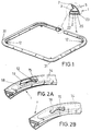
- Figure 1 is a perspective view of the elastomeric material frame-shaped joint, especially for oven doors, object of the invention. It includes some elements for coupling to the mouth of the oven.
- Figure 2a is a perspective view of one part of the joint of the invention. It mainly shows a cut through which a coupling element connected to the joint to facilitate fixing thereof to the mouth of an oven is introduced. The cut gives rise to an overlap that is collapsed upward.
- Figure 2b is a view similar to the previous one where the overlap corresponding to the cut is placed in a coplanar way with the wall of the joint where said cut has been made.
- Figure 3 is a perspective view of another joint that has a section different from the one shown in the previous figures. Aside from the cited coupling elements, there are others that are connected to the ends of the joint.
- Figure 4 is a schematic view of an oven that includes the joint of the invention.
- Figure 5 is a perspective view of a coupling element that forms an integral part of the assembly of the joint of the invention.
- Figures 6 to 17 are the representation of different cuts that are made in a wall of the tube-shaped joint of the invention in order to facilitate the attachment of the coupling elements to the joint itself.
- the elastomeric material frame-shaped joint especially for oven doors comprises a tube-shaped profile (1, 1'), that in principle has a front surface (2), a rear surface (3), a longitudinal canal or cavity (4), as well as a flange that originates from the rear surface (3) and that may be tube-shaped (5), as represented in figures 1 and 2 or simply solid made from a fin (6) (see figure 3).
- the flanges (5) and (6) finish off in a longitudinal lip (7) or (8) that participates in the tightness of a door (9) of the oven (10) when the cited door is closed.
- the joint will be essentially coupled to three of the four sides of a rectangular frame (11) corresponding to the mouth of the oven (10), leaving the fourth side free to facilitate jointed coupling of the door (9).
- the joint includes several coupling elements: some intermediate ones (12) and other end elements (13).
- the former comprise a strip or base (14) and a hook (15), both forming a single-piece body.
- the end elements (13) also comprise a strip or base (16) and a hook (17).
- the joint is normally installed on three of the four sides of the frame, it could also be installed on four sides, whereby, said joint would become a closed ring, whose ends would be connected by thermo-sealing or another type of welding, then omitting the end coupling elements (13).
- the joint may have any closed or open contour.
- Said cuts comprise an elongated center part (24) connected to two end parts (25) where the cuts have a change of path of at least 90°.
- the end parts of some cuts have an arched and semicircular shape and also a shape determined by different straight sections.
- the elongated center part is in some cases straight and in other cases it has different breaks.
- the center part has a marked break (26) that is introduced towards the inside of the corresponding overlap.
- the center part of the cuts has an arched break (27) that is also introduced towards the inside of the overlap limited by the respective cut.
- some cuts where the center part thereof comprises two inclined sections (28) that are connected by means of a center curvi-concave (29) or curvi-convex (30) section, have been represented.
- the coupling elements (12) are installed in correspondence with the angular corners of the frame (11) of the oven (10), said elements (12) forming corner sections (31) in the joint.
Landscapes
- Engineering & Computer Science (AREA)
- Chemical & Material Sciences (AREA)
- Combustion & Propulsion (AREA)
- Mechanical Engineering (AREA)
- General Engineering & Computer Science (AREA)
- Gasket Seals (AREA)
- Seal Device For Vehicle (AREA)
- Lining Or Joining Of Plastics Or The Like (AREA)
- Laminated Bodies (AREA)
Applications Claiming Priority (2)
| Application Number | Priority Date | Filing Date | Title |
|---|---|---|---|
| ES9700284 | 1997-02-12 | ||
| ES009700284A ES2142715B1 (es) | 1997-02-12 | 1997-02-12 | Junta en forma de marco de material elastomero, especialmente para puertas de hornos de cocina. |
Publications (2)
| Publication Number | Publication Date |
|---|---|
| EP0859196A1 true EP0859196A1 (fr) | 1998-08-19 |
| EP0859196B1 EP0859196B1 (fr) | 2003-02-05 |
Family
ID=8298215
Family Applications (1)
| Application Number | Title | Priority Date | Filing Date |
|---|---|---|---|
| EP97203559A Expired - Lifetime EP0859196B1 (fr) | 1997-02-12 | 1997-11-14 | Joint élastomère en forme de cadre, particulièrement pour portes de fours |
Country Status (4)
| Country | Link |
|---|---|
| EP (1) | EP0859196B1 (fr) |
| AT (1) | ATE232288T1 (fr) |
| DE (1) | DE69718891T2 (fr) |
| ES (1) | ES2142715B1 (fr) |
Cited By (2)
| Publication number | Priority date | Publication date | Assignee | Title |
|---|---|---|---|---|
| DE19935836A1 (de) * | 1999-07-29 | 2001-02-08 | Bsh Bosch Siemens Hausgeraete | Gargerät mit einem Dichtungsprofil und entsprechendes Dichtungsprofil |
| WO2007144116A1 (fr) * | 2006-06-12 | 2007-12-21 | Rehau Ag + Co | Élément rigidificateur pour des profilés d'étanchéité à cavité |
Families Citing this family (2)
| Publication number | Priority date | Publication date | Assignee | Title |
|---|---|---|---|---|
| DE102004032931A1 (de) * | 2004-07-07 | 2006-02-02 | BSH Bosch und Siemens Hausgeräte GmbH | Backofen mit einer Backofentürdichtung |
| KR101800754B1 (ko) | 2016-06-17 | 2017-11-24 | 린나이코리아 주식회사 | 오븐 캐비넷 가스켓 |
Citations (4)
| Publication number | Priority date | Publication date | Assignee | Title |
|---|---|---|---|---|
| GB2106974A (en) * | 1981-10-06 | 1983-04-20 | Silicone Altimex Ltd | Door seal |
| GB2113827A (en) * | 1982-01-23 | 1983-08-10 | Silicone Fabrications Limited | Stretch gaskets |
| EP0277098A2 (fr) * | 1987-01-21 | 1988-08-03 | GIAT S.r.L. | Joint de porte de four en élastomère ayant la forme d'un cadre fermé ou ouvert |
| EP0851177A1 (fr) | 1996-12-18 | 1998-07-01 | POSA S.p.A. | Joint d'étanchéité en élastomère, en particulier pour porte de four de cuisson |
Family Cites Families (2)
| Publication number | Priority date | Publication date | Assignee | Title |
|---|---|---|---|---|
| US3847199A (en) * | 1973-01-14 | 1974-11-12 | K & M Rubber Co | Removable oven door gasket and method of making same |
| FR2553170B1 (fr) * | 1983-10-11 | 1987-10-30 | Gerland | Joint d'etancheite en elastomere constitue d'une seule longueur de profile |
-
1997
- 1997-02-12 ES ES009700284A patent/ES2142715B1/es not_active Expired - Fee Related
- 1997-11-14 EP EP97203559A patent/EP0859196B1/fr not_active Expired - Lifetime
- 1997-11-14 DE DE69718891T patent/DE69718891T2/de not_active Expired - Fee Related
- 1997-11-14 AT AT97203559T patent/ATE232288T1/de not_active IP Right Cessation
Patent Citations (4)
| Publication number | Priority date | Publication date | Assignee | Title |
|---|---|---|---|---|
| GB2106974A (en) * | 1981-10-06 | 1983-04-20 | Silicone Altimex Ltd | Door seal |
| GB2113827A (en) * | 1982-01-23 | 1983-08-10 | Silicone Fabrications Limited | Stretch gaskets |
| EP0277098A2 (fr) * | 1987-01-21 | 1988-08-03 | GIAT S.r.L. | Joint de porte de four en élastomère ayant la forme d'un cadre fermé ou ouvert |
| EP0851177A1 (fr) | 1996-12-18 | 1998-07-01 | POSA S.p.A. | Joint d'étanchéité en élastomère, en particulier pour porte de four de cuisson |
Cited By (3)
| Publication number | Priority date | Publication date | Assignee | Title |
|---|---|---|---|---|
| DE19935836A1 (de) * | 1999-07-29 | 2001-02-08 | Bsh Bosch Siemens Hausgeraete | Gargerät mit einem Dichtungsprofil und entsprechendes Dichtungsprofil |
| DE19935836C2 (de) * | 1999-07-29 | 2001-08-09 | Bsh Bosch Siemens Hausgeraete | Gargerät mit einem Dichtungsprofil und entsprechendes Dichtungsprofil |
| WO2007144116A1 (fr) * | 2006-06-12 | 2007-12-21 | Rehau Ag + Co | Élément rigidificateur pour des profilés d'étanchéité à cavité |
Also Published As
| Publication number | Publication date |
|---|---|
| EP0859196B1 (fr) | 2003-02-05 |
| ES2142715A1 (es) | 2000-04-16 |
| ES2142715B1 (es) | 2000-11-16 |
| ATE232288T1 (de) | 2003-02-15 |
| DE69718891D1 (de) | 2003-03-13 |
| DE69718891T2 (de) | 2003-11-27 |
Similar Documents
| Publication | Publication Date | Title |
|---|---|---|
| IT8904869A1 (it) | Tetto scorrevole o scorrevole-sollevabile per autoveicoli. | |
| JP2001054213A (ja) | 配電盤キャビネット用のフレーム架構 | |
| JPH01250551A (ja) | サンドイッチ型壁パネル | |
| JP4073495B2 (ja) | 窓枠を有する窓 | |
| JPH04108031A (ja) | 車両用ウインドモールディング | |
| EP0859196A1 (fr) | Joint élastomère en forme de cadre, particulièrement pour portes de fours | |
| IT8224450A1 (it) | Guarnizione per la fessura di contorno di un tetto scorrevole per autoveicoli | |
| CA2182712A1 (fr) | Joint en elastomere, particulierement pour portes de four de cuisson | |
| KR200196472Y1 (ko) | 건축용 패널의 조립구조 | |
| EP1929911A2 (fr) | Profilé pour cabine de douche, cabine de sauna et similaire, cadre de porte comportant ce profilé et son procédé de fabrication | |
| LU83438A1 (fr) | Profile en matiere plastique,destine a la fixation d'un double vitrage en renovation | |
| JPS6164529A (ja) | グラスラン | |
| JPH0118055Y2 (fr) | ||
| JP4071411B2 (ja) | 目地用ガスケット、該ガスケットの取付方法、及び前記ガスケットを取付けた建築物 | |
| JPH1181806A (ja) | パネル取付け部材 | |
| JP2000085373A (ja) | 自動車用ドアガラスラン | |
| JPH0122835Y2 (fr) | ||
| JPS62390Y2 (fr) | ||
| JP2001149269A (ja) | 暖房便座 | |
| PT851177E (pt) | Junta de vedacao de elastomero particularmente para portas de fornos de cozinha | |
| JP3782913B2 (ja) | 笠木ユニットの枠組み構造 | |
| KR200176255Y1 (ko) | 리어도어 디비젼채널의 설치구조 | |
| JP2740905B2 (ja) | 内動片引き窓の召合せ下部水密構造 | |
| JP3763979B2 (ja) | 曲り樋継手 | |
| KR200254742Y1 (ko) | 강화유리문용 방풍구조 |
Legal Events
| Date | Code | Title | Description |
|---|---|---|---|
| PUAI | Public reference made under article 153(3) epc to a published international application that has entered the european phase |
Free format text: ORIGINAL CODE: 0009012 |
|
| AK | Designated contracting states |
Kind code of ref document: A1 Designated state(s): AT BE CH DE FR GB GR IT LI NL PT SE |
|
| AX | Request for extension of the european patent |
Free format text: AL;LT;LV;MK;RO;SI |
|
| TPAD | Observations filed by third parties |
Free format text: ORIGINAL CODE: EPIDOS TIPA |
|
| 17P | Request for examination filed |
Effective date: 19990215 |
|
| AKX | Designation fees paid |
Free format text: AT BE CH DE FR GB GR IT LI NL PT SE |
|
| RBV | Designated contracting states (corrected) |
Designated state(s): AT BE CH DE FR GB GR IT LI NL PT SE |
|
| 17Q | First examination report despatched |
Effective date: 20000714 |
|
| GRAG | Despatch of communication of intention to grant |
Free format text: ORIGINAL CODE: EPIDOS AGRA |
|
| GRAG | Despatch of communication of intention to grant |
Free format text: ORIGINAL CODE: EPIDOS AGRA |
|
| GRAH | Despatch of communication of intention to grant a patent |
Free format text: ORIGINAL CODE: EPIDOS IGRA |
|
| GRAH | Despatch of communication of intention to grant a patent |
Free format text: ORIGINAL CODE: EPIDOS IGRA |
|
| GRAA | (expected) grant |
Free format text: ORIGINAL CODE: 0009210 |
|
| AK | Designated contracting states |
Designated state(s): AT BE CH DE FR GB GR IT LI NL PT SE |
|
| PG25 | Lapsed in a contracting state [announced via postgrant information from national office to epo] |
Ref country code: NL Free format text: LAPSE BECAUSE OF FAILURE TO SUBMIT A TRANSLATION OF THE DESCRIPTION OR TO PAY THE FEE WITHIN THE PRESCRIBED TIME-LIMIT Effective date: 20030205 Ref country code: LI Free format text: LAPSE BECAUSE OF FAILURE TO SUBMIT A TRANSLATION OF THE DESCRIPTION OR TO PAY THE FEE WITHIN THE PRESCRIBED TIME-LIMIT Effective date: 20030205 Ref country code: GR Free format text: LAPSE BECAUSE OF FAILURE TO SUBMIT A TRANSLATION OF THE DESCRIPTION OR TO PAY THE FEE WITHIN THE PRESCRIBED TIME-LIMIT Effective date: 20030205 Ref country code: CH Free format text: LAPSE BECAUSE OF FAILURE TO SUBMIT A TRANSLATION OF THE DESCRIPTION OR TO PAY THE FEE WITHIN THE PRESCRIBED TIME-LIMIT Effective date: 20030205 Ref country code: BE Free format text: LAPSE BECAUSE OF FAILURE TO SUBMIT A TRANSLATION OF THE DESCRIPTION OR TO PAY THE FEE WITHIN THE PRESCRIBED TIME-LIMIT Effective date: 20030205 Ref country code: AT Free format text: LAPSE BECAUSE OF FAILURE TO SUBMIT A TRANSLATION OF THE DESCRIPTION OR TO PAY THE FEE WITHIN THE PRESCRIBED TIME-LIMIT Effective date: 20030205 |
|
| REG | Reference to a national code |
Ref country code: GB Ref legal event code: FG4D |
|
| REG | Reference to a national code |
Ref country code: CH Ref legal event code: EP |
|
| REF | Corresponds to: |
Ref document number: 69718891 Country of ref document: DE Date of ref document: 20030313 Kind code of ref document: P |
|
| PG25 | Lapsed in a contracting state [announced via postgrant information from national office to epo] |
Ref country code: SE Free format text: LAPSE BECAUSE OF FAILURE TO SUBMIT A TRANSLATION OF THE DESCRIPTION OR TO PAY THE FEE WITHIN THE PRESCRIBED TIME-LIMIT Effective date: 20030505 Ref country code: PT Free format text: LAPSE BECAUSE OF FAILURE TO SUBMIT A TRANSLATION OF THE DESCRIPTION OR TO PAY THE FEE WITHIN THE PRESCRIBED TIME-LIMIT Effective date: 20030505 |
|
| NLV1 | Nl: lapsed or annulled due to failure to fulfill the requirements of art. 29p and 29m of the patents act | ||
| REG | Reference to a national code |
Ref country code: CH Ref legal event code: PL |
|
| ET | Fr: translation filed | ||
| PLBE | No opposition filed within time limit |
Free format text: ORIGINAL CODE: 0009261 |
|
| STAA | Information on the status of an ep patent application or granted ep patent |
Free format text: STATUS: NO OPPOSITION FILED WITHIN TIME LIMIT |
|
| 26N | No opposition filed |
Effective date: 20031106 |
|
| PGFP | Annual fee paid to national office [announced via postgrant information from national office to epo] |
Ref country code: FR Payment date: 20061027 Year of fee payment: 10 |
|
| PGFP | Annual fee paid to national office [announced via postgrant information from national office to epo] |
Ref country code: GB Payment date: 20061108 Year of fee payment: 10 |
|
| PGFP | Annual fee paid to national office [announced via postgrant information from national office to epo] |
Ref country code: IT Payment date: 20061130 Year of fee payment: 10 |
|
| PGFP | Annual fee paid to national office [announced via postgrant information from national office to epo] |
Ref country code: DE Payment date: 20061229 Year of fee payment: 10 |
|
| GBPC | Gb: european patent ceased through non-payment of renewal fee |
Effective date: 20071114 |
|
| PG25 | Lapsed in a contracting state [announced via postgrant information from national office to epo] |
Ref country code: DE Free format text: LAPSE BECAUSE OF NON-PAYMENT OF DUE FEES Effective date: 20080603 |
|
| REG | Reference to a national code |
Ref country code: FR Ref legal event code: ST Effective date: 20080930 |
|
| PG25 | Lapsed in a contracting state [announced via postgrant information from national office to epo] |
Ref country code: GB Free format text: LAPSE BECAUSE OF NON-PAYMENT OF DUE FEES Effective date: 20071114 |
|
| PG25 | Lapsed in a contracting state [announced via postgrant information from national office to epo] |
Ref country code: FR Free format text: LAPSE BECAUSE OF NON-PAYMENT OF DUE FEES Effective date: 20071130 |
|
| PG25 | Lapsed in a contracting state [announced via postgrant information from national office to epo] |
Ref country code: IT Free format text: LAPSE BECAUSE OF NON-PAYMENT OF DUE FEES Effective date: 20071114 |